TeraOhm 5kV MI 2077 User Manual Version 1.5, Code No.
Distributor: Producer: METREL d.d. Ljubljanska 77 SI-1354 Horjul Tel.: +386 1 75 58 200 Fax: +386 1 75 49 226 E-mail: metrel@metre.si http://www.metrel.si Mark on your equipment certifies that this equipment meets the requirements of the EU (European Union) concerning safety and interference causing equipment regulations © 2002 Metrel No part of this publication may be reproduced or utilized in any form or by any means without permission in writing from METREL.
TeraOhm 5kV Table of contents 1. General introduction --------------------------------------------------------------------------------- 4 1.1. Features--------------------------------------------------------------------------------------------- 4 1.2. Applied Standards -------------------------------------------------------------------------------- 4 2. Instrument Description------------------------------------------------------------------------------ 5 2.1.
TeraOhm 5kV 1. General introduction 1.1. Features The TeraOhm 5kV Tester is a portable battery / mains powered test instrument intended for testing of Insulation Resistance by using high test voltages of up to 5 kV. It operates on a SIMPLE and CLEAR basis. The instrument is designed and produced with the extensive knowledge and experience acquired through many years of dealing with similar test equipment.
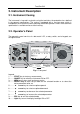
TeraOhm 5kV 2. Instrument Description 2.1. Instrument Casing The instrument is housed in a plastic casing that maintains the protection class defined in the general specifications. The casing is equipped with a carrying strap, which is intended for the instrument to be used hung around the operator’s neck. Short technical specification is available on base of the housing. 2.2. Operator’s Panel The operator’s panel consists of a dot matrix LCD, a rotary switch, and a keypad; see the figure below. 4..8 4..
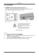
TeraOhm 5kV 2.3. Connectors The TeraOhm 5 kV Tester contains the following connections: - Connection of test leads to three banana safety sockets (1, 2, 3), - Connection of the communication cable to the 9-pin RS 232 connector (4) and - Mains supply cable connection to the mains socket (5). Fig. 2. Connectors Legend: 1.......... Positive Insulation Resistance test terminal. 2.......... Negative Insulation Resistance test terminal. 3..........
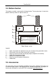
TeraOhm 5kV 2.4. Bottom Section The bottom assembly is presented in the figure below. The carrying strap is fixed to the bottom section by means of a plastic cover (2). 1 2 3 4 5 6 DISCONNECT ALL TEST LEADS AND SWITCH OFF INSTRUMENT, BEFORE REMOVING THIS BATTERY/FUSE COVER - HAZARDOUS VOLTAGE! DO NOT CHARGE IF BATTERY COMPARTMENT CONTAINS ALKALINE CELLS! POWER SUPPLY: 6×1.2V - NiCd, NiMH RECHARGEABLE (IEC LR 14) or 6×1.
TeraOhm 5kV 3.
TeraOhm 5kV • In case of a capacitive test object (long tested cable etc.), automatic discharge of the object may not be done immediately after finishing the measurement – “Please wait, discharging” message will be displayed. HANDLING WITH CAPACITIVE LOADS ♦ Note that 40 nF charged to 1 kV or 1.6 nF charged to 5 kV are hazardous live! ♦ Never touch the measured object during the testing until it is totally discharged. ♦ Maximum external voltage between any two leads is 600 V (CAT III environment).
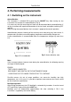
TeraOhm 5kV 4. Performing measurements 4. 1. Switching on the instrument Autocalibration The instrument is switched ON by pressing the ON/OFF key. After turning on, the instrument first executes the autocalibration (Fig. 5). It is necessary that the measuring test leads are disconnected during autocalibration. If not the instrument will require disconnection of the test leads and repeat switching OFF and ON. After finishing the autocalibration, the instrument is prepared for normal operation.
TeraOhm 5kV Off function The instrument can be switched OFF only by pressing the ON/OFF key. The auto-off function is not available due to the possible long-term measurements. 4.2. Configuration The configuration function enables the selection and adjustment of the parameters that are not directly involved in the measurement procedure (Figure 6). In the lower section of the display the supply status, date and time is shown (same in all functions).
TeraOhm 5kV 5. Measurements 5.1. Generally about DC High voltage testing The purpose of insulation tests Insulating materials are important parts of almost every electrical product. The material’s properties depend not only on its compound characteristics but also on temperature, pollution, moisture, ageing, electrical and mechanical stress, etc. Safety and operational reliability require the regular maintenance and testing of the insulation material to ensure it is kept in good operational condition.
TeraOhm 5kV Riso – the actual insulation resistance of material Ciso – capacitance of material Cpi, Rpi - represents polarization effects. The right figure shows typical currents for that circuit.
TeraOhm 5kV Time dependence test – Diagnostic test POLARISATION INDEX The purpose of this diagnostic test is to evaluate the influence of the polarization part of insulation (Rpi, Cpi). After applying a high voltage to an insulator the electric dipoles distributed in the insulator align themselves with the applied electrical field. This phenomena is called polarization. As the molecules polarize, a polarization (absorption) current that lowers the overall insulation resistance occurs.
TeraOhm 5kV Withstanding voltage test Some standards allow the use of a DC voltage as an alternative to AC withstanding voltage testing. For this purpose the test voltage has to be present across the insulation under test for a specific time. The test result passes if there is no breakdown or flash over. Standards recommend that the test starts with a low voltage and reaches the final test voltage with a slope that keeps the charging current (into Ciso) under the limit of the current threshold.
TeraOhm 5kV IL IM IM IL IA I L IA Ut 4..8 9 ESC 10 LIGHT SELECT 1 3 START MEM Ut A DIAGNOSTIC STEP TEST VOLTAGE INSULATION RESISTANCE WITHSTANDING VOLTAGE VOLTAGE CONFIG A + (Red) Guard 2 ON/OF F TeraOhm 5kV - (Black) Fig. 7. Connection of GUARD terminal to measured object (an example for measuring cable insulation is shown) where: Ut ........ Test voltage IL ......... Leakage current (resulted by surface dirt and moisture) IM ........
TeraOhm 5kV Filter option Off Fil1 Fil2 Fil3 Meaning Low pass filter with cut off frequency of 0.5 Hz in signal line. Additional low pass filter with cut off frequency of 0.05 Hz in signal line. Fil1 with increased integrating time (4 s). Fil2 with additional cyclic averaging of 5 results. Table 2. Filter options THE PURPOSE OF FILTERING In simple terms the filters smooth the measured currents by means of averaging and bandwidth reduction.
TeraOhm 5kV 5.4. Voltage measurement Selecting this function displays the following states (initial state and state with results after completion of the measurement). Initial display Display with results Fig. 8. Voltage function display states Measurement procedure: - Connect the test leads to the instrument and to the measured source. - Press the START key to start the measurement, continuous measurement starts to run. - Press the START key again to stop the measurement.
TeraOhm 5kV Measurement procedure: - Connect the test leads to the instrument and to the tested object. - Select INSULATION RESISTANCE function using the rotary switch knob. - Press the START key and release it, continuous measurement starts to run. - Wait until the test result has stabilized then press the START key again to stop the measurement or until set timer runs out (if enabled). - Wait for the object under test to be discharged.
TeraOhm 5kV Legend of displayed symbols: INSULATION RESISTANCE SETTING PARAMETERS: 1000V Unominal Timer 10min 00s Timer on/off ON Time1 01min 00s Name of selected function Set test voltage – step 50 V Duration of measurement ON: timer enabled, OFF: timer disabled Time to accept and display first Rmin and Rmax result Timer and Time1 are independent timers. Maximum time for each of them is 30 min 60 s. Warning! • Refer to Warnings chapter for safety precautions! 5.6.
TeraOhm 5kV Some applicable values: DAR value < 1.25 < 1.6 > 1.6 Tested material status Not acceptable Considered as good insulation Excellent Note: When determining Riso (15s) pay attention to the capacitance of tested object. It has to be charged-up in the first time section (15s). Approximate maximum capacitance using: [s ]. , C [μF ] = t . 10 3 U [V ] 3 max where: t........... period of first time unit (e.g. 15s) U ......... test voltage. To avoid this problem increase DIAG.
TeraOhm 5kV voltage. Timer begins to run when output test voltage reaches threshold voltage, which is product of parameters DIAG. Starting time and Unominal (nominal test voltage). Analyzing trend of measured insulation resistance and calculation of DAR and PI are very useful maintenance tests of insulating material. DIELECTRIC DISCHARGE TESTING (DD) DD is the diagnostic insulation test carried out after the completion of the Insulation Resistance measurement.
TeraOhm 5kV Notes: - A high-voltage warning symbol appears on the display during the measurement to warn the operator of a possible dangerous test voltage. - The value of capacitance is measured during the final discharge of the measured object. - If enabled, the instrument measures DD when the measured capacitance is in the range of 5 nF to 50 μF. Set-up parameters for Diagnostic Test: - Press the SELECT key, Set-up menu appears on display, see the figure 12.
TeraOhm 5kV 5.7. Step Voltage Insulation Resistance testing Selecting this function displays the following states (initial state and state with results after the completion of the measurement). Initial display Display with results Fig. 14. Step Voltage Insulation Resistance function display states Insulation is measured in five equal time periods at test voltages from one fifth up to full scale, see the figure 15.
TeraOhm 5kV Legend of displayed symbols: STEP VOLTAGE Off (Fil1, Fil2, Fil3) 1500V U=1593V I=0.00nA >1.50TΩ C=0.6nF tm:05min 15s R 300V=>300GΩ R 600V=>600GΩ R 900V=>900GΩ R1200V=>1.2TGΩ R1500V=>1.5TΩ U1= 343V U2= 655V U3= 948V U4=1284V U5=1593V Name of selected function Filter type enabled, see the chapter 5.3.
TeraOhm 5kV Note: - Maximum value for Step Time is 30 min. Warning! • Refer to Warnings chapter for safety precautions! 5.8. Withstanding voltage This function offers Withstanding Voltage test of insulation material. It covers two types of tests: a) Breakdown voltage testing of high voltage device, e.g. transient suppressors and b) DC withstanding voltage test for insulation coordination purposes. Both functions require breakdown current detection.
TeraOhm 5kV Initial display Display with results Fig. 18. Withstanding Voltage function display states Measuring procedure: - Connect the test leads to the instrument and to the measured object. - Press the START key to start the measurement. - Wait until the set timers run out or until breakdown occurs, the result is displayed. - Wait until the object under test is discharged. - The result (see the right part of the figure 18.) can optionally be saved by pressing the MEM key twice, see the chapter 6.1.
TeraOhm 5kV Set-up parameters for Withstanding Voltage: - Press the SELECT key, Set-up menu appears on display, see the figure 19. - Select parameter (line) to be set using the ↑ and ↓ keys; - Adjust set parameter using the ← and → keys. Skip to the next sub-parameter by pressing the SELECT key (if there are two or more sub-parameters) and repeat the adjustment. - Complete the set-up adjustments pressing either the Fig. 19.
TeraOhm 5kV 6. Operation with Results 6.1. Store, Recall and Clear Operation The instrument contains battery backup storage to retain the stored results. This is to enables the user first to make the measurements and later to recall them, analyze and print results or transfer them to a computer for further analysis. After pressing the MEM key menu according to the figure 20. is displayed. Save, clear and recall operations are offered. SAVE CLR RCL nnnn The nnnn means ser. number of stored result.
TeraOhm 5kV Function Voltage Insulation resistance Diagnostic test Withstanding voltage DC List of stored data Function name Measured voltage Frequency of measured voltage Ser. number of stored result Date * Time * Function name Measured insulation resistance value Set test voltage Actual test voltage - measured value Actual test current - measured value Capacitance of tested object Duration of measurement Detected maximum value of measured resistance Detected minimum value of measured resistance Ser.
TeraOhm 5kV Step voltage Function name Last measured insulation resistance Set test voltage Actual test voltage - measured value Actual test current - measured value Capacitance of tested object Complete duration of measurement First step measured resistance with its nominal voltage First step actual test voltage - measured value Second step measured resistance with its nominal voltage Second step actual test voltage - measured value Third step measured resistance with its nominal voltage Third step actua
TeraOhm 5kV 7. Maintenance 7.1. Inspection To maintain the operator’s safety and to ensure the reliability of the instrument it is advisable to inspect the instrument on a regular basis. Check that the instrument and its accessories are not damaged. If any defect is found please consult your service center, distributor or manufacturer. 7.2. Battery Replacement The instrument is designed to be powered by rechargeable battery supported with mains supply.
TeraOhm 5kV Fig. 21. Correct polarity of inserted batteries Notes! • Insert cells correctly, otherwise test instrument will not operate and battery may be discharged! • If the instrument is not to be used for a long period of time remove all batteries from battery compartment. • Take into account handling and maintenance as defined by the manufacturer of battery cells in use. 7.3.
TeraOhm 5kV 8. Specifications 8.1. Measurements Insulation resistance Nominal test voltage: Current capability of test generator: Short-circuit test current: Automatic discharge of tested object: Any within 250 and 5000 V >1 mA 1.4 mA max. yes Measuring range Riso: 0.12 MΩ up to 5 TΩ*) Display range Riso Resolution Accuracy 0 ÷ 999 kΩ 1 kΩ 1.00 ÷ 9.99 MΩ 10 kΩ 10.0 ÷ 99.9 MΩ 100 kΩ 100 ÷ 999 MΩ 1 MΩ ±(5 % of reading + 3 digits) 1.00 ÷ 9.99 GΩ 10 MΩ 10.0 ÷ 99.9 GΩ 100 MΩ 100 ÷ 999 GΩ 1 GΩ 1.00 ÷ 5.
TeraOhm 5kV Generator Capability vs. Resistance Output 6 voltage 5 [kV] * 4 3 * 2 1 0 0,1 1 10 100 Resistance under test (MΩ ) * Note: examples of selected output voltage Withstanding voltage Voltage DC Display range Withstanding voltage (V) 0 ÷ 5500 Resolution 1V Accuracy ±(3 % of reading + 40 V) Leakage current Display range Itrigg (mA) 0 ÷ 1.
TeraOhm 5kV Capacitance Measuring range C: 50 μF* Display range C Resolution Accuracy 0.1 nF 0 ÷ 99.9 nF ±(5 % of reading + 2 digits) 1 nF 100 ÷ 999 nF 10 nF 1 ÷ 50 μF *Full-scale value of capacitance is defined according to the following equation: CFS = 10μF * Utest[kV] Dielectric absorption ratio DAR Display range DAR 0 ÷ 99.9 Resolution 0.01 Accuracy ±(5% of reading + 2digits) Polarization index PI Display range PI 0 ÷ 99.9 Resolution 0.
TeraOhm 5kV CONNECTING SYSTEM Three safety banana sockets......................... +OUT, -OUT and GUARD. Guard resistance ........................................... 300 kΩ DISCHARGING Every time after measurement completion. Discharging resistance: ................................. 100 kΩ ± 10 % SERIAL COMMUNICATION RS232 serial communication ......................... galvanic separated Baud rates: .................................................... 2400, 4800, 9600, 19200 baud, 1 stop bit, no parity.