
Operation Manual


TeraOhm 5kV
23
Notes:
- A high-voltage warning symbol appears on the display during the measurement to
warn the operator of a possible dangerous test voltage.
- The value of capacitance is measured during the final discharge of the measured
object.
- If enabled, the instrument measures DD when the measured capacitance is in the
range of 5 nF to 50
μF.
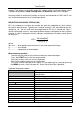
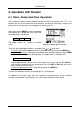
Set-up parameters for Diagnostic Test:
- Press the SELECT key, Set-up menu appears on
display, see the figure 12.
- Select parameter (line) to be set using the ↑ and ↓
keys;
- Adjust set parameter using the ← and → keys.
- Complete the set-up adjustments pressing either the
ESC key or START key (to run the measurement
directly) or changing the rotary switch position. Last
displayed settings are stored.
Fig. 12. Set-up menu in
Diagnostic Test
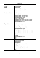
Legend of displayed symbols:
DIAGNOSTIC TEST
Name of selected function
SETTING PARAMETERS:
Unominal
1000V
Set test voltage – step 50 V
Time1 01min
Time node to take R01min result
Time2 02min
Time node to take R01min result
and calculate DAR
Time3 03min
Time node to take R03min result
and calculate PI
DD on/off ON
ON: DD enabled, OFF: DD disabled
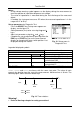
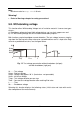
Time1, Time2 and Time3 are timers with the same start point. The value of each
presents the duration from the start of the measurement. Maximum time is 30 min. The
following figure shows the timer relationship.
0 Time1 Time2 Time3 t
Start
R15s R01min
DAR
R03min
PI
Stop
(if enabled DD)
Time1 Time2
Time2 Time3
≤
≤
Fig. 13. Timer relations
Warning!
• Refer to Warnings chapter for safety precautions!