
Operation Manual


MI 2092 Power Harmonics Analyser Section III Operation manual
30
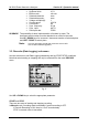
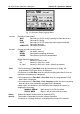
Phase angle between voltage and current.
rms phase to phase voltage (V
1-2
, V
2-3
, V
3-1
).
Total 3j signed active, apparent and reactive powers (±P
t
, ±S
t
, ±Q
t
).
Total 3j Power Factor with indication of direction (capacitive or inductive).
System frequency.
Current in neutral conductor, rms value.
fig. 16: Meter Display Screen
Note: In 3j systems with a 3wire connection, the Instrument does not display values
for the 3
rd
phase.
The central (TOTALS) line may then display two additional messages:
seq? When three phase system is not connected in the correct phase sequence (L
1
-L
2
-L
3
).
pow? When active power in one or more phase is negative.
Note: Frequency will be displayed in inverse if the instrument is unable to find a valid
sync. input. The default sync. frequency (as defined elsewhere) is used.
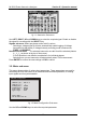
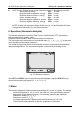
8. Scope (Oscilloscope Function)
This function provides signal waveform displays together with summary details of the
signal. The displayed signals are auto-scaled to suit the display, and may vary
dependant on the total harmonic distortion.
The top line provides information about the selected input (U
1
, I
1
, U
2
, I
2
, U
3
, I
3
), its value
and the synchronisation frequency.