
Operation Manual


MI 2092 Power Harmonics Analyser Section III Operation manual
31
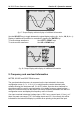
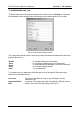
fig. 17: Scope Display without display of additional information
Use the SELECT key to toggle between the signal display options (L
1
, L
2
, L
3
, 3U, 3I, L
1
…).
Display of additional information is controlled by toggling the ENTER key.
To scale voltage waveforms: Use LEFT or RIGHT keys
To scale current waveforms: Use UP or DOWN keys
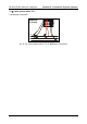
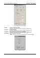
fig. 18: Scope Display with display of additional information
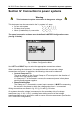
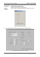
9. Frequency and overload information
METER, SCOPE and SPECTRUM screens
The synchronisation frequency is measured on the input selected in the meter
configuration menu (L
1
, L
2
, L
3
or I
1
). If no valid frequency can be detected (after
software filtering) the Instrument will, if in AUTO mode, scan the other channels for
signal that could be used for synchronisation. If no stable frequency signal can be
found, the Instrument will use the default (50-60Hz) frequency selected in the METER
configuration menu and display this frequency value in inverse.
If an input overload is detected (voltage input > 550 V ac or current input >2 V ac), or if
there is a peak over-range (770 V for voltage inputs and 2.5 V for current), this will be
indicated on the instrument display by a black arrow pointing to the particular input.