
Operation Manual


MI 2092 Power Harmonics Analyser Section IV Connection to power systems
32
Section IV Connection to power systems
Warning
This Instrument requires connection to dangerous voltages
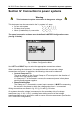
This instrument can be connected to the 3j system in 3 ways:
· 3j four wire system L
1
, L
2
, L
3
,N; I
1
, I
2
, I
3
· 3j three wires system L
12
, L
23
, L
31
; I
1
, I
2
, I
3
· Aaron (2 wattmeter) 3j connection L
12
, L
32
, I
1
, I
2
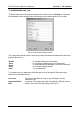
The actual connection scheme must be defined in METER Configuration menu
(see fig 19 below).
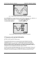
fig. 19: Meter Configuration Menu
Use LEFT and RIGHT keys to select the appropriate connections scheme.
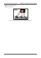
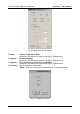
When connecting the instrument, it is essential that both current and voltage
connections are correct. In particular, the following rules must be observed:
· Current Clamp-on CTs
The arrow marked on the Current Clamp-on CTs must point in the direction of
current flow, from supply to load.
If a Clamp-on CT is connected in reverse, the measured power in that phase
would normally appear negative.
· Phase Relationships
The Clamp-on CT connected to current input connector I
1
MUST be measuring
the current in the phase to which the voltage probe from L
1
is connected.
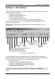
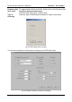
Wiring connections are shown in fig. 20, fig. 21 and fig. 22 below.
On systems where the voltage is measured on the secondary side of a voltage
transformer (say 11 kV / 110 V), a scaling factor taking account of that voltage
transformer ratio must be entered in order to ensure correct measurement (see Section
III 3.2.5 METER Configuration).