
Operation Manual


MI 2092 Power Harmonics Analyser Section VI Theory of operation
50
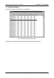
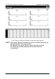
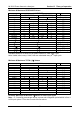
Minimum & Maximum PER PHASE Values
LOAD TYPE
VALUE CONSUMNIG GENERATING Note
inductive
capacitive inductive capacitive [formula]
m Px+ P
x
0 [3]
m Px- 0 P
x
[3]
m Qxi+ Q
x
0 0 0 [7]
m Qxc+ 0 0 0 Q
x
[7]
m Qxi- 0 0 Q
x
0 [7]
m Qxc- 0 Q
x
0 0 [7]
m PFxi+ PF
x
1 na na [8]
m PFxc+ na na 1 PF
x
[8]
m PFxi- na na PF
x
1 [8]
m PFxc- 1 PF
x
na na [8]
m U
x
U
x
[1]
m I
x
I
x
[2]
m U
x
thd U
x
thd [10] -max only
m I
x
thd I
x
thd [11] -max only
m cosj
x
cosj
x
[9]
m U
x
H
n
U
x
H
n
[12]
m I
x
H
n
I
x
H
n
[13] -max only
Available Maximum & Minimum per phase Values for each Input Cycle
Note: U
x
thd, I
x
thd, cosj
x
, U
x
H
n
, I
x
H
n
are calculated every 8
th
input cycle
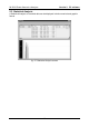
Minimum & Maximum TOTAL (3j) Values
LOAD TYPE
VALUE CONSUMNIG GENERATING Note
inductive capacitive inductive capacitive [formula]
m Pt+ P
t
0 [14]
m Pt- 0 P
t
[14]
m St+ S
t
0 [16]
m St- 0 S
t
[16]
m Qti+ Q
t
0 0 0 [15]
m Qtc+ 0 0 0 Q
t
[15]
m Qti- 0 0 Q
t
0 [15]
m Qtc- 0 Q
t
0 0 [15]
m PFti+ PF
t
1 na na [17]
m PFtc+ na na 1 PF
t
[17]
m PFti- na na PF
t
1 [17]
m PFtc- 1 PF
t
na na [17]
m I
0
I
0
m Freq Freq
Available Maximum & Minimum 3jValues for each Input Cycle
Note: P
t
, S
t
and Q
t
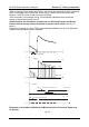
are average values in power sub integration period which is from 1
to 20 input cycles. PF
t
is also a result of those values