
Operation Manual


MI 2092 Power Harmonics Analyser Section I General information
9
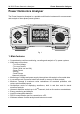
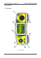
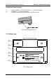
Front Panel Layout:
1.......... FUNCTION switch, selects one of seven functional/operating menus:
·
OFF
Power OFF
·
CONFIG
Instrument configuration menu
·
RECORD
Recording menu
·
ENERGY
Energy measurement
·
SPECTRUM
Harmonic analysis menu
·
METER
Basic power, current & voltage measurements
·
SCOPE
Waveforms display & control
2.......... LCD Graphic display with LED backlight, 160x116 pixels.
3.......... ESC key: To exit any procedure
4.......... ENTER key: To confirm new settings, start recording procedure
5.......... SELECT key: Enable selected signals
6.......... ARROW keys: Move cursor and select parameters
7.......... LIGHT key: LCD backlight ON/OFF
(Backlight automatically turns OFF after 30 sec. if no key action occurs)
LIGHT + - Increase display contrast
LIGHT + ¯ Decrease display contrast
8.......... HOLD key : Display screen is temporary frozen
(SCOPE ,METER and SPECTRUM functions only)
9.......... BELT slot, For attachment of a carry strap.
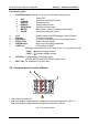
2.2. Connector panel (on side of Meter)
· Use safety test leads only!
· Max. permissable voltage between voltage input terminals and ground is 300 V
rms
Max. permissable voltage between voltage input terminals is 600 V
rms
fig. 3: Connector panel