
Operation Manual


MI 3310 / MI 3310A SigmaGT Measurements
54
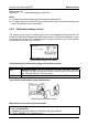
Notes:
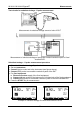
Consider any displayed warning before starting measurement!
Leakage currents into the EB/S and PE test inputs will influence substitute leakage
current measurement.
When EB/S or PE probes are connected during the test then the current through
them is also considered.
Substitute leakage current may differ substantially from that of conventional leakage
current test because of the way the test is performed. For example, the difference in
both leakage measurements will be affected by the presence of neutral to earth
noise suppression capacitors.
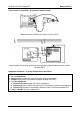
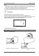
5.2.5 Substitute leakage – S probe
Leakage currents between live conductors and isolated accessible metal parts (screws,
handles etc.) are checked with this test. Capacitive leakage paths are included in the
result too. The test measures the current flowing at a test voltage of 40 V AC and the
result is scaled to the value of a nominal mains supply voltage of 230 V AC.
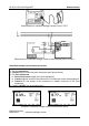
The instrument measures the insulation resistance between:
- Main test socket (L+N) and EB/S test terminals, and
- LN and EB/S test sockets.
This function is primarily intended for testing Class II DUTs and Class II parts of Class I
DUTs.
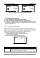
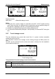
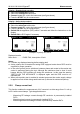
Sub leakage – S probe menu
Test parameters for substitute leakage – S probe current measurement
OUTPUT Test voltage [40 V]
LIMIT
Maximum current [0.25 mA, 0.50 mA, 0.75 mA, 1.00 mA, 1.50 mA,
2.25 mA, 2.50 mA, 3.50 mA, 4.0 mA, 4.50 mA, 5.00 mA, 5.50 mA, 6.00
mA, 7.00 mA, 8.00 mA, 9.00 mA, none]
TIME Measuring time [2 s, 3 s, 5 s, 10 s, 30 s, 60 s, 120 s, 180 s, none]