
Operation Manual

MI 3310 / MI 3310A SigmaGT Measurements
47
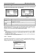
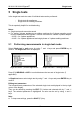
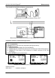
Examples of earth bond resistance measurement results
Displayed results:
Main result ............. earth bond resistance
Note:
Consider displayed warnings before starting measurement!
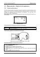
5.2.1.1 Compensation of test leads resistance (firmware release 1.24 and up)
Test leads compensation is required to eliminate the influence of test leads resistance
and instrument’s internal resistance. If a compensation value is stored this is indicated
in the message C.
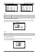
Compensation of test leads resistance procedure
Select the Earth Bond function.
Set test parameters.
Connect EB/S test probe to the instrument and short it with PE pin of test socket.
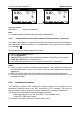
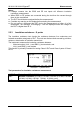
Press the CAL (F3) key for measurement.
If the calibration was performed successfully, result 0.00 is displayed.
Notes:
5.00 is the limit value for resistance compensation. If the resistance is higher than
the calibration value is reset to the default value and the compensation message
disappears.
Both 200 mA and 10 A earth bond functions are compensated at the same time.
The lead compensation is very important to obtain correct results especially if long
test leads are used.
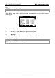
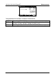
5.2.2 Insulation resistance
The insulation resistance test checks the resistance between live conductors and
accessible conductive parts of the DUT connected to PE or isolated. This test can
disclose faults caused by pollution, moisture, deterioration of insulation material etc.
The instrument measures the insulation resistance between:
- Mains test socket (L+N, +) and PE / (EB/S, -) test terminals, and
- LN and PE / (EB/S) test outputs.
This function is primarily intended for testing Class I DUTs.