
User's Guide
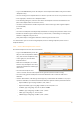
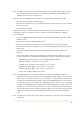
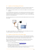
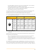
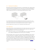
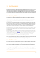
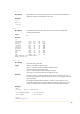
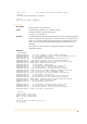
Table Of Contents
- Remote Terminal Unit M717
- Table Of Contents
- Introduction
- Installation
- Register the RTU to the M2M Gateway
- The SDI Connector
- The MPI Connector
- The Micro USB Service Connector
- About the Data Acquisition Subsystem
- SDI-12 Sensors
- Create a New Template From an Existing One
- Create a New Template From Scratch
- Interface to a Davis Vantage Pro Console
- Interface to a Thies TDL14 or DL16 Data Logger
- Mechanical Installation
- Operation
- Configuration
- Commands
- General Commands
- help
- ver
- echo
- ps
- date
- log
- attr
- pin
- hwid
- connect
- xfer
- fwupdate
- reboot
- exit
- Data Acquisition Commands
- dacq
- dacq info
- dacq sample
- dacq retrieve
- dacq abort
- dacq date
- dacq interval
- dacq direct
- dacq t
- hist
- hist info
- hist stat
- hist map
- hist purge
- Data Acquisition Legacy Commands
- sdi t
- thi t
- thi direct
- Communication Commands
- net
- net get
- net up
- net down
- net session
- modem
- modem direct
- modem pwrdown
- modem pwrup
- modem reset
- modem mode
- File System Commands
- ls
- mkdir
- cd
- cp
- pwd
- rm
- cat
- Command Line Interface Error Messages
- Attributes
- Technical Specifications

•
The attribute mpiMode determines the operation mode of the MPI interface: set to one of RS-232,
RS-422 or RS-485, depending on the configuration of the data logger.
•
The attribute mpiTermination is effective only in the RS-422 and RS-485 modes: if required, 120Ω
termination resistors can be activated on the M717 RTU side of the bus.
•
After all attributes are properly set, click the “Save” button.
To connect the 10 m M12 cable, you must open the Thies data logger and insert it through a free cable
gland. Attach the cable wires to the corresponding screw posts as shown in to the table below,
depending on the selected serial mode (RS-232, RS-422 or RS-485) and the logger type.
Note: If you are performing the operations while the Thies data-logger is powered, make sure the other end of
the cable is not connected to the M717!
Note: The wires marked in the table as “N.C.” must be left unconnected and insulated from other wires and/or
metallic parts.
After all the wires have been properly connected, you may now attach the other end of the cable to the
M717 unit. Please observe the following:
•
Before connecting the M717 cable wires to the screw posts, make sure there are no other wires
already connected! The M717 cannot be operated in parallel to another device/modem.
•
The cable shielding must be connected to the metallic housing of the logger. If the cable gland does
not provide a ground connection to the cable’s shield, a separate wire should be used to connect it
to the ground.
The configuration of the Thies Data Logger on the M2M Gateway is done similarly to the SDI-12 sensors,
but it is considerably simplified as suitable templates for standard configurations of TDL14 and DL16 are
already available. Additional tags may be defined and added according to the actual logger configuration.
M717 Pin-out
TDL14
DL16
RS-232
RS-422
RS-232
RS-422
RS-485
1
White
6 (GND)
6 (GND)
1 (GND)
1 (GND)
1 (GND)
2
Brown
5 (+12V)
5 (+12V)
7 (+12V)
7 (+12V)
7 (+12V)
3
Green
11 (TxD)
12 (TxD+)
6 (TxD)
5 (TxD+)
N.C.
4
Yellow
9 (RxD)
10 (RxD-)
2 (RxD)
3 (RxD-)
6 (B)
5
Grey
11 (TxD)
14 (TxD-)
N.C.
6 (TxD-)
N.C.
6
Pink
13 (GND)
13 (GND)
4 (GND)
4 (GND)
4 (GND)
7
Blue
N.C.
8 (RxD+)
N.C.
2 (RxD+)
5 (A)
8
Red
N.C.
N.C.
N.C.
N.C.
N.C.
Shield
Connect to metal housing
12
3
4
5
6
7
8
12