
User's Guide
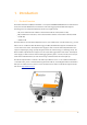
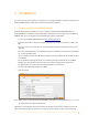
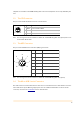
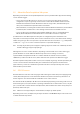
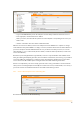
Table Of Contents
- Remote Terminal Unit M717
- Table Of Contents
- Introduction
- Installation
- Register the RTU to the M2M Gateway
- The SDI Connector
- The MPI Connector
- The Micro USB Service Connector
- About the Data Acquisition Subsystem
- SDI-12 Sensors
- Create a New Template From an Existing One
- Create a New Template From Scratch
- Interface to a Davis Vantage Pro Console
- Interface to a Thies TDL14 or DL16 Data Logger
- Mechanical Installation
- Operation
- Configuration
- Commands
- General Commands
- help
- ver
- echo
- ps
- date
- log
- attr
- pin
- hwid
- connect
- xfer
- fwupdate
- reboot
- exit
- Data Acquisition Commands
- dacq
- dacq info
- dacq sample
- dacq retrieve
- dacq abort
- dacq date
- dacq interval
- dacq direct
- dacq t
- hist
- hist info
- hist stat
- hist map
- hist purge
- Data Acquisition Legacy Commands
- sdi t
- thi t
- thi direct
- Communication Commands
- net
- net get
- net up
- net down
- net session
- modem
- modem direct
- modem pwrdown
- modem pwrup
- modem reset
- modem mode
- File System Commands
- ls
- mkdir
- cd
- cp
- pwd
- rm
- cat
- Command Line Interface Error Messages
- Attributes
- Technical Specifications

2.5. About the Data Acquisition Subsystem
Depending on the interface to the input/output devices (sensors), the M717 RTU supports the following
sensors and data loggers:
•
Sensors based on the SDI-12 protocol, version 1.3. It has various operating modes and can be
configured to accept a large variety of sensors both in native SDI-12 hardware interface and the
RS-485 balanced interface. The RS-485 interface allows for longer cables, but unfortunately not
many sensor manufacturers implement SDI-12 over RS-485.
•
Davis Instruments, Inc. Vantage Pro weather stations with the WeatherLink interface (also from Davis
Instruments). The communication is done through an RS-232 link over the MPI connector.
•
A series of data loggers manufactured by Adolf Thies GmbH & Co. KG. (e.g., models TDL14 and
TDL16). The RS-232, RS-422 and RS-485 interfaces over the MPI connector are supported.
Specific functions of the Data Acquisition subsystem are configured by means of attributes. The
subsystem is hierarchically structured, and it can have a number of sensors, each of them in turn having a
number of tags. A tag in this sense represents a specific value that can be read from — e.g., a temperature,
or written to — e.g., a coil or a valve. In other words, there are input and output tags.
Note: Currently, only the SDI-12 protocol supports output tags (by means of SDI-12 “X” commands); the Davis
and Thies data loggers support only input tags.
Although there are some common attributes, depending on the attached sensors and/or data logger,
specific attributes are used to define the functionality of the sensors and tags. For instance,
acquisitionMode and acquisitionSchedule are common attributes for all kind of sensors; however,
sdiMethod is specific to the SDI-12 sensors, while archiveInterval is specific to the Davis data logger.
The Data Acquisition Subsystem includes a First-In, First-Out (FIFO) ring storage. The data provided by the
sensors is stored in the FIFO until delivered by the communication subsystem via the Internet. The
physical memory consists of a serial flash chip, therefore the data is stored persistently and is not lost
while the RTU is powered down.
2.6. SDI-12 Sensors
The M717 RTU uses a four-wire cable carrying the SDI-12 bus signals and the bus power supply (typically
12 Volt). Alternatively the bus can be switched to RS-485 levels, but this is allowed only if all devices on
the bus support it. You cannot mix SDI-12 and RS-485 sensors on the same bus.
The switch from SDI-12 (default) to RS-485 is done automatically depending on the wiring of the sensor: if
the blue wire (pin 3) is used, then the bus is operating in RS-485 mode. For SDI-12 native sensors, only the
pins 1, 2 and 4 of the connector must be used (the brown, white and black wires of the cable), while pin 3
(blue wire) must be left open.
Note: CAN mode is not supported by the current firmware, but may be by a future update.
Depending on the sensor, a template may already be available on the M2M Gateway. To add a new sensor
to an RTU follow the steps below:
7