MX 650 Pince multimètre AC AC Clamp-on meter AC-Vielfachmesszange Pinza multimetro AC Pinza multímetrica CA MX 655 Pince multimètre ACrms/DC ACrms/DC Clamp-on meter ACrms/DC- Vielfachmesszange Pinza multimetro ACrms/DC Pinza multímetrica CArms/CC Notice de fonctionnement User's manual Bedienungsanleitung Libretto d'istruzioni Manual de instrucciones
Chapitre II User's manual Chapter II - page 16 MX 650 / MX 655 1
Chapter II TABLE OF CONTENTS 1. GENERAL INSTRUCTIONS.......................................17 1.1. 1.1.1. 1.1.2. 1.1.3. 1.1.4. 1.1.5. 1.2. 1.3. 1.4. 2. Precautions and safety measures ........................17 Before using..................................................17 When using the instrument ...........................17 Symbols ........................................................17 Instructions....................................................18 Cleaning..................................
Chapter II 1. GENERAL INSTRUCTIONS 1.1. Precautions and safety measures 1.1.1. Before using You have just acquired a 4,000-count multimeter clamp. We thank you for your confidence. This multimeter clamp complies with the IEC 61010 norms concerning electronic measuring instruments. For your own safety and to prevent damage to the instrument, you must follow the instructions given in this manual.
Chapter II 1.1.4. Instructions • Before opening the instrument, disconnect it from the measuring circuits and make sure that you are not charged with static electricity, which could irreparably damage the instrument's internal elements. • A "qualified person" is someone who is familiar with the installation, the construction, the application and the dangers at hand. This person is authorised to power up and power down the installation and equipment, in compliance with safety regulations. 1.1.5.
Chapter II 2. DESCRIPTION OF THE INSTRUMENT 2.1.
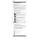
Chapter II 2.2. Description of the display 20 MX 650 MX 655 MAX Max. value MIN Min.
Chapter II 3. GENERAL DESCRIPTION 3.1. Battery installation and replacement 1. displayed when the voltage supplied by the batteries is lower than the operating voltage. 2. Before changing the batteries, position the switch to "OFF", unplug the measurement leads and disconnect the clamp from the circuit being measured . 3. Using a Phillips screwdriver, loosen the 2 screws holding the back of the case in place. 4. Replace the old battery with a new 9V battery, ensuring that the polarity is respected.
Chapter II 3.6. PEAK function (1 ms) This function enables 1 ms voltage or current PEAK signals to be captured. Before a signal is captured, the clamp must first be calibrated by holding the PEAK button down for more than 2 seconds, until "CAL" is displayed, indicating that the offset has been correctly taken into account. Choose the positive or negative sign of the peak (P+ or P-) with short presses on the PEAK button.
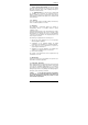
Chapter II 4.2. DC voltage measurement • (MX 650) Set the switch to V. • (MX 655) Set the switch to V. 600 Press on the / button to display the symbol (direct signal). Connect the red test lead to the "+" input terminal and the black test lead to the "COM" input terminal. Then place the touch prods in contact with the points where the DC voltage is to be measured. Then read the result on the display. 1000 PEAK 1mS HOLD A 1000 V 400 40 Hz REL 750 1000 600 6 00V 4.3.
Chapter II 4.4. Measurement of direct current (MX 655 only) Set the switch to 1000 A . Press on the / button to symbol (direct display the signal). Once the display is stabilised, press on the ∆REL button to automatically reset the DC zero. 600 1000 PEAK 1mS HOLD A 1000 V 400 40 Hz MAX MIN Then follow the same procedure as for measuring alternating current. See previous §. REL 12.
Chapter II 4.6. Continuity test with buzzer 600V CAT II I 1000A 600 V CAT I II PEAK 1000 A 1mS PEAK HOLD A 1mS HOLD V 1000 A 400 1000 V 400 40 40 Hz Hz REL REL 750 V 1000 V 600 V CAT III 600 V CAT III 750 V 1000 V 600V 600V Set the switch to . Connect the red test lead to the "+" terminal and the black to the "COM" terminal. Put the touch prods into contact with the circuit to be tested. If the resistance is less than R < 75 Ω ± 25 Ω, the buzzer will make a continuous sound.
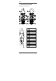
Chapter II 4.8. Measurement of the voltage frequency Set the switch to "Hz". 600 Connect the red test lead to the "+" terminal and the black test lead to the "COM" terminal. 1000 PEAK 1mS HOLD A 1000 Place the touch prods in contact with the points whose frequency is to be measured. V 400 40 Hz REL Read the result on the display. 750 1000 600 600V 4.9. Measurement of the current frequency Set the switch to "Hz". Open the clamp by pressing the trigger.
Chapter II 5. TECHNICAL SPECIFICATIONS 5.1. General Only the values assigned tolerances or the limits declared constitute guaranteed values. The values without any tolerance are given as indications. The symbol is displayed when input signal exceeds measuring limit in 40 A~ (MX 650), 40 and 400 A~ (MX 655), resistance and continuity range. In voltage, current and frequency range, this symbol will not be shown even the read reach the measuring limit of : 750 VAC, 1000 VDC, 1000 AAC/DC, 10 Hz. 5.2.
Chapter II 5.2.4. Alternating current (MX 650 automatic ranges) Range Meas. range 40 A 0.05 to 39.99 A 400 A 40.0 to 400.0 A 1000 A 400 to 1000 A Frequency Resol. 50…500 Hz 0.01 A 500…1000 Hz 50…500 Hz 0.1 A 500…1000 Hz 50…500 Hz 1A 500…1000 Hz Accuracy 1.9% L + 5 ct 3% L + 5 ct 1.9% L + 5 ct 3% L + 5 ct 1.9% L + 5 ct 3% L + 5 ct Protection against overloads: 1000 ARMS (in 40 A range) and 1500 Arms (in 400 A and 1000 A ranges) (MX 655) Range Meas. range 40 A 0.05 to 39.99 A 400 A* 40.
Chapter II 5.4. General information Digital display 3 ¾ digit LCD with max. reading of 3,999 counts Analogue display 42-segment bargraph Polarity When a negative signal is applied, the signal appears. Low battery indicator is displayed when the voltage supplied by the batteries is lower than the operating voltage. Measurements are no longer guaranteed.
METRIX Parc des Glaisins 6, avenue du pré de Challes B. P. 330 F - 74943 ANNECY-LE-VIEUX Tel. +33 04.50.64.22.22 - FAX +33 04.50.64.22.00 Copyright © X02027A00 - Ed.