
Operation Manual


Chapter II
MX 650 / MX 655
23
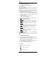
4.2. DC voltage measurement
600V
1000
750
Hz
REL
1000
PEAK
A
40
400
600
1mS
V
1000
HOLD
600
•
(MX 650) Set the switch to
V.
•
(MX 655) Set the switch to
V.
Press on the /
button to
display the
symbol (direct
signal).
Connect the red test lead to
the "+" input terminal and the
black test lead to the "COM"
input terminal.
Then place the touch prods
in contact with the points
where the DC voltage is to
be measured.
Then read the result on the
display.
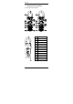
4.3. Measuring AC current
6
0
0
V
1
0
0
0
4
0
0
4
0
6
0
0
1
m
S
P
E
A
K
A
7
5
0
1
0
0
0
V
H
z
R
E
L
1
0
0
0
H
O
L
D
6
0
0
• (MX 650) Set the switch to A (corresponding to the 1000
A~ and 400 A~ automatic calibres).
• (MX 655) Set the switch to 1000 A . The symbol
(alternating signal) should be displayed. If not, press on the
/ button, to make it appear.
Open the clamp jaws by pressing the trigger. Position the
clamp around the conductor to be measured.
Release the trigger. Check the clamp is properly closed. Read
the result of the measurement on the display.
If reading is difficult, press the HOLD button and read the
result afterwards.
If necessary, for better resolution you can move to a lower
range by means of the selector switch.
Note: For safety reasons, disconnect the measuring leads
before measuring current. The clamp should encircle only one
conductor, otherwise the measurement result may be
incorrect. The best measurement is obtained with the
conductor centred in the middle of the jaws.