
Network Cables User Manual


6 Installation Guide
Installation Guide
Follow the simple steps outlined in this section of the guide to install and start
using your Metrobility “twister”.
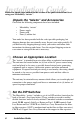
Unpack the “twister” and Accessories
Check that the following components have been included:
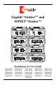
• Metrobility “twister”
• Power supply
• Power cord
• Four (4) rubber feet
Your order has been provided with the safest possible packaging, but
shipping damage does occasionally occur. Inspect your order carefully. If
you discover any shipping damage, notify your carrier and follow their
instructions for damage and claims. Save the original shipping carton in
case return or storage of the unit is necessary.
Choose an Appropriate Location
The “twister” is intended for use in either office or industrial environments.
The unit must be located within six (6) feet of the AC power source being
used and placed as far away as possible from electrical noise generating
equipment such as copiers, electrostatic printers and other motorized
equipment. If exposed twisted-pair wiring is used nearby, the wiring should
be routed as far away as possible from power cords and data cables to
minimize interference.
The unit may be oriented in any manner which allows you to make physical
connection to the power supply and leaves a minimum of six (6) inches of
space for proper ventilation.
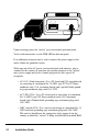
Set the DIP Switches
The Metrobility “twister” includes a set of six DIP switches located on the
back of the unit. (See figure below.) These switches are used to enable/
disable functions and are clearly marked. Unmarked switches are nonfunc-
tional. LLR1 controls Link Loss Return on Port 1. LLR2 controls Link
Loss Return on Port 2. LLCF sets Link Loss Carry Forward on the fiber-
to-fiber repeaters (LLCF is nonfunctional on the fiber-to-fiber converters).
CLCF sets Copper Loss Carry Forward on the copper-to-fiber repeaters.
2
3