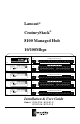
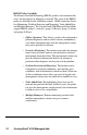
Lancast® CenturyStack® 8100 Managed Hub 10/100Mbps ® CenturyStack ® Prev ID Next 10/100 Mbps Dual Speed Ethernet Hub MDI-II MDI-II Switch Module Installed Enter 8112-01-M 1x 2x 3x 4x 13x 14x 15x 16x 5x 6x 7x 8x 9x 10x 11x 12x 22x 23x 24x 10/100 Mbps Dual Speed Ethernet Hub ® CenturyStack ® Power 100M 10M Collision Forward Link/RX 13 14 15 16 17 18 19 20 21 22 23 24 1 2 3 4 5 6 7 8 9 10 11 12 Ext. Switch ID 17x 18x 19x 20x 21x MDI-II Int.
© 1998-1999 METRObility Optical Systems, Inc. All rights reserved. Printed in USA. This publication is protected by the copyright laws of the United States and other countries, with all rights reserved.
Table of Contents CenturyStack® 8100 Managed Hub Installation & User Guide Introduction ............................................................................................... 7 Unpacking the CenturyStack 8100 Managed Hub ..................... 7 Overview of the CenturyStack 8100 Managed Hub .................. 7 Key Features ............................................................................... 9 Front Panel Overview ...............................................................
Using Expansion Modules ...................................................................... 23 Expansion Module Overview ................................................... 23 Internal Bridge Function ...................................................... 23 External Bridge Function ..................................................... 23 Backpressure (flow control) ................................................. 24 Installing a Bridge Module ...................................................
Locking the Mini Console ............................................... 53 Unlocking the Mini Console ........................................... 54 Network Configuration ........................................................ 55 IP Address Configuration ................................................ 55 Subnet Mask .................................................................... 57 Default Gateway .............................................................. 57 Out-of-Band Configuration ...........
2/3 Port Bridge Module Control/Status ................................ 87 Redundant Link Control ....................................................... 90 Security Intrusion ................................................................. 94 Monitoring the Network ........................................................... 96 Repeater Statistics Information ............................................ 97 Repeater Group Statistics Information .................................
Introduction Unpacking the CenturyStack 8100 Managed Hub Check that the following components have been included: • 8100 Series Hub • Rack Mount Bracket and Hardware • Rubber Feet • Cascade Cable • Power Cord • Installation & User Guide (this manual) Your order has been provided with the safetest possible packaging. Inspect it carefully. If your discover any shipping damage, notify the carrier and follow their instructions for damage and claims.
The 8112-01-S managed slave model shown below, includes an LED panel, 12 dual-speed auto sensing ports, 2 MDI-II ports, and a switch module expansion slot. The 8112-01-S can be fully managed by any master model. ® CenturyStack ® Power 100M 10M Collision Forward Link/RX 1 2 3 4 5 6 7 8 8 10 11 12 10/100 Mbps Dual Speed Ethernet Hub MDI-II ID MDI-II Ext. Switch Int.
Key Features The CenturyStack Dual Speed Managed Hub Series has many advanced features: 10/100Mbps Auto Sensing Ports All ports in the CenturyStack 8100 Series are dual speed auto sensing, including the MDI-II ports. Hubs automatically detect the transmission speed and set the port accordingly. Stackability Every model in the CenturyStack 8100 Series is compatible, and can be configured in the same stack with up to 6 hubs, using cascade cables.
RMON Probe Capability The Remote Network Monitoring (RMON) probe is an instrument that exists for the purpose of managing a network. The goals of the RMON probe are described in the following sections: Offline Operation, Proactive Monitoring, Problem Detection and Reporting, Value Added Data, and Multiple Managers. The CenturyStack 8100 Managed Series Hubs support RMON group (1) statistics, group (2) History, group (3) Alarm, and group (9) Event.
Redundant Link Capacity Redundant links can be configured enabling up to 24 pairs in a CenturyStack. For each pair of redundant links one port must be set as the primary and active, the other as backup and isolated. If the primary port fails, it is isolated and the backup port is set to primary and active. Address Tracking Capability CenturyStack provides MAC Address based tracking capability for traffic analysis to diagnose network problems such as Intrusion.
Front Panel Overview: Managed Slaves An LED panel, 12 dual-speed, auto sensing ports, switch module installed LED, and 2 MDI-II shared ports are on the front panel of the unit. See below. An LED panel, 24 dual-speed, auto sensing ports, switch module installed LED, and 2 MDI-II shared ports are on the front panel of the unit. See below. The Switch Module Installed LED is on if a switch module is installed in the hub.
LED Indication The hub’s LEDs indicate status information for the device, its ports for both segments (10Mbps and 100Mbps), and switch status. LED Indicators 12 Port ® CenturyStack ® Link/RX 1 2 3 4 5 6 7 8 8 10 11 12 Power 100M 10M Collision Forward ID Ext. Switch Int. Switch 8112-01-S ® CenturyStack ® Link/RX 13 14 15 16 17 18 19 20 21 22 23 24 Power 100M 10M Collision Forward 1 2 3 4 5 6 7 8 9 10 11 12 Ext. Switch ID Int.
Forwarding LED* indicator meaning Forward Status Int Ext LED Switch Switch Meaning 100M On On Off A 10Mbps transmission being received by 100Mbps segment through the internal switch 100M On Off On A 10Mbps transmission being received by 100Mbps segment through the external switch 10M On On Off A 100Mbps transmission being received by 10Mbps segment through the internal switch 10M On Off On A 100Mbps transmission being received by 10Mbps segment through the external switch 100M On On
• Internal Switch (Bridge): The Internal Switch LED is always on when the internal switch (bridge) function is active and forwarding the data. • External Switch (Bridge): The External Switch LED is on when data is being forwarded from one segment to another segment through the external switch port. • Hub ID: Each linked hub is automatically assigned a hub ID number and this number is indicated in the ID indicator.
Mini Console The Mini Console is a high definition display with console keys that enables you to easily monitor and configure the system. The Mini Console provides watch diagnostic functions, including port settings, status monitoring, traffic utilization, collision, and error rate. With the Mini Console, you can configure each device in a CenturyStack hub and all of its ports. For more information see Chapter 3: Managing Through the Mini Console.
Chapter 1 Installation Choosing a Location The CenturyStack location should be less than 100 meters from servers, workstations, or switches. The CenturyStack can be desk mounted or rack mounted. CAUTION: Category 5 UTP/STP cables are environmentally sensitive. Make sure that the cable route is not too close to electrical noise sources such as power lines or fluorescent lights. Stacking The CenturyStack Managed Series are stackable in standard 19” racks. Up to six hubs can be stacked with cascade cables.
Cascading hubs with cascade cables to make a stack is as simple as connecting the Up port of one hub to the Down port of another hub as illustrated below. NMU Stackable Up Down Switch/ Transceiver NMU Stackable Up Down Switch/ Transceiver NMU Stackable Up Down Switch/ Transceiver Cascade Ports NOTE: To connect the cascade cable, the Up port on one hub connects to the Down port of another hub. Constructing a Management Hub Stack A stack can be constructed with up to six hubs in total.
• Console Management Refer to Chapter 4: Console Management • Web-BasedManagement Refer to the CenturyStack Network Management Guide • SNMP Management Refer to the CenturyStack Network Management Guide Slave Hub Role Slave hubs supply the stack with additional ports (12/24) and an additional expansion module slot. Slave hubs can be positioned above or below the master hub. The 8112-01-S and 8124-01-S can also act as stand alone unmanaged hubs.
10Mbps connections. All ports are hot pluggable. It is recommended you label each cable to identify the device or port at each end.
Connecting Fast Ethernet Switching Hubs Connect 100Mbps devices using UTP/STP Cat 5 cables with RJ-45 connectors, maximum length 5 meters, enabling sending/receiving to other fast Ethernet switching hubs. By default, each port is set to auto sensing mode. CenturyStack can detect a connected 100BASE-TX device and transmit/receive information to/from it. The distance between switching hubs can be extended up to 2km by connecting two hubs through expansion modules using fiber cable.
CenturyStack 8100 Managed Hub
Chapter 2 Using Expansion Modules Expansion Module Overview Expansion modules provide additional functions such as internal bridging of 10Mbps and 100Mbps segments and extended distances between devices.
Backpressure (flow control) When packets are passed from 100Mbps segments to 10Mbps segments the flow is restricted due to the lesser capacity of the 10Mbps segment causing backpressure and resulting in dropped packets. With flow control or backpressure enabled, packets are made to wait until the flow is unrestricted before being sent, reducing the number of dropped packets. Installing a Bridge Module Power down CenturyStack before installing a bridge module.
2. Remove the power from the hub by disconnecting the power cable from the AC outlet. 3. Remove the installed bridge module or blank cover of the expansion module slot (not the NMU slot, only the bottom slot is available) by turning the two knobs on the front counterclockwise as shown below. NMU Stackable Up AC LINE 100-240VAC 50-60Hz, 1.5A MAX Down Switch/ Transceiver Removing the Blank Module Panel 4. Insert the new module, ensuring that the edges slide through the guides, as shown below.
10. For a hub stack with a master present, you must configure the software for the installed bridge module to enable the internal bridge function because the software default setting is disabled. The default software setting will not allow the internal bridge function to enable. The software must be configured using a master hub. 11. Start a Console or Web-Based Management session and set the software configuration for the new module.
FX Module LED Indicators The LEDs on each module indicate port activity. All LEDs are green. • Link: On, indicates a link is up. • TX: On, indicates a transmission in progress. • RX: On, indicates receiving data. • FDX: On, indicates the port is set to full duplex. Off, indicates the port is set to half duplex. • Collision:On, indicates collision occurring. 2 3 Ports Switch Module LINK Link up Transmit Receive TX RX FDX COL Full Duplex Collision FX Module LEDs NOTE: Fiber Modules support 100Mbps only.
Module 8102-01-X Module 8102-01-X is either an internal bridge for bridging the internal 10Mbps and 100Mbps segments or an external 10/100BASE-TX distance extender with MDI-X and MDI-II interfaces using an RJ-45 cable. Only one of these functions can be enabled at one time. The internal or external bridge must be enabled or disabled with on board jumpers before installation. Module flow-control (backpressure) can be enabled or disabled by setting the on board jumpers before installation.
JP18 JP16 JP15 JP14 JP13 JP12 JP11 JP9 JP8 JP7 JP6 JP5 JP4 JP3 JP2 JP10 1 2 3 JP1 INT EXT I SW SW JP16 1-2 2-3 JP1 Using Expansion Modules Jumpers: Module 8102-01-X 1 2 3 Backpressure Disable Enable 1-2 2-3 JP18 29
Module 8103-01-X Module 8103-01-X is a 3-port bridge module with a two port internal bridge for bridging 10Mbps and 100Mbps segments and an external 10/100BASE-TX distance extender with MDI-X and MDI-II interfaces using an RJ-45 cable. Both of these functions can be enabled at one time, in fact, the distance extender is always enabled. The internal or external bridge must be enabled or disabled with on board jumpers before installation.
Int Sw Enable Int Sw Disable 2-3 JP1 3 2 1 1-2 3 2 1 JP7 1-2 JP6 2-3 JP5 JP2 JP4 – JP6 Backpressure Backpressure dis JP4 JP7 JP2 Jumpers: Module 8103-01-X Using Expansion Modules JP1, 31
Module 8102-03-X Module 8102-03-X provides a two port internal bridge for bridging 10Mbps and 100Mbps segments or 100BASE-FX distance extender with SC type connectors for fiber cable. The internal bridge must be enabled with on board jumpers before installation. The external distance extender is enabled by default. Module flow-control (backpressure) can be enabled or disabled by setting the on board jumpers before installation.
JP1 HDX 1-2 FDX 2-3 JP1 JP2 INT EXT I SW SW JP17 1-2 2-3 3 2 1 JP19 JP17 JP16 JP15 JP14 JP13 JP12 JP11 JP10 JP9 JP8 JP7 JP6 JP5 JP4 JP3 3 2 1 JP2 Using Expansion Modules Jumpers: Module 8102-03-X 3 2 1 Backpressure Disable Enable 1-2 2-3 JP19 33
Module 8103-03-X Module 8103-03-X provides a two port internal bridge for bridging 10Mbps and 100Mbps segments and 100BASE-FX distance extender with SC type connectors and fiber cable. The internal bridge must be enabled or disabled with on board jumpers before installation. The external distance extender is always enabled. Module flow-control (backpressure) can be enabled or disabled by setting the on board jumpers before installation.
JP1 JP1 HDX 1-2 FDX 2-3 JP2, JP8 2-3 Backpressure 1-2 Backpressure dis JP8 JP7 JP6 JP2 1 2 3 3 2 1 JP5 JP3 Int Sw Enable Int Sw Disable & 2-3 1-2 JP5-7 JP3 Using Expansion Modules Jumpers: Module 8103-03-X 3 2 1 35
CenturyStack 8100 Managed Hub
Chapter 3 Managing Through the Mini Console Mini Console Overview The Mini Console is a high definition display panel that provides brilliant text and graphics. It displays information about the system, port status or other information depending on the menu selected. Extensive configuration settings can be viewed and configured with the Mini Console. The Mini Console is only available for the CenturyStack master units.
VFD Display The Vacuum Florescent Display (VFD) shows the following port and system information: %: The relative percentage of utilization or collision. Port Number Indicators: Indicates the number of a port, and by brightness, indicates status information. See the next table. Port Indicator Frame: partitioned.
Port Indicator Definition The port number indicators define the port status and activity by the way they are illuminated, such as ON, OFF, flashing and with a frame around the numbers. The following table summarizes the definition of the port indicators. Port Indicator Definitions Port No. (Green) Frame (Amber) Indicates Normal OFF Port is available but link is down. Bright OFF Port is available and link is up. Bright ON The Link is up and the administrator has disabled the port.
The following summarizes the Console Key functions. Prev: Cycles back through the current menu level. Next: Cycles forward through the current menu level. Enter: Selects the displayed menu item or when pressed and held changes a setting. Holding down the Enter key changes the default setting and places an “*” before the item indicating it is the current default.
PORT STATUS ALL PORTS PORT 1~PORT N PORT CONFIG SYS LOCKED ALL PORT PORT 1~PORT N UNIT CONFIG CONSOLE LOCK NETWORK CONFIG SET PASSWORD SYS RESTART SYS DEFAULT EIA232 CONFG SYSTEM INFO HW VER SW VER IP ADDRESS SUBNET MASK DEFAULT GATEWAY 10M PORTS 100M PORTS LINK UP LINK DOWN POLAR NORMAL POLAR REVERS NO AUTO PARTS AUTO PART ENABLE DISABLE Press “ENTER” to show the status applied to the port **** PSW ENABLED DISABLED AUTO-NEGO 10BASE-T 100BASE-X LOCK IP ADDRESS SUBNET MASK DEF GATEWAY CONTINUE CANC
Observing Network Traffic You can observe the network traffic in the Mini Console with the Utilization menu. Seven columns of gauge bars, which shift continuously from left to right as time elapses, represent the utilization rate of each segment. The gauge bar columns on the left are for the 10Mbps segment and the gauge bars on the right are for the 100Mbps segment.
Selecting a Group You can select a group to monitor and configure when there are managed hubs cascaded to the master hub. “Group” refers to a hub in the stack, the range is 1~6 when the maximum number of hubs exist in the stack. You can manage each hub using the Mini Console. To select a group: 1. From the main menu press until “GROUP SELECT” displays in the Message Zone. 2. Press . Several bars under the Port number indicate the current group, as shown below.
Monitoring Port Statistics You can monitor statistics of individual ports or all ports simultaneously using the Statistics Menu. The table, “Port Statistics Counters” lists the available counters that can be monitored. Port Statistic Counters Counter Type Displayed READABLE FRAMES The total number of frames received on the hub port. READABLE OCTETS The total number of octets of data received on the hub port.
AUTO PART Total number of times the port was auto-partitioned. TOTAL ERRORS Total errors received by the port including FCS errors, Align errors, Frame Too Long, Short Events, Late Events, Very Long Events and Rate Mismatch. Selecting a Port to Monitor 1. Press until Statistics displays in the Message Zone. K% 1 80 40 20 10 5 3 1 2 3 4 5 6 7 8 9 10 11 12 13 14 15 G-A G-B G-C G-D ID Master WWW SNMP O-O-B Statistics 2.
3. Press to move the “port cursor” to the desired port, the port number displays in the Message Zone, as shown below. K% 1 80 40 20 10 5 3 1 2 3 4 5 6 7 8 9 10 11 12 13 14 15 G-A G-B G-C G-D ID Master WWW SNMP O-O-B Scrolling to a Port 4. Press to confirm the selection of the port; and go to the counter type selection menu. The name of the port statistics counter “READABLE FRM” displays in the Message Zone as shown below.
Monitoring Port Detail Information You can monitor detailed port information for all ports at once or for individual ports using the Port Status menu. Monitoring All Ports Status To view all port status: 1. Press until “PORT STATUS” displays in the Message Zone. The current selected group is indicated by the group cursor under the port ID indicator, as shown below. K% 1 80 40 20 10 5 3 1 2 3 4 5 6 7 8 9 10 11 12 13 14 15 G-A G-B G-C G-D ID Master WWW SNMP O-O-B Port Status 2.
3. Press Enter to view all the ports’ status at once. The figure below illustrates 10Mbps ports 1, 2, 3, 4, 7, 10, 13, 14, 15, 16, 19 & 22. K% 1 80 40 20 10 5 3 1 2 3 4 5 6 7 8 9 10 11 12 13 14 15 G-A G-B G-C G-D ID Master WWW SNMP O-O-B 10Mbps Ports 4. Press to view the status of other ports. 100Mbps ports status displays. In the figure below, ports 5, 6, 8, 9, 11, 12, 17, 18, 20, 21, 23, & 24 are indicated as 100M ports.
POLAR REVERSE The receiver (Rx) polarity has been automatically crossed by the hub. NO AUTO PART Indicates all ports not auto partitioned. AUTO PART Indicates all Auto Partitioned ports. ENABLED Indicates all Enabled ports. DISABLED Indicates all Disabled ports. Monitoring Individual Port Status To view the status of individual ports: 1. Press until “PORT STATUS” displays in the Message Zone. 2. Press to go to the port selection menu. “ALL PORTS” displays in the Message Zone. 3.
Configuring Ports The PORT CONFIG menu enables you to configure individual ports or all ports at one time. You are prompted to enter the password when the console is locked. The ports must be configured to match the devices at the other end of the link. Settings such as speed must be identical. All ports are set to default to AUTO NEGO. When the AUTO NEGO mode is set, the highest speed supported by both ends is negotiated by the port and the device at the other end.
Ports 13 – 24 K% 1 80 40 20 10 5 3 1 2 Ports 1 – 12 3 4 5 6 7 8 9 10 11 12 13 14 15 G-A G-B G-C G-D ID Master WWW SNMP O-O-B Auto Negotiate Ports 3. Press to scroll through each configuration item. 4. Press Enter to apply the configuration displayed in the Message Zone to all the ports. Configuring a single port 1. With “PORT CONFIG” displayed in the Message Zone, press to go to the port selection menu. 2. Press to select an individual port. 3. Press .
4. Press to scroll through each configuration item. 5. Press to apply the currently displayed configuration to the port. The applied configuration is indicated by an asterisk sign displayed before the name of the configuration in the Message Zone as shown below, otherwise, the asterisk sign does not appear.
Configuring the Unit 1. Select UNIT CONFIGURATION from the Main Menu. K% 1 80 40 20 10 5 3 1 2 3 4 5 6 7 8 9 10 11 12 13 14 15 G-A G-B G-C G-D ID Master WWW SNMP O-O-B Unit Config Main Menu 2. Press to go to the UNIT CONFIGURATION menu. 3. Press to scroll through each configuration option. 4. Press to go to the next level of the configuration menu.
K% 1 80 40 20 10 5 3 1 2 3 4 5 6 7 8 9 10 11 12 13 14 15 G-A G-B G-C G-D ID Master WWW SNMP O-O-B Unlocked State 1. Select UNIT CONFIGURATION from the Main Menu. 2. Press to go to the UNIT CONFIGURATION menu. 3. Console Lock displays in the Message Zone. 4. Press to toggle to lock. 5. Press to set the configuration, a lock sign appears in the display.
3. You are prompted to enter the password. 4. Enter the password. The console is unlocked. Network Configuration The Network Configuration menu allows setting the hub’s IP Address, Subnet Mask and Default Gateway. The hub’s Network Configurations must be set to compatible settings with LAN configurations to make connections to the hub. Network Configuration Configuration Default IP ADDRESS 000.000.000.000 SUBNET MASK 000.000.000.000 DEFAULT GATEWAY 000.000.000.000 IPAddress Configuration 1.
K% 1 80 40 20 10 5 3 1 2 3 4 5 6 7 8 9 10 11 12 13 14 15 G-A G-B G-C G-D ID Master WWW SNMP O-O-B IP Address 5. Press to increase the digit (“0” ~ “9”). NOTE: Use “0” for a blank space, for example: entering “000” equals “0” or entering “022” equals “22”. 6. Press Enter to set the digit and move the cursor to the next digit. The current digit is blinking. 7. Repeat steps 1 & 2 until the entire IP address is entered. 8. Press to confirm.
Subnet Mask Select the SUBNET MASK option and follow the same procedure for setting an IP Address. Default Gateway Select the DEFAULT GATEWAY option and follow the same procedure for setting an IP Address. Out-of-Band Configuration You can set the Out-of-Band configuration with the EIA232 Config Menu, which allows setting the baud rate for the EIA232 port. Possible baud rates are 2400, 4800, 9600, or 19200. 1. Scroll to UNIT CONFIG and press Enter. 2. Scroll to EIA 232 CONFIG and press . 3.
word displays as four asterisks. The current digit blinks, indicating it can be configured. 1. Scroll to UNIT CONFIG and press . You are prompted to enter the password, **** PSW appears in the message zone and the first “*” flashes. Press to increase the digit. 2. Unlock the control panel by entering the default password 0000, one digit at a time by pressing once and once to progress to the next digit. 3. Repeat Step 2 three times. The control panel is unlocked. 4.
Restarting the Hub The hub will use your configurations to set up the system when it restarts. Restart the system with the Restart Menu using the following steps: 1. Scroll to UNIT CONFIG and press . 2. Scroll to SYS RESTART and press . 3. Press at “CONTINUE” or press to abort the action at the menu option “CANCEL”. 4. Press to confirm.
System Information Menu The System Information menu displays information about the device version, the device software version, and the network configuration settings (IP Address, Subnet Mask and Default Gateway).
Chapter 4 Master Hub Configuration and Console Management This Chapter is only for CenturyStack Master Hub configuration and management. When installing CenturyStack the first time, it is necessary to configure the hub through the Console Interface. Connecting to the Console Interface You can set up a management session by connecting a direct RS-232 cable between the management port on the CenturyStack and the communication port of your PC or terminal.
5. Press 2 or 3 times and the login panel to the management interface and login menu appears as shown below. See Menu Convention in the next section to understand the menu fields and commands of the console management interface. Menu Convention This section describes the types of fields and commands of console management menus and their usage. Menu Title CenturyStack – System Download Menu ( x ) Bootp Request File Download Request: Download Boot Server IP Address: |0.0.0.
You can move the cursor between items in menus using the Tab key or arrow keys. Console Management Menu conventions are listed below: Menu T itle: The menu title briefly describes the purpose of the menu. Check Box: Use to set a configuration item that is enclosed in parentheses “( )”. You can toggle this field to checked or not checked. Checked items are enabled and the procedure associated with this field will be performed.
Using the Console Program Ensure that the VT-100 compatible terminal parameters are set. Start the VT-100 compatible terminal and connect power to the hub. If the hub is already powered, press , one or more times to bring up the login menu. The login menu appears similar to the illustration below. Logging In When logging in for the first time, enter the User Name “LANCAST,” password and press . User Names and Passwords are not case sensitive.
Main Menu The management functions of CenturyStack are available from the Main Menu. A management function is selected by pressing or Up/Down Arrow keys to highlight the function of interest and pressing Enter. The Main Menu appears with the first item highlighted as below. Main Menu The Main Menu has six major selectable items: System Information, Management Setup, Device Control, Network Management, User Authentication, and System Utility.
User Authentication: Allows you to configure user names and passwords. System Utility: Allows you to configure software downloads, restart options, and Telnet session timeout intervals. Monitoring System Information The System Information Menu displays information about the system. You can view the system software and hardware information and configure the system configurations as shown below.
System Description: A textual description of the entity. This also includes the name and version identification of the system’s hardware type, software operating system, and networking software. System Object ID: This ID is the vendor’s authoritative identification of the network management subsystem contained in the entity. This value is allocated within the SMI enterprises’ subtree (1.3.6.1.4.1) and provides an easy and unambiguous means for determining what kind of device is being managed.
Setting up for Management The Management Setup Menu is used to configure CenturyStack for the available management functions. Management Setup Menu Network Configuration: Allows you to configure the IP Address, Subnet Mask, Default Gateway, and SLIP Address. Serial Port Configuration: port connections. Allows you to configure the serial SNMP Community Setup: access rights. Configure community names and Trap Receiver: Set up community trap addresses.
Network Configuration There are several ways or Network Interfaces that you can use to configure the hub. You must set up the hub using Local Console management to enable the other management capabilities: • Mini Console (see Chapter 3) • Local Console/Remote Telnet • Web-Based Management • SNMP Management The Network Configuration Menu allows setting up Ethernet and SLIP connections to the hub.
Interface: The current interface number; 1=Ethernet, 2=SLIP Interface T ype: The interface type — Ethernet or SLIP MAC Address: Displays the hub’s MAC Address, for example: 00-E0-95-00-00-05. IP Address: The dotted decimal address assigned to the CenturyStack. Subnet Mask: The dotted decimal subnet mask assigned to the CenturyStack. Default Gateway: The dotted decimal IP address of the default gateway assigned to CenturyStack.
Out-of-Band Serial Configuration Menu The baud rate, character size, parity, and stop bits are read only and not configurable. Baud Rate: The current serial port baud rate that can be configured from the Serial Port Configuration Menu. Character Size: 8 bits character size Parity: None Stop Bits: 1 stop bit IP Address: The dotted decimal address assigned to the SLIP interface of CenturyStack Subnet Mask: The dotted decimal mask assigned to the SLIP interface of CenturyStack.
Serial Port Configuration The Serial Port Configuration Menu is used to configure Console Mode connections to a VT-100 terminal emulator and Out-of-Band serial connections to a modem. ConsoleMode To view the Console Mode settings, select “Console” Mode in the Serial Port Configurations. Console Mode settings are read only. Use the settings as shown below. Console Operation Mode Out-of-Band Mode Out-of-Band mode enables setting up serial port configurations for making a connection to the hub using a modem.
Out-of-Band Operation Mode Baud Rate: The baud rate can be configured as one from 2400bps, 4800bps, 9600bps, 19200bps. The default is 9600. Character Size: 8 bits character size Parity: No parity. Stop Bits: 1 stop bit Select to retain the new configuration. The new configuration takes effect if Out-of-Band management is enabled. When SLIP is enabled, the EIA 232 port can be used for SLIP only. The EIA 232 port cannot be used to gain access to a management session via VT100 terminal emulation.
SNMP Community Setup The SNMP Community Setup Menu is used to set up SNMP communities. Up to six Community Names, Access Rights, and Status can be configured. You can add, delete, or edit SNMP community names, set the access rights and status. Community names are case sensitive, Private and private are considered different. You cannot enter the same name more than once; an error message appears at the bottom of the panel. Press the key to continue.
To add a community name: 1. Highlight an index number and press . An editable panel is presented, “SNMP Community Menu -2”. 2. Enter a name in the Input field. 3. Set the access right and status. 4. Highlight ADD, and press , the new name is entered and displayed. To edit a community name: 1. Enter an existing name in the Input field and press . 2. Change the access right and status. 3. Highlight Delete and press to delete an existing name. 4. Highlight Update and press .
Trap Receiver Setup Traps are messages sent across the network to an SNMP Network Manager. These messages alert the network manager for network management purposes. You can set up six trap receivers. You can configure the following: Community Name: The authorized SNMP community string of the remote network manager. (maximum 16 characters) IP Address: The IP Address of the remote network manager station to which traps should be sent. Status: A community name can be active or inactive.
To set up a trap receiver community name: 1. Select a Trap Community Name and press to open the configuration menu for the selected index as shown below. Configuring a Community Name The Community Name can be edited, the IP Address can be configured, and the Status can be set to Active or Inactive. Communities that are set to Inactive do not receive traps, until their status is reset to Active. Select Update and press to save changes.
Web-Based Management Configuration The Management Capability Setup Menu allows enabling or disabling Web-Based Management and Out-of-Band Management. Use the space bar to toggle between settings. Select Save and press to save the setting. Management Capability Setup Menu This menu lets you enable or disable Web-Based Management and Outof-Band Management. Web-Based Management: You can enable or disable Web-Based management. The new configuration takes effect after executing SAVE.
Out-of-Band Management Control You can enable or disable Out-of-Band management. • When connecting with local console, this setting takes effect immediately. • When connecting with Telnet, the system must be restarted before the setting takes effect.
Trap Filter Selecting this option presents the Trap Filter Menu as shown below. Trap Filter Menu This menu lets you enable or disable trap filters for those traps defined by RFC1215 and RFC1516. Marking a trap filter disables the trap and no traps are sent for the specified trap. The default is all traps enabled.
Controlling Devices The Device Control Menu displays the configurable device sub menus. Device Control Menu Repeater Group Control/Status : Allows you to read and configure all the hubs in a stack. Repeater Port Control/Status: Allows you to read and configure ports on any hub in a stack. 2/3-Port Bridge Module Control/Status: Allows you to set up any Bridge (Switch) Modules such as Module 8102-01-X, Module 8102-03-X, Module 8103-01-X, and Module 8103-03-X in a stack.
Repeater Group Control/Status The Repeater Group Control/Status displays status information for groups and allows enabling or disabling a group as well as naming and resetting the group. Repeater Group Control/Status Group Number: The ID number of a hub in the stack; the range is 1~6. Group Status Port Capacity: The maximum number of ports that can be contained within the group (12/24). Repeater T ype: The repeater type of the group.
Group Last Changed: The value of system uptime since any of the following conditions occurred: • hub cold or warm-started • this instance of group was created (such as, when a device or module was added to the system) • a change in the value of hub operational status • ports were added or removed as members of the group (such as, group admin. enabled or disabled) • any of the counters associated with this hub that have been reset. Group Partitioned Ports: in the group.
GroupReset All, some or none of the group’s function can be changed by selecting one of these options: NOTE: The selected option takes effect after SAVE is executed. • No Reset: None of these are reset. • Reset All: The function logic and counters of the group will be reset. This is identical to cold restart. • Reset Function Logic Only: The function logic of the group will be reset. The counters will be held static and will not be reset.
Repeater Port Control/Status The Repeater Port Control/Status displays status information for each port, of each linked repeater, and allows enabling/disabling, setting the speed, and enabling/disabling link status change notification for ports. Repeater Port Control/Status The Repeater Port Control/Status menu provides information about the hub’s port status. A hub can be selected with the PREV GROUP and NEXT GROUP commands and its ports selected with the PREV PORT and NEXT PORT commands.
Link Status: The current link status of the port. • Link Down: Link pulses are not detected on this port. • Link Up: Link pulses are being received on this port. NOTE: When the port link test function is disabled, the Port Link Status always returns Link Up for ports. Polarity Status: The current polarity link status of the port. • Rx Polarity Normal: The receive polarity of the given port is not reversed.
Link T est: Enable or disable link testing. Speed Control: The port speed. The port automatically connects to the 10Mbps or 100Mbps segment based on its port speed. • Auto Negotiate: The speed is detected and the duplex mode is forced to half duplex. • Force 10-TP: The port speed is forced to 10Mbps. • Force 100-TP: The port speed is forced to 100Mbps. Link Status Change Notify • Enable: The trap is sent. • Disable: The trap is not sent.
Group Number: The hub ID number assigned to the stack. (1 to 6) Bridge Module Status: Displays the current read only settings. Bridge Description: A description of the characteristics of this bridge module.
Bridge Module Control This control lists the configurable functions and provides option fields; use Ctrl + S to toggle between options. External Function Admin State: The default value is Disable. • Enable: Enables the external bridge function. • Disable: Disables external distance extender function of a given module. Once the distance extender function is disabled, you must enabled it to restore external distance extender operation. Internal Function Admin State: The default value is Disable.
Redundant Link Control The Redundant Link Control menu allows configuring up to 24 pairs of redundant links. A redundant pair consists of any two physically linked ports in the stack, where one is the primary link port and the other is the secondary link port. The primary link is the active link between two devices and the secondary is a backup and is set to inactive to prevent looping. In the event that the primary link fails, the secondary link becomes active.
Primary Link Port: This object identifies the port number of the primary link for a given redundant link pair. Secondary Link Group: This object identifies the hub ID of the secondary link for a given redundant link pair. Secondary Link Port: This object identifies the port number of the secondary link for a given redundant link pair. Active Link: This object indicates the current status for a given redundant link pair. • Primary: The port is currently the active primary link.
• • • Suspend: Indicates that the active ports are disabled and the redundant link function is temporarily suspended until you set its state to enable. NOTE: The suspend state does not cause the port to be switched over. Invalid: Purge the configuration of a redundant link pair from the system database. Return-to-primary: Selecting this option and pressing enter re-assigns the primary link as the active link again. A trap is sent to the trap receivers if the status of the redundant link is enable.
Configuring Redundant Link Control Editing a Link Pair You can edit a Link Pair by entering the Link Pair number (of an existing Link Pair) and reconfiguring the rest of the columns, then select Save, the Link Pair is updated to the new settings. Deleting a Link Pair You can delete a Link Pair by entering the Link Pair number (of an existing Link Pair) and setting the Status to Invalid, then select ; the Link Pair is removed.
Security Intrusion The Security Intrusion Control/Status Menu allows setting up security features. Security Intrusion Control/Status Menu The intrusion control enables you to set up secure ports that allow access by a single authorized MAC address. Group Number: The hub ID number that is assigned to the CenturyStack hub (1-6). Port Number: The port number of the hub that is specified in the Group Number (1-12/24). Intrusion Status • Enable: Enable the security intrusion control for the current port.
• Invalid: Purge the security intrusion control configuration for the current port from the system database. Intrusion Authentication Address Auto Learn • Enable: The hub learns the MAC address of the first device from which this port receives data. After learning the MAC address, the auto learn function is disabled and the recorded MAC address is the authorized MAC address. This address displays in the Intrusion Authentication MAC address field. • Disabled: Auto learn operation is disabled.
Monitoring the Network Statistic counters can be monitored for each repeater group and its ports. The Monitoring Network Menu displays the monitoring sub menus. Monitoring Network Menu Repeater Statistics Information: Contains Hub statistics such as Tx collisions, total frames and total errors and total octets for both 10Mbps segment and 100Mbps segment. Repeater Group Statistics Information: counters for each hub. Repeater Port Statistics Information: counters for a selected port.
Broadcast Storm Protection: Monitor the broadcast counters of each hub port to detect if broadcast storming exists in the network. Broadcast Storm Detected: Each hub port or optional module port which causes the broadcast storm displays. Repeater Statistics Information Selecting this option presents the Repeater Statistics Information Menu as shown below.
You can monitor the statistics in Absolute or Relative counters. The default is Absolute counters. Repeater Statistics Information Menu (Relative) Total Tx Collisions: The number of transmission collisions that have occurred in this hub. Total Frames: The number of frames received in this hub. Total Errors: Total errors received by the port including FCS errors, Align errors, Frame Too Long, Short Events, Late Events, Very Long Events and Rate Mismatches.
Repeater Group Statistics Information The Repeater Group Statistics Information Menu displays statistics counters for each group. Absolute Repeater Group Statistics Information Menu (Absolute) Statistics information counters for the current hub (Group Number). Counters are displayed in Absolute or Relative values by toggling the display mode. Absolute values represent the value collected since system start. You cannot clear absolute counters using the CLRCNT.
Relative Repeater Group Statistics Information Menu (Relative) Total Frames: The number of frames of valid frame length that have been received on the ports of this hub and not including FCS Error and Collision Event. Total Octets: The total number of octets contained in the valid frames that have been received on the ports of this hub. Tx Collisions: The total number of transmission collisions on this hub.
Repeater Port Statistics Information The Repeater Port Statistics Information Menu shows statistics in Absolute and Relative values. Absolute Repeater Port Statistics Information Menu (Absolute) The Repeater Port Statistics Information Menu displays counter information for the current port of the current hub. A hub can be selected with the PREV GROUP and NEXT GROUP commands and its ports can be selected with the PREV PORT and NEXT PORT commands.
Relative Repeater Port Statistics Information Menu (Relative) Display Mode: Relative counters represent the values collected since the relative mode was selected. Absolute values represent the value collected since system start. Group Number: The ID number of a hub in the stack. (1 to 6) Port Number: Port number of selected group. (1 to 12/24) Display Mode: Display counters in Absolute or Relative values. Readable Frames: Total readable frames received by the port.
FCS Errors: The total number of packets received by the port that had a bad Frame Check Sequence. Alignment Errors: Total Alignment Errors frames within the proper size (64 to 1518 octets) received by the port. Frame T oo Long: Total frames received by the port that were longer than 1518 octets (excluding framing bits, but including FCS octets). Short Events: Total frames received by the port that were shorter than 64 octets or activity duration was shorter than the event, ShortEventMaxTime.
transmissions. This counter is incremented by one each time that a port automatically isolates as a consequence of false carrier events. The conditions which cause a port to automatically isolate are defined by the transition from the False Carrier state to the Link Unstable state. The port automatically recovers. Symbol Errors (100Mbps only): Total symbol errors for 100Mbps transmissions.
Address Tracking Information The Address Tracking Information Menu provides per port based node tracking capability (MAC address based). This capability provides the basic traffic analysis function to diagnose network problems, such as Intrusion. The node tracking function records the source MAC of each data packet and provides the filters for data analysis. Address Tracking Menu Source Address Changes: This counter is incremented by one for each time that the Last Source Address for this port changes.
Source MAC Address (00-E0-95-00-00-00 for example) in the tracking list contains the value that is given by the Last Source Address for this port. This list can contain 15 entries. The list does not age out, the first entries are deleted to accommodate new entries when the list is full.
Address Search Information Selecting this option presents the Address Search Information Menu as shown below. Address Search Information Menu The CenturyStack provides per segment based source (MAC address) matching capability. The active address tracking capability is used to watch for a given MAC address and report on which port it was seen. This capability can also be used to collect the necessary information for mapping the topology of a network. Up to 8 MAC addresses can be searched simultaneously.
AddressSearchStatus • In Use: A management station has obtained ownership. • Not in Use: No other management station has obtained ownership. A management station first retrieves the values of the appropriate instances of the Address Search Lock and Address Search Status objects, periodically repeating the retrieval if necessary, until the value of Address Search Status is ‘Not In Use’. The management station then tries to set the Address Search Lock In Use.
Broadcast Storm Protection The Hub periodically monitors the broadcast counters of each hub port to detect a broadcast storm condition. If a hub port is detected to be causing a broadcast storm, it is automatically partitioned and a trap is sent to the network manager. The Hub continually monitors those ports that have been partitioned to check if the broadcast storm condition still exists. The partitioned hub port is auto recovered to normal operation once the broadcast storm condition is released.
Optional Module Broadcast Packet Rate Threshold: The number of broadcast packets received on a given optional module per second. The range is 0 to 14,880 packets per second. Port Broadcast Packet Rate Threshold: The number of broadcast packets received on a given port per second. The range is 0 to 14,880 packets per second.
Formula for calculating Broadcast packet rate Broadcast packet rate = Broadcast packet received Sampling Interval in Seconds Broadcast Storm Detected This menu displays a list of ports with a detected Broadcast Storm. Broadcast Storm Detected Menu Each broadcast storm is detected and the hub and port number are listed in this menu. If there have been no storms detected, this menu is empty. A maximum of 32 broadcast storms can be displayed, 16 per page.
User Authentication The User Authentication Menu is used to assign user login names, passwords and read/write privileges. The Mini Console password can be configured in the User Authentication Menu. User Authentication Menu To define each user authentication, select an index number and press . Use the ADD command to add a name. A user name and password can be deleted using the DELETE command. Select the EXIT command to return to the previous screen and view the results.
User Authentication Menu (editable) User Authentication Menu (updated) Select the index number first and press Enter. Enter a user name of up to 12 characters and a password of up to 6 characters, specify read/write privilege and then press .
System Utility The System Utility Menu lets you download microcode, restart the Hub, reset the Hub to the factory default, set the login time-outs, configure the upload settings and request an upload. System Utility Menu System Download: System downloads are used to update system software or replace existing software that has become corrupted. System Restart: The system can be restarted at any time and is required after certain configuration settings are made.
System Download The System Download Menu enables reading Boot Sever Information from a remote BOOTP Server and to download system configuration files, Web Server database information and system software from a remote TFTP Server. To download software check Bootp Request, select the appropriate download function, enter the filename with the full path, save the configuration and finally, restart the device from the System Restart Menu.
2. Perform a cold restart on the system. You should perform a code download only to update existing software or if existing code has become corrupted. Before performing a system download, make sure that you know the IP address of your TFTP server and the location of the files on the server. NOTE: Use the following naming convention: • Boot ROM Code download - 110Vxxx.BT • Web Pages Database Information Download – 110Vxxx.WEB • System Software Download - 110Vxxx.RT where, xxx is the version number.
System Restart Menu You can restart the system at any time without losing configuration settings, except in the case of a download. When you select Execute and then select , a warning message informs the user that system restart is going to be performed right now. Warm: A warm restart restarts the hub at the runtime code. For most cases, a warm restart is sufficient, except in the case of a BootP request or code download.
Factory Reset The Factory Reset Menu allows resetting CenturyStack to the original factory settings. All user configurations will be lost. A Confirm Messages displays before the hub is reset so the user can abort the factory reset. Factory Reset Menu The Factory Reset Menu lets you return all Hub settings to the original default settings. When you issue a factory reset, all of your custom settings are overwritten. To perform the factory reset, do the following steps: 1.
2. Select how the user wants the user authentication configuration processed during a factory reset: • Not Reset: Current user authentication configuration is saved. • Reset to factory default: Current user authentication configuration returns to factory defaults. 3. Select Execute and press . When Execute and Enter are selected, a warning message informs the user that system configuration data will be reset.
Configuration Upload Setting CenturyStack network management provides the capability to upload the hub configuration data to the remote server in binary format. You can upload your configuration files and save as a backup in case you need to restore your system settings. Configuration Upload Setting Menu Enter the TFTP Server IP Address and the chosen file name (for example: filename.CFG) and the path where the files will be uploaded on the server.
Configuration Upload Request/Status Configuration Upload Request This menu enables you to submit a request for a configuration file upload and view the status of a download. Select Submit to make the Upload Request. TFTP Server IP Address: The IP address of the server where the configuration files will be uploaded. Configuration File Name: and the full path. The name of the configuration file Current State: When the configuration file download is complete, Completed displays.
Upload Status: The status of the data transfer with regard to errors. • No Error: The upload was successfully stored in the specified configuration file. • No-Such-File: The path specified in the Configuration Filename field cannot be found on the TFTP Server. • Access V iolation: The file specified Configuration Filename field is Write Protected. • Disk Full: The disk specified Configuration Filename field is full. • Timeout: The TFTP upload timeouts expired at 20 seconds.
Chapter 5 Technical Information Product Specifications Standards Compliance IEEE 802.3 10BASE-T, 10BASE5 Ethernet IEEE 802.
Smart Mini Console Key Management Features (through Web and SNMP) BOOTP/TFTP Configuration, device/port management, and network statistics monitoring (Master only) Three keys on the front panel to perform for all the Mini Console functions VFD (Vacuum Fluorescent Display) panel displays text & graphic information Master/Slave management architecture Per port address tracking Per stack source address search capability Network traffic monitoring Duplicated IP detection Intrusion control per port security
Power Requirements 100 - 240 VAC, 50/60 Hz Internal universal power supply Environment Operating Temperature: 10°to 40° C Storage Temperature: -25° to 70° C Operating Humidity: 8% to 80% non-condensing Safety Regulations CUL (UL & CSA) EMI Certifications CE Mark FCC Class A VCCI Class 1 Dimensions W x D x H : 17.3" x 8.7" x 2.2" Weight 6.
Agency Compliance Product Safety and Compliance Statements This equipment complies with the following requirements: • UL • CSA • TUV • EN60950 (safety) • FCC Part 15, Class A • EN55022 Class A (emissions) • EN50082-1 (immunity) • IEC 825-1 Classification • Class 1 Laser Product This product shall be handled, stored and disposed of in accordance with all governing and applicable safety and environmental regulatory agency requirements.
Warranty and Servicing Information METRObility Optical Systems, Inc. warrants the CenturyStack 8100 Managed Hub to be in good working order for a period of THREE YEARS from the date of METRObility shipment. Should the unit fail anytime during said three-year period, METRObility will, at its option, replace or repair the product. This warranty is limited to defects in workmanship and materials and does not cover damage from accident, disaster, misuse, abuse or unauthorized modifications.
CenturyStack 8100 Managed Hub
STATISTICS GROUP 1~GROUP N PORT STATUS PORT CONFIG UNIT CONFIG ALL PORTS SYSTEM INFO HW VER SW VER IP ADDRESS SUBNET MASK DEFAULT GATEWAY PORT 1~PORT N 10M PORTS 100M PORTS LINK UP LINK DOWN POLAR NORMAL POLAR REVERS CONSOLE LOCK LOCK NETWORK CONFIG IP ADDRESS SUBNET MASK DEF GATEWAY SET PASSWORD ALL PORTS PORT 1~PORT N Appendix 129 PORT 1~PORT N READABLE FRM READABLE OCT FCS ERRORS ALIGN ERRORS FRM TOO LONG SHORT EVENTS RUNTS COLLISIONS LATE EVENTS VERY LONG EN RATE MISMATCH AUTO PART TOTAL E
Troubleshooting the Network Q: The local-console ‘login screen’ does not come up sometimes when a terminal (PC running terminal emulation) is connected to already booted master hub. Why? A: The screen must be refreshed, when CenturyStack is running and the terminal emulator is started. Pressing Ctrl + R refreshes the screen and the login menu appears. Q: Users of the 100Mbps segment cannot use Web-Based Management, however 10Mbps segment users can.
Q: Is there a loop detection and isolation feature available in CenturyStack, in case two switch modules (internal bridging enabled on the hardware) are installed in the same stack? A: No. The stack will go into a loop even before the software has booted. Therefore, the only control is on hardware (jumpers on the PC board) Q: In Web-Based Management, the Hub’s front panel is not displayed. A: For Netscape users, you need to clear the memory cache.
25 Manchester Street, Merrimack, NH 03054 USA tel: 603-880-1833 • fax: 603-594-2887 www.metrobility.