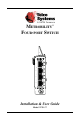
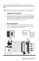
METROBILITY® FOUR-PORT SWITCH 10/100 BASE PWR 1 LK AT 2 LK AT 3 LK AT 4 LK AT Installation & User Guide Model: R104-11
Metrobility Four-port Switch R104-11 ____ 10/100Mbps Four-Port TX Switch This publication is protected by the copyright laws of the United States and other countries, with all rights reserved. No part of this publication may be reproduced, stored in a retrieval system, translated, transcribed, or transmitted, in any form, or by any means manual, electric, electronic, electromagnetic, mechanical, chemical, optical or otherwise, without prior explicit written permission of Telco Systems.
Table of Contents Metrobility 4-port Switch Installation & User Guide Overview .............................................................................................................. 4 Installation Guide ............................................................................................... 5 STEP 1: Unpack the Line Card .............................................................. 5 STEP 2: Set the Switches .......................................................................
Overview The Metrobility® R104-11 is a four-port 10/100Mbps TX switch that provides a cost-effective solution for situations in which a simple switching option with few ports is required. When configured for stacking in a Metrobility chassis, the card eliminates the need for any external equipment. This means the network administrator has one less piece of networking hardware to manage and monitor.
Installation Guide Follow the simple steps outlined in this section to install and start using the R104. NOTE: Electrostatic discharge precautions should be taken when handling any circuit board. Proper grounding is recommended (i.e., wear a wrist strap). 1 Unpack the Line Card 2 Set the Switches Your order has been provided with the safest possible packaging, but shipping damage does occasionally occur. Inspect your card carefully.
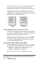
When setting DIP switches* on SW2, the OPEN position is when the lever of the switch is pushed up toward the word “OPEN.” The CLOSED position is when the lever is pushed down toward the board. OPEN -----------OPEN----------- 4 3 FD AN1 2 100M1 HDFL 100M1 1 4 1 AN1 3 FD 2 HDFL -----------OPEN----------- On the rocker DIP switch (SW1), the OPEN position is when the “OPEN” side of the switch is down and the numbered side is up.
Duplex Switch (FD) Switch FD determines the duplex mode on all ports that have autonegotiation disabled. • The ports will operate at full duplex if FD is OPEN. (default) • They will operate at half duplex if FD is CLOSED. If auto-negotiation is enabled on a port, that port will ignore the FD switch setting.
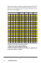
The table below displays sample port configurations and the DIP switch settings used to obtain them. The configuration column gives the autonegotiation, speed and duplex options for each port. By default, all four ports are set to auto-negotiate.
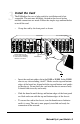
3 Install the Card The R104offers the ease of plug-and-play installation and is hotswappable. The unit must be firmly secured to the chassis before network connections are made. Follow the simple steps outlined below to install the card. • Grasp the card by the front panel as shown.
4 Connect to the Network To connect the R104 to the network, insert the twisted-pair cables into the appropriate connectors. Be sure the card is secured to the chassis by tightening the thumbscrew before making network connections. The R104 provides four shielded RJ-45 connectors that support a maximum segment length of 100 meters. Use Category 3, 4 or 5 cables for 10Mbps segments; use only Category 5 or 5E cables for 100Mbps segments. Insert your connectors as shown below.
User Guide This section contains information regarding the operating features of the Metrobility R104. LED Indicators The R104 provides several LEDs for the visible verification of unit status and proper functionality. These LEDs can assist in troubleshooting and with overall network diagnosis and management. There are separate link/speed and activity/ duplex indicators for each port. After power is applied to the card, verify correct connectivity via the LK LEDs.
Technical Specifications Network Connections Twisted-Pair Interface Connector __________________________________ Shielded RJ-45, 8-pin jack Impedance ________________________________________ 100 Ohms nominal Signal Level Output (differential) ________________ 0.95 to 1.05V (100Mbps) ___________________ 2.2 to 2.
Product Safety, EMC and Compliance Statements This equipment complies with the following requirements: • UL • CSA • CE • CB • FCC Part 15, Class A • EN55022 Class A (emissions) • EN55024: 1998 (immunity) • ICES-003 Class A (emissions) This product shall be handled, stored and disposed of in accordance with all governing and applicable safety and environmental regulatory agency requirements. The following FCC and Industry Canada compliance information is applicable to North American customers only.
Warranty and Servicing Telco Systems’ Product Warranty TELCO MAKES NO WARRANTIES EXCEPT AS HEREIN SET FORTH: Telco warrants that the equipment and accessories manufactured by Telco, when used in the application and manner for which they are intended, will be free from defects caused by faulty material or poor workmanship from the date of shipment. This warranty is subject to change at any time. The warranty that applies is that which is in effect at the time the equipment ships.
Replacement, Repair or Refund Procedure for Hardware: Telco’s sole obligation under this express warranty shall be, at Telco’s option and expense, to repair the defective product or part or deliver to Customer an equivalent product or part to replace the defective item. All products that are replaced will become the property of Telco Systems. Replacement products or parts may be new or reconditioned.
US Headquarters 2 Hampshire Street Suite 3A Foxboro MA USA 02035 tel: 1.781.551.0300 • fax: 1.781.255.2344 www.telco.