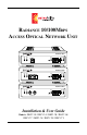
RADIANCE 10/100MBPS ACCESS OPTICAL NETWORK UNIT Radiance RA21 TM LBK ACT DIS LK ACT DIS LK x FD PWR II 100 MAN 10/100 TX 100 BASE FX Radiance RA21 TM LBK ACT DIS LK ACT DIS LK x FD PWR II 100 MAN 10/100 TX 100 BASE FX Radiance RA21 TM LBK ACT DIS LK ACT DIS LK 100 BASE FX x FD PWR II 100 MAN 10/100 TX Installation & User Guide Models: RA21-13 / RA21-14 / RA21-15 / RA21-16 / RA21-17 / RA21-1J / RA21-1X / RA21-1Y
Radiance Access Optical Network Unit 10/100Mbps Copper to Fiber: RA21-13 ____ 10/100 TX RJ-45 to FX multimode SC RA21-14 ____ 10/100 TX RJ-45 to FX singlemode SC with diagnostics RA21-15 ____ 10/100 TX RJ-45 to FX multimode ST RA21-16 ____ 10/100 TX RJ-45 to FX singlemode ST with diagnostics RA21-17 ____ 10/100 TX RJ-45 to FX singlemode SC (40km) with diagnostics RA21-1J ____ 10/100 TX RJ-45 to FX singlemode SC (100km) with diagnostics RA21-1X ____ 10/100 TX RJ-45 to FX singlemode 1550/1310nm bidirectional
Table of Contents Radiance 10/100Mbps Access Optical Network Unit Installation & User Guide Overview .............................................................................................................. 4 Installation Guide ............................................................................................... 6 STEP 1: Unpack the Unit ...................................................................... 6 STEP 2: Set the Switches ..........................................................
Overview The Metrobility Radiance 10/100Mbps Access Optical Network Unit (ONU) offers the benefits of remote management while eliminating the expenses associated an additional chassis and management card at the remote site. The compact Access ONU is a complete standalone device designed for installation at the customer premise, with no additional equipment. It supports 10Mbps and 100Mbps circuits, as well as auto-negotiation, ensuring compatibility with any customer equipment.
the sender. FEF enables the Access Line Card in the central office to detect a break in the Access ONU’s fiber port receiver. The combination of these operations, along with the unit’s remote management feature, enable easy deployment of Ethernet services to customers. The Radiance Access ONU provides the following key features: • Compatibility with any 10Mbps or 100Mbps copper Ethernet device at the customer premise.
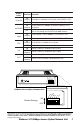
Installation Guide Follow the simple steps outlined in this section to install and start using the Radiance 10/100Mbps Access Optical Network Unit. 1 2 Unpack the Unit Your order has been provided with the safest possible packaging, but shipping damage does occasionally occur. Inspect your order carefully. If you discover any shipping damage, notify your carrier and follow instructions for damage and claims. Save the original shipping carton if return or storage of the unit is necessary.
Switch Label DUPLEX Position Function ON Full duplex is enabled on the TX port, if AUTONEG is OFF. (default) OFF AUTONEG OFF 100M FEF LLR Auto-negotiation is disabled. Duplex and speed for the TX port are set through the DUPLEX and 100M switches. ON (default) TX port speed is set to 100Mbps, if AUTONEG if OFF. OFF TX port speed is set to 10Mbps, if AUTONEG is OFF. ON Far End Fault is enabled on the FX port. (default) OFF Far End Fault is disabled on the FX port.
Duplex The DUPLEX switch sets the duplex mode on the copper port when auto-negotiation is disabled. The copper port operates at full duplex when DUPLEX is ON. It operates at half duplex when DUPLEX is OFF. When auto-negotiation is enabled, the DUPLEX switch setting is ignored. Auto-Negotiation Auto-negotiation is supported only on the copper port. When switch AUTONEG is ON, the copper port advertises 100Mbps full-duplex capabilities to its link partner.
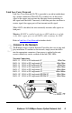
Link Loss Carry Forward Link Loss Carry Forward (LLCF) is provided as an aid in troubleshooting a remote connection. When LLCF is enabled, loss of the receive signal at the copper port prevents the fiber port from transmitting an idle signal onto the cable. Conversely, if the fiber port does not detect a receive signal, the copper port will not transmit an idle signal. When LLCF is disabled, the unit continually transmits idle signals on both ports.
TM Radiance RA21 LBK ACT TX RX ACT x FD PWR II DIS LK DIS LK 100 MAN Twisted-Pair Interface The copper port provides a shielded RJ-45 connector that supports a maximum segment length of 100 meters. Use only Category 5 cables. Fiber Optic Interface The unit’s fiber receiver (RX) is to the right of the transmitter (TX).
mentary pairs. That is, a -1X model must always be connected to a -1Y. The -1X units are designed to transmit data at a wavelength of 1550nm and receive at 1310nm. Correspondingly, the -1Y units transmit data at 1310nm and receive at 1550nm. Power is provided through the desktop power supply module. This power module is equipped with an S760 hollow-type plug for insertion into the DC jack located on the back of the unit and a standard IEC 320/C14 type AC power receptacle.
three-conductor cord, a maximum of 15 feet in length and a parallel blade, grounding-type attachment plug rated 15A, 125V. • AC 230V (USA): use a UL-listed cord set consisting of a minimum No. 18 AWG, type SVT three-conductor cord, a maximum of 15 feet in length and a Tandem blade groundingtype attachment plug rated 15A, 250V. • 240V (outside USA): use a cord set consisting of a minimum No. 18 AWG cord and grounding-type attachment plug rated 15A, 250V.
User Guide This section contains information about the operating features of the Radiance 10/100Mbps Access Optical Network Unit. LED Indicators The Radiance Access Optical Network Unit provides several LEDs on the front panel for the visible verification of unit status and proper functionality. These LEDs can help with troubleshooting and overall network diagnosis and management. There are separate Activity, Link and Disable indicators for each port.
Far End Fault ................................................................................... Enabled (ON) Link Loss Return .......................................................................... Disabled (OFF) Link Loss Carry Forward ............................................................. Disabled (OFF) Default Software Settings The following settings can only be changed via software commands.* Loopback Mode .....................................................................................
Disabling a port stops the data flow to and from that port. Although data is neither sent nor received, the disabled port continues to accept, process and transmit management packets. However, if LLCF is enabled and the opposite port has no link, management packets will not be transmitted. Remote Management Statistics Through SNMP management, NetBeacon or WebBeacon, you can view Remote Monitoring (RMON) and Ethernet statistics for the Access ONU.
Singlemode Fiber Optic Power Monitors Through software*, you can read the input and output power levels of the singlemode fiber optic port on the Access ONU. Input Power Level The accuracy of the input power monitor is ±1dBm from -28dBm to -12dBm. The accuracy is ±2dBm from -31dBm to -29dBm. The monitor is unresponsive below -31dBm. If there are no cables connected to the fiber port, the software may display a reading of -40dBm. The Access ONU peaks at -12dBm and reaches saturation at -7dBm.
Link Loss Carry Forward (LLCF)* The Access Optical Network Unit incorporates Link Loss Carry Forward as an aid in troubleshooting a remote connection. When LLCF is enabled, the ports do not transmit a link signal until they receive a link signal from the opposite port. Warning: If LLCF is enabled on the Access ONU and its copper port loses link, you will be unable to manage the ONU. Only enable LLCF when notification of a link loss is more important than remote management functionality.
Link Loss Return (LLR) The fiber optic port of the Access ONU has been designed with Link Loss Return functionality* for troubleshooting a remote connection. When LLR is enabled, the fiber port’s transmitter shuts down if its receiver fails to detect a valid receive link. LLR should only be enabled on one end of the link and is typically enabled on either the unmanaged or remote device.
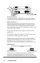
Topology Solutions CO/POP Customer Premises SNMP Control Radiance R5000 Rem ot Sta tus Rep Usee Com orti figu dB m ng and uni rati wid cati on I t h = ons nstr 0 Pa uc Con tion s th Radiance Acces Optical Network Unit Radiance 10/100Mbps Access Optical Network Unit 19
Technical Specifications Data Rate Data Rate ________ 100Mbps half duplex, 200Mbps full duplex (Fast Ethernet) ______________ 10Mbps half duplex, 20Mbps full duplex (Ethernet) Network Connections Twisted-Pair Interface Connector __________________________________ Shielded RJ-45, 8-pin jack Impedance ________________________________________ 100 Ohms nominal Signal Level Output (peak differential) ______________ 2.2 to 2.8 V (10Mbps) ___________ 0.95 to 1.
Singlemode F/O Interface — extended long haul distance support (RA21-1J) Connector _____________________________________________________ SC Wavelength _______________________________________________ 1550 nm RX Input Sensitivity ________________________________ -34 dBm minimum Output Power ______________________________________ -5 dBm to 0 dBm Supported Link Length _________________________ up to 100 km full duplex Cable Type _______________________________________ 9/125 µm SM F/O Singlemode BWDM Fiber Optic
Product Safety, EMC and Compliance Statements This equipment complies with the following requirements: • • • • • UL CSA CE EN60950 (safety) FCC Part 15, Class B • • • • • DOC Class B (emissions) EN55022 Class B (emissions) EN55024: 1998 (immunity) IEC 825-1 Classification Class 1 Laser Product This product shall be handled, stored and disposed of in accordance with all governing and applicable safety and environmental regulatory agency requirements.
Warranty and Servicing Three-Year Warranty for the Radiance Access Optical Network Unit Metrobility Optical Systems, Inc. warrants that every Radiance Access Optical Unit will be free from defects in material and workmanship for a period of THREE YEARS from the date of Metrobility shipment. This warranty covers the original user only and is not transferable.
Product Manuals The most recent version of this manual is available online at http://www.metrobility.com/support/manuals.htm To obtain additional copies of this manual, contact your reseller, or call 1.877.526.2278 or 1.603.880.1833 Product Registration To register your product, go to http://www.metrobility.com/support/registration.asp 25 Manchester Street, Merrimack, NH 03054 USA tel: 1.603.880.1833 • fax: 1.603.594.2887 www.metrobility.