RADIANCE 1000MBPS REDUNDANT INTERFACE LINE CARDS 1000 BASE 1000 BASE PWR 1000 BASE PWR PWR RESET RESET RESET M A I N LK AT M A I N LK AT M A I N LK AT P R I LK AT P R I LK AT P R I LK AT S E C LK AT S E C LK AT S E C LK AT SW SEC SW SEC SW SEC Installation & User Guide Models: R752-11 / R752-1S / R752-SS
Radiance 1000Mbps Redundant Interface Line Cards Line Card Models R752-11 _______ 1G TX RJ-45 to Dual TX RJ-45 R752-1S ______ 1G TX RJ-45 to Dual FX LC R752-SS ______ 1G FX LC to Dual FX LC Small Form-Factor Pluggable (SFP) Fiber Optic Options O211-M5 ______ SFP LC (multimode, 550 m 50 µm; 275 m 62.
Table of Contents Radiance 1000Mbps Redundant Interface Line Cards Installation & User Guide Overview ............................................................................................................. 4 Installation Guide ................................................................................................ 7 STEP 1: Unpack the Line Card ................................................................ 7 STEP 2: Set the DIP Switches ......................................................
Overview The Radiance 1000Mbps redundant interface line card offers the resiliency of data link redundancy to ensure network integrity with no down time. This link duplication provides the nonstop networking capability essential for high priority traffic and mission-critical applications. The Radiance redundant interface line card provides full redundant data paths for Gigabit Ethernet devices. The card also provides 1000Base copper-to-fiber migration.
• In addition to providing link and data on the active ports, the card can be configured to provide link or link and redundant data transmission on the inactive port. • Automatic or manually controlled switchover. • Supports full-duplex and half-duplex operation. • Link Loss Carry Forward on the R752-SS and Copper Loss Carry Forward on the R752-1S for troubleshooting remote network connections. • Compatibility with devices configured for auto-negotiation.
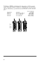
The Radiance 1000Mbps redundant interface line card is available in several models. Each model contains a MAIN port, a PRIMARY port and a SECONDARY port. Redundancy is provided between the PRIMARY and SECONDARY ports.
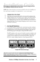
Installation Guide Follow the steps outlined in this section to install and start using your Radiance 1000Mbps redundant interface line card. NOTE: Electrostatic discharge precautions should be taken when handling any line card. Proper grounding is recommended (i.e., wear a wrist strap). 1 Unpack the Line Card 2 Set the DIP Switches Your order has been provided with the safest possible packaging, but shipping damage does occasionally occur.
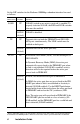
Set the DIP switches for the Radiance 1000Mbps redundant interface line card as follows: Switch Name SONR Position* UP Operation SONAR (switch on no activity received) is enabled. To properly activiate SONAR, the RED and LINK switches also must be enabled. DOWN SONAR is disabled. (default) TX UP Transmits data on both the PRIMARY and SECONDARY ports simultaneously. The LINK switch must be enabled on both ports. DOWN Transmits data on the active port only.
Switch Name LINK* Position UP Operation Link signals are sent out on both the PRIMARY and SECONDARY ports. DOWN Link signals are sent out on the active port only. (default) Note: The TX switch is ignored in this setting. LLCF or CLCF** UP Link Loss Carry Forward (LLCF) or Copper Loss Carry Forward (CLCF) is enabled. DOWN Link Loss Carry Forward or Copper Loss Carry Forward (default) is disabled. RED UP Operates in Dynamic Recovery Mode.
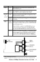
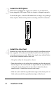
3 Install the SFP Optics The R752-1S and R752-SS require two or three sets of small formfactor pluggable (SFP) optics. Each set of optics is shipped separately. To install the optics, slide the SFP module into an empty slot, pushing it firmly in place. Remove the protective covering on the LC connectors. 1000 BASE PWR RESET 4 M A I N LK AT P R I LK AT S E C LK AT SW SEC Install the Line Card Radiance line cards offer the ease of plug-and-play installation and are hot-swappable.
Slot for Management Card Card Guide 10/100 10/100 PWR 100 RX LK x II TX x II FD RX T X LK TX LK 100 LK LK SX LK M M LK TX R X RX M M x II LK TX TX RESET MGT-10 PWR PWR LK LK PWR TX TX LK M M RX R X LK S M M M LK RX LK T X TX TX TX LX S M R X LK R X LK R X M M M M M M T X T X T X LK T P R X 100 FD AT TX PWR LK LK LK R X S M S M T X T X M M FX FD LK RX M M LX RX T X TX 100 LK T X OC-12 OC-12 PWR FL RX M M OC-12 PWR FL R
The R752-11 redundant interface line card provides two additional RJ45 jacks for the PRIMARY and SECONDARY port connections. Both ports support a maximum segment length of 100 meters over Category 5e twisted-pair cables.
transmit (TX) optical conductor of the device connects to the receive (RX) optical conductor of the Radiance card. Use the link (LK) LEDs on the front panel of the card to verify correct segment connectivity. As you insert the cable into each port, the LK LED will be lit if the following conditions are met: • Power is being applied to the chassis. • There is an active device connected to the other end of the cable, and it is sending idle link signals.
User Guide This section contains information regarding the operating features of your Radiance 1000Mbps redundant interface line card. LED Operation Several LEDs are visible from the front panel. These include the power (PWR), switchover (SW), secondary (SEC), link (LK) and activity (AT) LEDs. There are separate link and activity LEDs for each of the three ports. Refer to the table below for a description of each LED.
Reset Push Button A small RESET push button is located on the front panel of the Radiance redundant line card. When used in conjunction with the card’s switchover and secondary LEDs and the AUTO DIP switch setting, this push button allows you to effectively maintain or troubleshoot the PRIMARY link connection. Because of its small size and recessed placement within the front panel, press the RESET push button with the tip of a pointed object. Pushing and holding the RESET push button has no effect.
Link Loss Carry Forward (LLCF) The R752-SS redundant interface line card has been designed with LLCF functionality to aid in troubleshooting remote connections. When LLCF is enabled* and the R752-SS stops receiving link signals on a port, it stops the transmission of link signals on the other port of the line card. For example, if LLCF is enabled and two R752-SS redundant line cards are connected at the PRIMARY port with nothing else connected to them, their Link LEDs will not be lit.
Copper Loss Carry Forward (CLCF) The R752-1S copper-to-fiber card incorporates CLCF for identifying a lost copper connection. When CLCF is enabled*, the fiber port’s transmitter shuts down if the copper port stops receiving link pulses. The copper port, however, continually transmits link signals regardless of whether or not the fiber port receives link signals. The diagram below shows a typical network configuration with good link status using two R752-1S redundant line cards for remote connectivity.
Switch On No Activity Received (SONAR) The Radiance 1000Mbps redundant interface line card is designed to protect a network from failure that would prevent data from reaching its destination. With SONAR enabled, the line card monitors the active port for loss of data activity, in addition to loss of a valid link.
Back-to-Back Application A typical application of the 1000Mbps redundant interface line cards is to use them in pairs to extend a network’s reach between two remote devices. In this back-to-back setup, both PRIMARY ports are linked to each other and both SECONDARY ports are linked to each other as shown in the figure below.
Single Strand Fiber Failover Protection To ensure network resiliency in the event a single strand of fiber cable breaks or fails, the R752-1S and R752-SS (Rev B or higher) provide failover protection by automatically forcing both ports to switch from Primary to Secondary. This maintains the continuous flow of data in both directions. Scenario The diagram below shows two R752 redundant interface line cards connected together at the Primary and Secondary ports.
Solution To implement single-strand failover protection, enable the following DIP switches*: RED, LINK, AUTO, and TX on each card. The R752 line cards automatically perform the following operations to restore data activity. • Line Card A switches its active port from Primary to Secondary. • Line Card A stops transmitting data and link pulses through the Primary port. • Line Card B switches its active port from Primary to Secondary. Bi-directional traffic is now restored.
Topology Solution Server Cluster A Server Cluster B Servers with 1000Mbps NICs PC running Network Management Software Radiance R5000 with Redundant Interface Line Cards Secondary F/O Link B Primary F/O Link A Secondary F/O Link A Primary F/O Link B 1000Mbps F/O Switch Enterprise Switch 22 User Guide 1000Mbps F/O Switch
Changing the SFP Transceiver Depending on the model, the fiber ports on 1000Mbps redundant interface line card supports two or three replaceable small form-factor pluggable (SFP) transceivers. This section explains how to remove and install the parts into the card. Metrobility SFP transceivers are hot-swappable and can be changed without disrupting traffic on the other ports. IMPORTANT: Use only Metrobility SFP transceivers with this product.
Technical Specifications Data Rate Full duplex ______________________________________________ 1000Mbps Power Requirements R752-11 ______________________________________ 5V DC @ 1.4A, 7.0W R752-1S ______________________________________ 5V DC @ 1.1A, 5.5W R752-SS _____________________________________ 5V DC @ 0.84A, 4.
Singlemode Fiber Optic Plug-in (O211-10) Connector _____________________________________________________ LC Wavelength ________________________________________________ 1310nm RX Input Sensitivity _______________________________ -20 dBm to -3 dBm Output Power ____________________________________ -9.
Singlemode Fiber Optic Plug-in (O211-1A) Connector _____________________________________________________ LC Wavelength ________________________________________________ 1550nm RX Input Sensitivity _______________________ -32 dBm to -3 dBm minimum Output Power _______________________________________ 0 dBm to 5 dBm Typical Link Budget _________________________________________ 36 dBm Supported Link Length ___________________________________ up to 100km Cable Type _____________________________________ 9/125 µm s
Product Safety, EMC and Compliance Statements This equipment complies with the following requirements: • UL • CSA • EN60950 (safety) • FCC Part 15, Class A • EN55022 Class A (emissions) • DOC Class A (emissions) • EN55024: 1998 (immunity) • IEC 825-1 Classification • Class 1 Laser Product This product shall be handled, stored and disposed of in accordance with all governing and applicable safety and environmental regulatory agency requirements.
Warranty and Servicing Three-Year Warranty for the Radiance 1000Mbps Redundant Interface Line Card Metrobility Optical Systems, Inc. warrants that every Radiance 1000Mbps redundant interface line card will be free from defects in material and workmanship for a period of THREE YEARS from the date of Metrobility shipment. This warranty covers the original user only and is not transferable.
ADDITIONAL IMPORTANT WARRANTY INFORMATION: The Radiance 1000Mbps redundant interface line card is designed to operate using only the Metrobility small form-factor pluggable (SFP) transceivers specified in this manual. The use and installation of parts not included in this document will void the product’s warranty and may cause damage to the unit.
Product Manuals The most recent version of this manual is available online at http://www.metrobility.com/support/manuals.htm Product Registration To register your product, go to http://www.metrobility.com/support/registration.asp 25 Manchester Street, Merrimack, NH 03054 USA tel: 1.603.880.1833 • fax: 1.603.594.2887 www.metrobility.