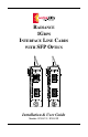
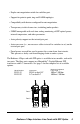
RADIANCE 1GBPS INTERFACE LINE CARDS WITH SFP OPTICS 1000 BASE 1000 BASE PWR PWR LK LK 1 1 AT AT LK LK 2 2 AT AT Installation & User Guide Models: R153-1S / R153-SS
Radiance 1Gbps Interface Line Cards with Small Form-Factor Pluggable (SFP) Optics Line Cards: R153-1S ______ 1000BASE-T RJ-45 to 1000BASE-X LC R153-SS ______ 1000BASE-X LC to 1000BASE-X LC SFP Optics: O211-M5 ______ SFP LC (multimode, 550 m 50 µm; 275 m 62.
Table of Contents Radiance 1Gbps Interface Line Cards with SFP Optics Installation & User Guide Overview ............................................................................................................. 4 Installation Guide ................................................................................................ 6 STEP 1: Unpack the Line Card ................................................................ 6 STEP 2: Set the DIP Switches ..................................................
Overview The Radiance R153 1Gbps interface line card with Small Form-Factor Pluggable (SFP) optics provides an affordable and flexible solution for the creation or expansion of high capacity fiber networks. A wide range of interchangeable optics offers maximum versatility and support for Gigabit Ethernet connectivity across multiple fiber types and distances. Advanced SFP port monitoring features help to ensure network reliability.
• Duplex auto-negotiation switch for each fiber port. • Support for point-to-point, ring and OADM topologies. • Compatibility with devices configured for auto-negotiation. • Transparency to data frame sizes, including jumbo packets. • SNMP manageable with real-time analog monitoring of SFP optical power, internal temperature, and other parameters. • Auto-polarity support on the twisted-pair port. • Auto-crossover (i.e., no crossover cables to install or switches to set) on the twisted-pair port.
Installation Guide Follow the steps outlined in this section to install and start using the Radiance 1Gbps interface line card with SFP optics. NOTE: Electrostatic discharge precautions should be taken when handling any line card. Proper grounding is recommended (i.e., wear a wrist strap). 1 Unpack the Line Card 2 Set the DIP Switches Your order has been provided with the safest possible packaging, but shipping damage does occasionally occur.
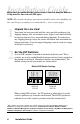
Link Loss Return (LLR) Switch The Radiance 1Gbps line card offers Link Loss Return functionality as an aid in troubleshooting remote fiber connections. When LLR is enabled on a fiber port, loss of link by the port’s receiver disables its own transmitter from sending out link pulses. LLR is enabled independently on each fiber port and is not applicable to the copper port. LLR2 enables/disables Link Loss Return on Port 2. LLR1 enables/ disables the function on Port 1 of the R153-SS.
Auto-Negotiation (AUTO) Switch The auto-negotiation switch is applicable only to the fiber ports and is enabled independently on each port. When AUTO is enabled, the fiber port advertises full duplex capability and the mode of operation is determined through the auto-negotiation process. By default, AUTO is enabled (UP position). When AUTO is disabled, the duplex mode is fixed at full duplex. Use AUTO1 to set autonegotiation on Port 1 and AUTO2 for Port 2.
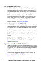
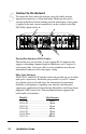
4 Install the Line Card The Radiance line card offers the ease of plug-and-play installation and is hot-swappable. The card must be secured firmly to the chassis before making network connections. Follow the simple steps outlined below to install the 1Gbps interface line card. • Grasp the card by the front panel as shown.
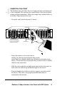
5 Connect to the Network To connect the line card to the network, insert the cables into the appropriate connectors as illustrated below. Make sure the card is secured to the chassis before making network connections. Once power is applied to the unit, correct connectivity can be verified via the link (LK) LED, which will be lit.
For more detailed information about the optics, refer to the Technical Specifications. IMPORTANT: The Radiance 1Gbps interface line card is designed to operate using only the Metrobility SFP transceivers listed in this document. Installing unspecified parts may damage the product and will void the unit’s warranty.
User Guide This section contains information regarding the operating features of the Radiance 1Gbps interface line card with SFP optics. LED Operation Several LEDs are visible from the front panel. These include the power (PWR), link (LK) and activity (AT) LEDs. There are separate link and activity LEDs for each port. Refer to the table below for a description of each LED. The function of each LED is as follows: LED Label Color (Status) Indication PWR Green (steady) Power is ON.
Fiber Optic Power Monitors Through software*, you can read the receive (RX) and transmit (TX) power levels on the 1Gbps line card’s fiber optic port(s). The accuracy of the RX and TX monitors is ±5%. Receive Power Level The RX power monitor shows a reading between -40 dB and 0 dB. Transmit Power Level The TX power monitor shows a reading between -16 dB and +11 dB. Internal Temperature Reading Through software, you can obtain the internal temperature reading for Port 2.
Link Loss Return (LLR) The fiber ports on the Radiance 1Gbps interface line card have been designed with Link Loss Return functionality for troubleshooting remote connections. When LLR is enabled*, the port’s transmitter shuts down if its receiver fails to detect a valid link signal. LLR should only be enabled on one end of a cable and is typically enabled on either the unmanaged or remote device. LLR works in conjunction with LLCF and CLCF.
Link Loss Carry Forward (LLCF) The Radiance R153-SS line card incorporates LLCF for troubleshooting a remote connection. When LLCF is enabled*, the ports do not transmit a signal until they receive a signal from the opposite port. When a lost link signal is returned to an unmanaged line card, that lost link must then be carried forward to a managed device (switch/hub) for trap generation.
Copper Loss Carry Forward (CLCF) The R153-1S copper-to-fiber card incorporates CLCF for identifying a lost copper connection. When CLCF is enabled*, the fiber port’s transmitter shuts down if the copper port stops receiving link pulses. The copper port, however, continually transmits link signals regardless of whether or not the fiber port receives link signals. The diagram below shows a typical network configuration with good link status using two R153-1S line cards for remote connectivity.
Topology Solutions Servers Switch PC running Network Management Software Radiance R5000 Central Service Platform with Gigabit Single Interface Line Cards Workgroup Hub remote connection — singlemode Switch Enterprise Switch Enterprise Copper Links Fiber Optic Links Coarse Wavelength Division Multiplexing (CWDM) Using the CWDM optics, the R153 line cards can be integrated into a Radiance CWDM system, in which a single fiber pair carries data bidirectionally on multiple wavelengths.
RING TOPOLOGY Radiance R4000 with 4-Channel CWDM Mux/Demux Modules Radiance R5000 with R153 Line Cards Central Office Radiance R4000 with OADM Modules Drop & Pass Radiance R1000 with R153 Line Cards Radiance R4000 with OADM Modules Drop & Insert Drop & Pass Radiance R1000 with R153 Line Card Radiance R1000 with R153 Line Card Radiance R4000 with OADM Modules Drop & Insert Radiance R1000 with R153 Line Cards 18 User Guide Radiance R4000 with OADM Modules Drop & Pass Radiance R1000 with R153 Li
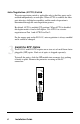
Changing the SFP Optics Depending on the model, the 1Gbps interface line card supports one or two replaceable small form-factor pluggable (SFP) transceivers for the fiber port(s). This section explains how to remove and install the optics on the card. Metrobility SFP transceivers are hot-swappable and can be changed without disrupting traffic on the other port. IMPORTANT: Use only Metrobility SFP transceivers with this product.
Technical Specifications Data Rate Full duplex _________________________________________________ 1Gbps Power Requirements Power __________________________________________ 5 V DC @ 1 A, 5 W Environmental Operating Temperature _____________________________________ 0 to 50° C Storage Temperature _____________________________________ -30 to 70° C Operating Humidity _________________________ 5% to 95% non-condensing Weight _______________________________________________ 5 oz (0.
Singlemode Fiber Optic Plug-in (O211-10) Connector _____________________________________________________ LC Wavelength _______________________________________________ 1310 nm RX Input Sensitivity _______________________________ -20 dBm to -3 dBm Output Power ____________________________________ -9.
Singlemode Fiber Optic Plug-in (O211-1A) Connector _____________________________________________________ LC Wavelength _______________________________________________ 1550 nm RX Input Sensitivity _______________________________ -32 dBm to -3 dBm Output Power _______________________________________ 0 dBm to 5 dBm Typical Link Budget _________________________________________ 36 dBm Supported Link Length __________________________________ up to 100 km Cable Type _____________________________________ 9/125 µm s
Acronyms and Abbreviations AT AUTO CLCF CWDM dB dBm Demux FX Gbps GigE km LED LK LLCF LLR Mux nm OADM PWR RX SFP Activity Auto-negotiation Copper Loss Carry Forward Coarse Wavelength Division Multiplexing Decibel Decibels relative to 1 mW of power (0 dBm equals 1 mW) Demultiplexer Ethernet over fiber Gigabits per second Gigabit Ethernet Kilometer Light emitting diode Link Link Loss Carry Forward Link Loss Return Multiplexer Nanometer Optical Add/Drop Module Power Receive Small Form-Factor Pluggable Radian
Product Safety, EMC and Compliance Statements This equipment complies with the following requirements: • UL • CSA • EN60950 (safety) • FCC Part 15, Class A • EN55022 Class A (emissions) • DOC Class A (emissions) • EN55024: 1998 (immunity) • IEC 825-1 Classification • Class 1 Laser Product This product shall be handled, stored and disposed of in accordance with all governing and applicable safety and environmental regulatory agency requirements.
Warranty and Servicing Three-Year Warranty for the Radiance 1Gbps Line Card Metrobility Optical Systems, Inc. warrants that every Radiance 1Gbps interface line card will be free from defects in material and workmanship for a period of THREE YEARS from the date of Metrobility shipment. This warranty covers the original user only and is not transferable.
ADDITIONAL IMPORTANT WARRANTY INFORMATION: The Radiance 1Gbps line card is designed to operate using only the Metrobility small form-factor pluggable (SFP) transceivers specified in this manual. The use and installation of parts not included in this document will void the product’s warranty and may cause damage to the unit.
Radiance 1Gbps Interface Line Cards with SFP Optics 27
Product Manuals The most recent version of this manual is available online at http://www.metrobility.com/support/manuals.htm Product Registration To register your product, go to http://www.metrobility.com/support/registration.asp 25 Manchester Street, Merrimack, NH 03054 USA tel: 1.603.880.1833 • fax: 1.603.594.2887 www.metrobility.