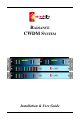
RADIANCE CWDM SYSTEM Installation & User Guide
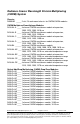
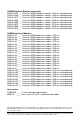
Radiance Coarse Wavelength Division Multiplexing (CWDM) System Chassis: R4000-02 _____ 2-slot 1U rack-mount chassis for CWDM/OADM modules CWDM Multiplexer/Demultiplexer Modules: R416-A4-A ____ 4-channel CWDM mux/demux module w/expansion, 1550, 1570, 1590, 1610 nm R416-A4-B ____ 4-channel CWDM mux/demux module w/expansion, 1470, 1490, 1510, 1530 nm R416-A4-C ____ 4-channel CWDM mux/demux module w/expansion, 1390, 1410, 1430, 1450 nm R416-A4-D ____ 4-channel CWDM mux/demux module w/expansion, 1310, 1330, 1350
OADM Drop/Pass Modules (continued): R426-D4-47E __ 1-channel OADM drop/pass module, 1470 nm, extended temp R426-D4-49E __ 1-channel OADM drop/pass module, 1490 nm, extended temp R426-D4-51E __ 1-channel OADM drop/pass module, 1510 nm, extended temp R426-D4-53E __ 1-channel OADM drop/pass module, 1530 nm, extended temp R426-D4-55E __ 1-channel OADM drop/pass module, 1550 nm, extended temp R426-D4-57E __ 1-channel OADM drop/pass module, 1570 nm, extended temp R426-D4-59E __ 1-channel OADM drop/pass module, 15
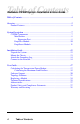
Table of Contents Radiance CWDM System Installation & User Guide Table of Contents ................................................................................................. 4 Overview ............................................................................................................... 5 Product Features ............................................................................................ 6 System Description ..........................................................................
Overview The Radiance Coarse Wavelength Division Multiplexing (CWDM) System is a passive, optical solution for increasing the flexibility and capacity of existing fiber lines in high-speed networks. By adding more channels onto available fibers, the Radiance CWDM System enables greater versatility for data communications in ring, point-to-point, and multipoint topologies for both enterprise and metro applications.
modified in a user-friendly format. The chassis and modules appear as an inventory device with matching colored ports. Product Features The Radiance CWDM System provides the following key features: • ITU G.694.2 CWDM wavelength grid with 20 nm spacing. • Support for up to 16 different channels, each carrying 1 Gbps of bandwidth. • Expansion port on all 4-channel mux/demux modules. • Color-coded port labels for easy identification. • SC connectors.
System Description This section describes the components of the Radiance CWDM System. CWDM Components The Radiance CWDM System is comprised of three basic components. • The multiplexer/demultiplexer (mux/demux) combines four or eight different channels onto a common network fiber. Data received from the network fiber is separated back into the individual channels and returned to the local ports.
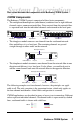
Mux/Demux The mux/demux provides four interface ports, each mapped to a different wavelength. The mux/demux combines the channels and transmits them on a single outbound (TX) fiber. Simultaneously, the mux/demux receives the same four channels from a single inbound (RX) fiber, separates them into individual wavelengths, and delivers each to the appropriate local interface. This process quadruples the capacity of the existing network fiber cable.
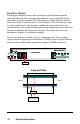
The next diagram illustrates how the channels for the example above are cascaded through the expansion port. Mux/Demux #1 is transporting 8 different channels, and Mux/Demux #2 is transporting 12 channels on its network fiber. Mux/Demux #2 Local Interfaces R X = T X Exp WEST = Channels 1-12 EAST Local Interfaces Mux/Demux #1 R X = T X Channels 1-8 The Radiance CWDM System supports four 4-channel mux/demux modules and one 8-channel mux/demux.
Drop/Pass Module The drop/pass module removes one wavelength-specific channel from the eastbound fiber and allows the remaining channels to pass straight through to other nodes along the network. When the drop/pass module drops the channel from the network, it sends the data to a local interface.
Drop/Insert Module The drop/insert module provides two local interface ports. One port removes a wavelength-specific channel from the network fiber in one direction, and the other port adds that same channel back onto the fiber in the opposite direction. Because the drop/insert module supports two separate pathways going in opposite directions, network viability in a ring topology is ensured even if there is a break in the network.
Installation Guide Follow the steps outlined in this section to install and start using the Radiance CWDM System.
2 Mount the Chassis The R4000 is intended for use in an office or industrial environment with the chassis installed in a standard equipment rack. Use the 6-32 self-tapping screws included with the R4000 to secure the mounting brackets to the side panel. You will need four (4) additional screws (not included with the R4000) to mount the chassis into the rack. Make sure that the mounting of the R4000 does not create a hazardous condition due to an unbalanced load.
3 Attach the Grounding Lug 4 Connect to the Network 14 On the back panel, the R4000 provides two vertical grounding points where a grounding lug may be installed. Use a Panduit® copper, standard barrel, two-hole lug (part number LCD8-10A-L) or its equivalent. Use two 10-32 screws to fasten the lug to the chassis. Use a No. 8 AWG copper wire to connect the lug to the grounding point at your site.
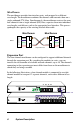
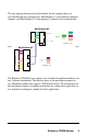
CWDM 1450 1430 1370 1350 TX RX MUX/DEMUX EXPANSION RX NETWORK Receivers Transmitters TX Port receivers (RX) are located above their corresponding transmitters (TX). For proper connectivity, make sure that the module’s receiver connects to the transmitter on the system device, and that the receiver on the system device connects to the Radiance module’s transmitter. There are three types of ports on the CWDM/OADM modules.
Connecting to the Network Use the Network Port for backbone connectivity. The mux/demux modules have one network port, which alternatively may be connected to an expansion port (see below). The OADM modules provide two network ports for connectivity to the east and west. Connect the singlemode fiber from the west backbone to the module’s WEST Network Port, and connect the singlemode cable from the east backbone to the module’s EAST Network Port.
User Guide This section contains more detailed information about using the Radiance CWDM System. Calculating the Transmission Power Budget When designing an optical link, one of the factors to consider is the transmission power budget. The power budget is required for determining the maximum distance a link can support. The transmission power budget is the difference between the optical transmitter output power and the receiver sensitivity: Power Budget = TX Power - RX Sensitivity [EQ.
Power Budget = TX Power - RX Sensitivity - Losses TX Power = 2 dBm RX Sensitivity = -25 dB Losses = (8-channel Mux/Demux #1 loss) + (4-channel Mux/Demux #2 loss) + (4-channel Mux/Demux #3 loss) + (8-channel Mux/Demux #4 loss) = 2.5 dBm + 2.0 dBm + 2.0 dBm + 2.5 dBm = 9.0 dBm Power Budget = TX Power - RX Sensitivity - Losses = 2 dBm - (-25 dBm) - 9.0 dBm = 18 dBm Example 3: Calculate the power budget for Link B in the following diagram.
Calculating the Maximum Link Distance After you have determined the power budget for a fiber link, you can use that value to calculate the maximum distance the link will support. Power Budget - Buffer Distance = _________________________________ [EQ. 3] Fiber Attenuation Typically, a buffer of 2 dBm is subtracted from the power budget to account for other factors that may affect the loss of transmission power. These factors include fiber aging, temperature, humidity, poor splices, etc.
Software Support Metrobility’s NetBeacon software (version 3.5 and above) supports the Radiance R4000 chassis and CWDM/OADM modules. After you enter the system and configuration information through a special dialog box, NetBeacon automatically archives the information in its server database. The NetBeacon Server maintains a general inventory of all R4000 chassis entered by all NetBeacon Clients. The inventory is accessible by any NetBeacon Client.
Topology Solutions Colored lines are used to represent different CWDM channels in all topology examples.
RING TOPLOGY Radiance R4000 with two 4-Channel Mux/Demux Modules Drop & Insert Drop & Insert Radiance R4000 with two 4-Channel Mux/Demux Modules Radiance R5000 with R153 Line Cards Radiance R5000 with R153 Line Cards Drop & Insert Radiance R4000 with two 4-Channel Mux/Demux Modules Radiance R5000 with R153 Line Cards The network connections in the following examples are shown in gray with the magnification circles displaying the channels carried on the network fiber.
REDUNDANCY AND PROTECTION TOPLOGY Router Radiance R5000 with R153 Line Cards Central Office Radiance R4000 with 4-Channel CWDM Mux/Demux Modules Radiance R1000 with R153 Line Cards Radiance R4000 with Drop/Insert Module Drop & Insert Drop & Insert Radiance R4000 with Drop/Insert Module Radiance R1000 with R153 Line Cards Drop & Insert Radiance R4000 with Drop/Insert Module Radiance R1000 with R153 Line Cards Radiance CWDM System 23
Replacing a Module This section describes how to replace a module in the R4000 chassis. 1. If there are any fiber optic cables installed, disconnect them from the module. WARNING: Avoid looking into the laser beam coming from the cable. 2. Turn the two thumb screws counterclockwise several times to loosen the module from the chassis. OADM DROP/PASS 1550 Turn thumb screw counterclockwise to loosen. NETWORK DROP TX NETWORK RX WEST RX EAST TX Thumb Screws Turn thumb screw clockwise to tighten. 3.
Technical Specifications Environmental Operating Temperature ____________________________________ 0° to 50° C Extended Operating Temperature† ____________________________________________ -40° to 80° C Operating Humidity _________________________ 5% to 95% non-condensing Physical Physical Case _________________________ Fully enclosed metal construction Dimensions Chassis ______________________________ 10.0" L x 17.0" W x 1.72" H _______________________________ 25.4 cm x 43.2 cm x 4.
Model Number Wavelength Model Number Wavelength O411-80-31 1310 nm O411-80-47 1470 nm O411-80-33 1330 nm O411-80-49 1490 nm O411-80-35 1350 nm O411-80-51 1510 nm O411-80-37 1370 nm O411-80-53 1530 nm O411-80-39 1390 nm O411-80-55 1550 nm O411-80-41 1410 nm O411-80-57 1570 nm O411-80-43 1430 nm O411-80-59 1590 nm O411-80-45 1450 nm O411-80-61 1610 nm 26 User Guide
Abbreviations ACT CWDM dB dBm Demux Gbps GigE ITU km Mbps Mux nm OADM RX SFP SNMP TX Activity Coarse Wavelength Division Multiplexing Decibels Decibels relative to 1 mW of power (0 dBm equals 1 mW) Demultiplexer Gigabits per second Gigabit Ethernet International Telegraphic Union Kilometer Megabits per second Multiplexer Nanometer Optical Add/Drop Multiplexing Receive Small Form-Factor Pluggable optical transceiver Simple Network Management Protocol Transmit Product Safety and Compliance Statements This e
Warranty and Servicing Three-Year Warranty for the Radiance CWDM System Metrobility Optical Systems, Inc. warrants that every Radiance CWDM System (R4000 chassis and modules) will be free from defects in material and workmanship for a period of THREE YEARS from the date of Metrobility shipment. This warranty covers the original user only and is not transferable.
Notes Radiance CWDM System 29
Product Manuals The most recent version of this manual is available online at http://www.metrobility.com/support/manuals.htm Product Registration To register your product, go to http://www.metrobility.com/support/registration.asp 25 Manchester Street, Merrimack, NH 03054 USA tel: 1.603.880.1833 • fax: 1.603.594.2887 www.metrobility.