
Operating instructions
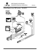


AVR Pellet Control Board
Installation/Service Instructions
250-00011
Page 1 of 2 Printed 1/24/06
Compatibility
• Avalon Newport PS and Newport Bay PI (Avanti PS & PI)
• Avalon Astoria PS and Astoria Bay PI
• Lopi Pioneer PS and Pioneer Bay PI (Heritage PS & PI)
• Lopi Yankee PS and Yankee Bay PI
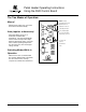
Packing List
• Control Board (AVR Design)
• Molex Jumper
Overview
The new AVR control board is the next generation control board that is compatible with all pellet stoves and
inserts, large and small manufactured from 1997 to today. Circuitry on the board allows it to be programmed
for either the large or small pellet heaters (these heaters use different voltage settings). See “Configuring the
Control Board“ for details. It also includes a diagnostic feature that allows a service person to diagnose a
fault without having to inspect the wiring or components. The indicator lights on the control board will display
a fault code after a fault has been detected. This allows the service person to determine which component
caused the fault. See “Diagnostic Codes” for details. NOTE: the new wiring harness (250-00017) is required
to utilize this feature.
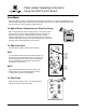
Configuring the Control Board
Configuring for Large or Small Heaters
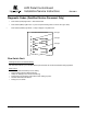
The control board is initially configured for the large heaters (Astoria and Yankee models). To change the
configuration the control board must be in the off position plugged into a cold stove, (no lights or running
components) with the jumper molex removed (see the illustration below). In this condition press and hold the
manual auger button down and press both fan up and fan down arrow keys at the same time. All heat output
lights will flash. One flash denotes the large pellet
heater configuration. Two flashes denote the small pellet heater
configuration
(Newport and Pioneer models). Repeat pressing the keys until the correct configuration is obtained.
250-00012
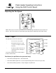
Using this Control Board with Older Wiring Harnesses
When the control board is installed on an older wire harness the 4 pin molex jumper plug on the back of the
control board next to the stock wire harness must be installed. This jumper replaces the diagnostic wires (see
“Wiring Diagram”) that are present on the new wiring harness. The control board will work normally, but the
diagnostic capabilities will not function.