TRAVIS INDUSTRIES TRAINING YOUR SUCCESS IS OUR BUSINESS Pellet Appliance Troubleshooting Guide Copyright © 4/20/2006 Travis Industries, Inc.
Appliance Operation Principles Pellet Appliance Operation Sequence 1-2 Auger Feed Rate Timing 3 Power Outages 4-5
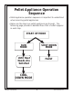
Pellet Appliance Operation Sequence • Pellet appliance operation sequence is important to understand • when servicing pellet appliances. • Below are the steps our pellet appliances go through. The • • • • following page provides a detailed flow chart of what happens • in each step. START UP MODE RUN MODE SHUT DOWN MODE Until Heat Needs Are Satisfied FAULT COOL DOWN MODE Copyright © 4/20/2006 1 Travis Industries, Inc.
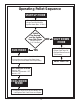
Operating Pellet Sequence START UP MODE • Exhaust Blower On High • Auger Feed On Medium • Ignitor Heats (Max. 30 Min.
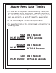
Auger Feed Rate Timing • The feed rate of the pellets is determined by the ON/OFF • cycling of auger motor. Remember the auger motor turns • at a constant speed of 1 RPM. Therefore, to vary the pellet • feed, we control the on and off time of the auger motor.
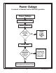
Power Outage In manual or Remote Control (ON/OFF) operation Power Outage Pellet Appliance Stops Power Comes On System Disk Still Hot “Closed” NO Fault Light Comes On YES Pellets Feed • Pellets Pile Up Enough coals in the burnpot to ignite new pellets NO • System Disk • Cools “Open” • Fault Light • Comes On YES Pellet Appliance Continues To Run Copyright © 4/20/2006 4 Travis Industries, Inc.
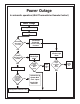
Power Outage In automatic operation (Wall Thermostat or Remote Control) Power Outage Pellet Appliance Stops Power Comes On Thermostat Still Calling For Heat NO Thermostat Eventually Closes Calling For Heat YES System Disk Still Hot “Closed” NO System Goes Into Re-Light Mode System Goes Into Relight Mode Pellets Light & System Disk Closes YES Pellets Feed NO Fault Light Comes On Pellets Light & System Disk Closes NO Fault Light Comes On YES YES Enough coals in the burnpot to ignite new pelle
Pellet Troubleshooting Flow Chart Pellet Troubleshooting Flow Chart 1-3
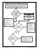
With the appliance ON/OFF switch off, unplug and replug the power cord Convection Fan or Exhaust Blower Comes On • Continuity test convection blower • BAD - Replace • GOOD - Continuity test pathway •from - pin #5 - to the end of the brown wire • - From pin #7 to the end of the white wire • Check system disk for closed • when it should be open • If everything is GOOD - Replace board NO START UP MODE Power Up Unit & Push Start Button YES Board Lights Up YES Exhaust Blower On NO NO • Check 110V supply
• Check for pinched vacuum hose or blocked hose on flow switch • (Tube & barbed connector) Auger Turning NO • Continuity test auger motor • BAD - Replace • GOOD - Check pathway (check continuity from pin #6 to end of RED power wire, check Snap Disk(s) continuity, check Flow Switch, check pin #7 to the end of WHITE wire YES • BAD - Replace defective item(s) • GOOD - Replace bBoard • Continuity test igniter Igniter On NO • BAD - Replace • GOOD - Continuity test pathway - #1 Pin to BLACK Wire - #7 • P
RUN MODE • Continuity test blower • BAD - Replace Convection Blower On NO • GOOD - Continuity test pathway - from pin #5 - to the end of the BROWN wire - from pin #7 to the end of the WHITE wire • GOOD - Replace board • Convection blower will not • vary speed - Replace board YES Feed Rate and Blower Speed Varies NO • Replace Board END Copyright © 4/20/2006 3 Travis Industries, Inc.
Troubleshooting Testing Configuring the New Pellet Control Board 1-5 Wiring Diagram 6-7 Control Board Operation 8-13 General Troubleshooting Tips 14 Required Testing Equipment 15-16 Power Cord Testing Pellet Components 17-18 Continuity Testing Pellet Stove Components 19-20 Continuity Testing Wiring Harness 21-24 New Pellet Board Auger Timing 25
Configuring the Control Board Overview The new AVR control board is the next generation control board that is compatible with all pellet stoves and inserts, large and small manufactured from 1997 to today. Circuitry on the board allows it to be programmed for either the large or small pellet heaters (these heaters use different voltage settings). See ““ for details. It also includes a diagnostic feature that allows a service person to diagnose a fault without having to inspect the wiring or components.
Configuring the Control Board Using this Control Board with Older Wiring Harnesses When the control board is installed on an older wire harness the 4 pin molex jumper plug on the back of the control board next to the stock wire harness must be installed. This jumper replaces the diagnostic wires (see “”) that are present on the new wiring harness. The control board will work normally, but the diagnostic capabilities will not function.
Configuring the Control Board Diagnostic Codes (Qualified Service Personnel Only) • Fault and #2 (LOW) Light Flash = Flow Switch Fault • Fault and # 4 (MED) Light Flash = System Snap Disk Fault (pellets run out & stove goes cold) • Fault and # 6 (HIGH) Light Flash = Safety or Hopper Snap Disk Fault Flow Switch Fault Fault light and #2 heat indicator blinking. This fault code indicates pressure/flow switch opened or broke its electrical connection during operation.
Configuring the Control Board Diagnostic Codes (Qualified Service Personnel Only) - Continued System Snap Disk Fault Fault light and #4 heat indicator blinking. This fault code is caused by a heat sensitive switch that tells the control board if the appliance is hot or cold. During operation if the unit runs out of pellets or looses its fire this switch will communicate to the control board that the stove is getting cold.
Configuring the Control Board Diagnostic Codes (Qualified Service Personnel Only) - Continued Safety or Hopper Snap Disk Fault Fault light and #6 heat indicator blinking. This fault code is caused by the safety or hopper snap disk registering an over-heated appliance during operation. The control board then shuts down the auger and the convection and combustion blower will run at maximum output for a 40 minute safety cool down cycle.
Wiring Diagram (New, 2005 Version - 250-00017) Copyright © 4/20/2006 6 Travis Industries, Inc.
Wiring Diagram (Old Version - 100-00393B) NOTE: Wire coloring may not be identical to this diagram Copyright © 4/20/2006 7 Travis Industries, Inc.
Control Board Operation The Two Modes of Operation: Manual Manual mode requires the user to turn the heater on and off manually. Auto (requires a thermostat) Auto mode allows you to use a thermostat to control room temperature. The stove automatically turns on when the temperature drops below the thermostat setting. Once the stove reaches operating temperature, the stove then runs at the heat output setting selected.
Control Board Operation Manual Mode Manual mode requires the user to turn the heater on and off manually. To Start Press the "Manual Start" button. That's it. The stove automatically goes to a medium burn rate and high fan while the igniter starts the fire burning within 10 minutes. During this period the lowest “HEAT OUTPUT” light will flash. If the stove does not start in 30 minutes, the stove turns off.
Control Board Operation To Shut Down Move the mode switch to "OFF". The exhaust blower will still run until the heater cools down. To Adjust the Heat Press the "Heat” buttons to adjust the heat output. NOTE: During start-up you may adjust the heat setting. This heat setting will take affect once the start-up sequence is complete. Copyright © 4/20/2006 10 Travis Industries, Inc.
Control Board Operation Auto Mode Auto mode allows you to use a thermostat to control room temperature. The stove automatically turns on when the temperature drops below the thermostat setting. Once the stove reaches operating temperature, the stove then runs at the heat output setting selected. To Adjust Room Temperature (or Start the Stove) Move the thermostat to the heat setting desired. If the room is cooler than the setting, the stove will go through the start-up sequence for approximately 10 minutes.
Control Board Operation To Shut Down Move the mode switch to "OFF". The exhaust blower will still run until the heater cools down. Adjusting the Fan Speed NOTE: When you press the Fan speed buttons the “Heat Output” lights will indicate fan speed (not “Heat Output”). After a few seconds the “Heat Output” lights will go back to displaying the heat output setting. Copyright © 4/20/2006 12 Travis Industries, Inc.
Control Board Operation "FAULT" Light This light comes on when an error occurs: • The stove runs out of pellets • During initial start-up (for a split second) or for improper electricall • frequency • A start-up sequence that does not result in the heater coming up • to temperature • To reset the fault light, turn the mode switch to off and re-start • the stove. Copyright © 4/20/2006 13 Travis Industries, Inc.
Troubleshooting Pellet Appliances Troubleshooting Pellet Appliances • Mode Sequence • Ask What? • Unplug To Reset • Board • Move Through • • Modes of • • • • • • Operation • Self Diagnosis • Keep the operation sequence in mind. • Ask what should be working in • each mode and what should not.
Required Testing Equipment • Multimeter • Power Test Cord Kit & Jumper Wire • Outlet Analyzer • Volt Stick Copyright © 4/20/2006 15 Travis Industries, Inc.
Pellet Stove Component Testing Outlet Analyzer 110 Volt Outlet • Test the power outlet to verify proper polarity and • proper grounding. Short Side (Hot Side) Long Side (Neutral Side) Ground Copyright © 4/20/2006 16 Travis Industries, Inc.
Power Cord Testing Pellet Components • Connect power cord to • component, then plug the • power cord into a known, • working power outlet. • Convection Blower Small Pellet Stoves Large Pellet Stoves • Exhaust Blower Large Pellet Stoves Small Pellet Stoves • Auger Motor • Igniter Copyright © 4/20/2006 17 Travis Industries, Inc.
Power Cord Testing Copyright © 4/20/2006 18 Travis Industries, Inc.
Continuity Testing Pellet Components • TURN OFF ALL POWER • Disconnect at least on side • of the devise being tested to • • avoid the “Back Door Sneak!” • FLOW SWITCH (N. O.) • AUGER MOTOR Normally Open • 200˚ SNAP DISKS Convection & Hopper Snap Disk (N. C.) Normally Closed Copyright © 4/20/2006 19 120˚ System Snap Disk (N. O.) Normally Open Travis Industries, Inc.
Continuity Testing Pellet Components Small Pellet Stoves Large Pellet Stoves - Small Pellet Stoves Large Pellet Stoves NOTE; Do not continuity test igniter in the audible “BEEP’ meter mode, use the Ω (ohms) mode Copyright © 4/20/2006 20 Travis Industries, Inc.
Pellet Stove Continuity Component Testing Component Condition Good Condition Bad - Replace Auger Motor Continuity Across Wires No Continuity Across Wires Flow Switch (With Vacuum) Continuity Across Switch Contacts No Continuity Across Switch Contacts Igniter Continuity Across Wires No Continuity Across Wires System Disk: Porcelain Snap Disk F-120˚ F (N. O.
110 VAC POWER OFF! Switch Must Have Vacuum To Close Copyright © 4/20/2006 22 Travis Industries, Inc.
Molex Connector # System • The Molex connector is numbered, but hard to • read so... • With Molex connector turned so the cross member • A is at the top- The left side is odd # - The right side is even # A - The left side is odd # - The right side is even # Copyright © 4/20/2006 23 Travis Industries, Inc.
Continuity Testing Molex Connector & Wires MOLEX END 1 TEST TO WIRE END 1 CONTINUITY NO CONTINUITY GOOD DEFECTIVE 2 2 GOOD DEFECTIVE 3 3 GOOD DEFECTIVE 4 4 GOOD DEFECTIVE 5 5 GOOD DEFECTIVE 6 6 GOOD DEFECTIVE 7 7 GOOD DEFECTIVE 8 8 GOOD DEFECTIVE 3 7 5 1 6 4 2 8 Copyright © 4/20/2006 24 Travis Industries, Inc.
New Pellet Board Auger Timing Auger ON Time 2.5 Sec. LOW First Light Second Light Third Light Fourth Light Fifth Light Sixth Light OFF Time OFF Time OFF Time OFF Time OFF Time OFF Time 10.7 Sec. 7.5 Sec. 4.6 Sec. 3.8 Sec. 2.9 Sec. 2.2 Sec. Combustion Fan Volts Per Setting - Small Stoves LIGHT 1 2 3 4 5 6 LOW HIGH 68 AVC. 75 AVC.. 85 AVC. 95 AVC. 105 AVC.. 115 AVC. Combustion Fan Volts Per Setting - Large Stoves LIGHT 1 2 3 4 5 6 LOW HIGH 85 AVC. 95 AVC.. 105 AVC. 115 AVC. 115 AVC.. 115 AVC.
Troubleshooting Burn Problems Burn Characteristics 1 Burn Related Problem Matrix 2 Pellet Fuel 3
Troubleshooting Burn Characteristics Burn Characteristics NORMAL ABNORMAL • Bright orange flame • Pellet piling up • Slight “Popcorning” effect • of pellets • Excessive “Popcorning” • • • effect of pellets • Ash blowing out of burnpot • Unburnt or partially burnt • pellets blowing out of • • • • burnpot • Occasional ember blowing • out of burn pot • Excessive clinker buildup • • in burnpot • Soot deposits Copyright © 4/20/2006 1 Travis Industries, Inc.
Pellet Appliance Operation Problem Check List Burn Related Problems CHECK Door Gasketing Air Leak Glass Gasketing Air Leak Dirty Exhaust System Poor Pellets Dirty Burnpot Door Gasketing Air Leak Glass Gasketing Air Leak Restrictor Needs More Restriction Restrictor Needs Less Restriction Dirty Burnpot Dirty Exhaust System Air Wash Slots Blocked Excessive Clinker Buildup Excessive Ash Buildup Pellets Buildup Dirty Glass No Heat Auger Jam Copyright © 4/20/2006 CHECK Operator Error Client Expe
Thermostats & Remotes Appliance Does Not Work On Thermostat Setting 1 Testing Thermostats 2 Appliance Does Not Work On Remote Function 3 Wall Thermostat 4-5 Remote Control 6-8 Modulating Remote 9-15
Pellet Fuel Pellet Fuel • Travis pellet appliances are designed to burn • wood pellets. • Wood • The quality of the pellet fuel will dictate how • well the pellet appliance will perform. • Quality • Premium • • Grade • Pellet fuel with lots of fines and high ash • • content will produce maintenance and burn • problems • Therefore, we recommend that only premium • grade pellets be used (See Chart) (PFI) Pellet Fuel Institute Fuel Standards CRITERIA PREMIUM GRADE STANDARD GRADE 1. Bulk 1. density/cu.
Pellet Appliance Works on Manual But Not on Automatic (Thermostat) CHECK POSSIBLE CAUSE CORRECTIVE ACTION Control Board • Switch not in auto • position • Move to auto • position • Thermostat wires not • connected • Connect to control • • board • Improper setting • Set to proper setting Thermostat • Improper location • Remove heat • picking up heat from • source or move • • • • some other device • thermostat Control Board Copyright © 4/20/2006 • Defective • thermostat • Check and replace • • a
Testing the Thermostat Circuit • Make sure the unit control board switch is in the - automatic mode. Jumper Wire Test. - Jumper turns on fire. - Replace thermostat Jumper wire does not turn on fire.
Pellet Appliance Works on Manual But Not in Remote Mode (Remote Control) CHECK POSSIBLE CAUSE CORRECTIVE ACTION Operator • Not understanding • remote control • • • • • operation • Educate • Unrealistic • • • • • • • • expectations • Educate • Dead batteries • Replace • Not plugged into • control board • Plug in • DIP switches • • • • • • (frequency) do not • • match • Match sender and • • • receiver DIP switches • Remote sender in • • • position to pickup • • • heat from some other • source •
Pellet Wall Thermostat COMPATIBILITY • All Travis Gas Stoves & Inserts • Newport Pellet Stoves & Inserts • Pioneer Pellet Stoves & Inserts • Astoria Pellet Stoves & Inserts • Yankee Pellet Stoves & Inserts ITEMS NEEDED FOR ASSEMBLY • Standard Screwdriver • Additional tools may be required for laying the thermostat wire • You may need additional tools to access the on/off switch on certain gas heaters - refer to the instructions in the owner's manual.
Pellet Wall Thermostat Thermostat Placement and Installation 1. Determine a location for the thermostat that is within range of the 20' length of thermostat wire. It should be centralized in the room and away from the heater. The wire may be routed externally on the wall or behind the wall (preferred). Run the thermostat wire to this location. Use nylon ties, if necessary to keep the wire from contacting any hot portions of the heater. 2.
Pellet Remote Control &+(&.
Pellet Remote Control 3HOOHW 6WRYH ,QVWDOODWLRQ 3ODFH WKH UHFHLYHU KROGHU RQ WKH EDFN RI WKH KHDWHU DQG URXWH WKH UHFHLYHU ZLUHV WR WKH RQ RII VZLWFK VHH WKH LOOXVWUDWLRQ WR WKH ULJKW &RQQHFW WKH UHFHLYHU SRZHU FRUG WR D 9$& RXWOHW A $WWDFK WKH SHOOHW VWRYH FRQQHFWRU ZLUHV WR WKH HQGV RI WKH UHFHLYHU ZLUHV 7KHQ DWWDFK WKH FRQQHFWRU ZLUHV WR WKH EDFN RI WKH FLUFXLW ERDUG VHH WKH LOOXVWUDWLRQ WR WKH ULJKW D D 3ODFH WKH UHFHLYHU LQWR WKH KROGHU ZLWK WKH ZLUHV H[LWLQJ WKH UHDU E 3ODFH WKH KR
Pellet Remote Control 127( 7KH SLORW IODPH PXVW EH OLW WKH JDV FRQWURO YDOYH WXUQHG WR 21 DQG WKH RQ RII VZLWFK WXUQHG WR 2)) IRU WKH UHPRWH WR ZRUN FRUUHFWO\ 127( 7KLV NLW PXVW EH LQVWDOOHG E\ D TXDOLILHG WHFKQLFLDQ 0$18$/ 02'( 7+(50267$7 02'( 72 6(7 72 0$18$/ 8VH WKH DUURZ NH\V WR DGMXVW WKH WDUJHW WHPSHUDWXUH WR ) ) 6(7 7(03 7,0(5 5220 7(03 0,1 $X ) 6(7 7(03 7,0(5 5220 7(03 21 0,1 7LPH 6HW 7LPH 6HW 7LPH &DQFHO 7LPH &DQFHO R 2)) 72 6(7 72 7+(50267$7 02'( 8V
Pellet Modulating Remote COMPATIBILITY • Avalon Newport Stove & Insert • Lopi Pioneer Stove & Insert • Avalon Astoria Stove & Insert • Lopi Yankee Stove & Insert ITEMS NEEDED FOR ASSEMBLY • Three AAA Batteries PACKING LIST • Remote Receiver • Remote Control • Modulating Regulator • Torx T-20 Ball-End "L" Wrench • Stove Receiver Mounting Bracket • Fireplace Receiver Heat Shield FCC EQUIPMENT REQUIREMENTS WARNING: Changes or modifications to this unit not expressly approved by the party responsible for comp
Pellet Modulating Remote INSTALLATION INSTRUCTIONS 1 Remove the cover from the back of the transmitter. Slide the code switches to a random position on the receiver. Then position the switches on the transmitter to match the dip switch positions on the receiver. Prior to replacing the cover, place three AAA batteries inside the transmitter. Transmitter Receiver 1 2 3 4 DIP ON ON DIP C-P AAA Battery AAA Battery AAA Battery 1 2 3 4 1 2 3 4 ON ON DIP Receiver Dip Switches Slide the access cover off.
Pellet Modulating Remote 2 Follow the directions below to install the receiver. Make sure the appliance is unplugged before installing the remote receiver. a c Access the back of the circuit board (on stoves open the side panel - on inserts, remove the surround panel refer to the owner's manual for details). Attach the electrical connector from the receiver to the circuit board. Phillips Screwdriver Flow Switch b Yankee Pellet Stove place the remote receiver flat underneath the convection blower.
Pellet Modulating Remote BEFORE YOU BEGIN: Warning Read all of the safety precautions in the owner’s manual included with your heater before using this remote control. MODES OF OPERATION: The thermostat can be operated in the following modes: °F °F Manual Use the remote to turn the heater on and off. TO TURN THE HEATER ON PM AND OFF MANUALLY: Use the arrow keys to adjust (or 32° C).
Pellet Modulating Remote MODES OF OPERATION (continued): TO SET TO TIMED OPERATION: °F °F SET TEMP ROOM TEMP Timed Set the time you wish the heater to remain on. a) Press the “Set” button once. AUT O AA AA A AA AA A AA A AA b) Use the arrow keys to set the number of minutes you would like the heater to stay on (1 to 120 minutes). Fan Speed /O F F Heat Set Time Cancel c) Press the Auto On/Off switch until “Auto” appears.
Pellet Modulating Remote FEATURES (continued): °F °F SET TEMP ROOM TEMP Burn Rate Follow the instructions to the right to adjust the burn rate. : PM TO ADJUST THE BURN RATE: A UT O /O Fan Speed FF Heat Press on the “Heat” button to adjust Set the burn rate. The burn rate will Time Cancel toggle from the lowest burn rate (H1) to the highest burn rate (H6). TO ADJUST THE FAN SPEED: Press on the “Fan Speed” button to adjust the fan speed.
Pellet Modulating Remote SETTING THE TIME Hour and Minute Display “Set” Button °F °F SET TEMP ROOM TEMP PM AUT O / : Fan Speed O F F Heat Set Time Cancel Fahrenheit or Celcius Display (will display “F” or “C”) 1. Press and hold the “Set” button for 2 seconds. 2. The hour display will flash. Use the “Up” and “Down” buttons to set the hour. 3. Press the “Set” button again. 4. The minute display will flash. Use the “Up” and “Down” buttons to set the minute. 5. Press the “Set” button again. 6.
Restrictor Settings Restrictor Adjustment 1-2 Small Stoves & Inserts 3 Large Stoves 4-5 Large Inserts 6
Restrictor Adjustment Restrictor Adjustment • 15-20 Minute • Burn • Set On High Burn • Watch Burn • Activity • Adjust • Verify On Low • Burn • The appliance should be fully up • to temperature (15-20 Min.) before • attempting adjustment. • Turn the appliance to high. • Watch the burn pot activity to • • • • determine need for adjustment. • Adjust as necessary. • Turn heat setting to low to verify • it operates well on this setting.
Pellet Stove Restrictor Setting CONDITION Close the restrictor providing more restriction of air flow (Too much air) Open the restrictor less restriction of air flow (Too little air) Stove goes out on low burn Unburnt pellets are blowing out of burn pot Fly ash remains in the burn pot Pellet smoothers the fire Stove works fine during day but at night goes out leaving an unburnt pile of pellets (Due to cooler night temperature, draft in vent increases) Copyright © 4/20/2006 2 Travis Industries, Inc.
Small Stoves/Inserts Restrictor Setting Instruction Copyright © 4/20/2006 3 Travis Industries, Inc.
Large Stove Restrictor Setting Instruction - Yankee Copyright © 4/20/2006 4 Travis Industries, Inc.
Large Stove Restrictor Setting Instruction - Astoria Copyright © 4/20/2006 5
Large Insert Restrictor Setting Instruction Copyright © 4/20/2006 6 Travis Industries, Inc.
Troubleshooting Checklist Appliance Will Not Power Up 1 Pellets Will Not Feed 2-3 Pellets Do Not Light 4 Appliance Will Not Move Into Run Mode 5 Improper Burn Characteristics 6 Fault Light Comes On 7 Pellet Appliance Shuts Down 8 Dirty Glass 9 Lack of Heat 10 Thermostat Does Not Operate Stove 11 Remote Does Not Operate Stove 12 Ash Leakage 13 Sooting 14 Appliance Will Not Shut Off 15 Smoke In The House 16
Copyright © 4/20/2006 1 Travis Industries, Inc.
Copyright © 4/20/2006 2 Travis Industries, Inc.
Copyright © 4/20/2006 3 Travis Industries, Inc.
Copyright © 4/20/2006 4 Travis Industries, Inc.
Copyright © 4/20/2006 5 Travis Industries, Inc.
Copyright © 4/20/2006 6 Travis Industries, Inc.
Copyright © 4/20/2006 7 Travis Industries, Inc.
Copyright © 4/20/2006 8 Travis Industries, Inc.
Copyright © 4/20/2006 9 Travis Industries, Inc.
Copyright © 4/20/2006 10 Travis Industries, Inc.
Copyright © 4/20/2006 11 Travis Industries, Inc.
Copyright © 4/20/2006 12 Travis Industries, Inc.
Copyright © 4/20/2006 13 Travis Industries, Inc.
Copyright © 4/20/2006 14 Travis Industries, Inc.
Copyright © 4/20/2006 15 Travis Industries, Inc.
Copyright © 4/20/2006 16 Travis Industries, Inc.
Component Removal Auger Jam Removal 1 Auger Motor Replacement 2 Auger Replacement 3 Igniter Replacement 4-5 Exhaust Blower Replacement 6-7 Convection Blower Replacement 8-9 Fuse Replacement 10
Auger Jam Removal • Remove the six screws which hold down the auger cover and • remove the cover. Copyright © 12/13/2002 1 Travis Industries, Inc.
Auger Motor Replacement 1 2 • First remove the motor heat shield located on the right side of • the motor (picture #1) • Loosen the Hex Bolt on the locking collar (picture #2) 3 4 • Next loosen and remove the motor stop (picture #3) • Pull the motor (picture #4) Copyright © 4/20/2006 2 Travis Industries, Inc.
Auger Replacement 1 • Remove the four bolts holding the bearing housing (picture #1) Bearing Housing 3 • Remove the bearing housing in place (picture #3) Copyright © 4/20/2006 2 • Remove the locking collar (picture #2) 4 • Remove the auger flight (picture #4) 3 Travis Industries, Inc.
Igniter Replacement • Remove the convection blower and with a long extension, remove the 1/4” Hex Screw holding the igniter in place Copyright © 4/20/2006 4 Travis Industries, Inc.
Igniter Replacement • Remove the igniter Copyright © 4/20/2006 5 Travis Industries, Inc.
Exhaust Blower Replacement 1 Flow switch vacuum port 2 Disconnect hose 3 Pull plug 4 Remove barb and clean opening in connector 5 6 Disconnect wires to systems snap disc (large Unbolt blower heat shield (large inserts) appliances) Copyright © 4/20/2006 6 Travis Industries, Inc.
Exhaust Blower Replacement 7 8 Remove blower heat sheild (large inserts) 9 10 Chech gasket and replace aas necessary Pull blower 11 12 Clean impeller blades Clean blower housing Copyright © 4/20/2006 Remove (6) screws on motor housing 7 Travis Industries, Inc.
Convection Blower Replacement • Remove the single bolt on the left side of the blower and swing • the blower to the right, removing it from the right-hand side bracket Copyright © 4/20/2006 8 Travis Industries, Inc.
Convection Blower Replacement Bracket Copyright © 4/20/2006 9 Travis Industries, Inc.
Fuse Replacement 1 Unplug the electrical power to the appliance 2 5 AMP quick blow fuse on back of control board 3 4 Main fuse (6 AMP quick blow) on back of pellet appliance Copyright © 4/20/2006 10 Travis Industries, Inc.
Wiring Diagram Small and Large Pellet Wiring Diagram 1
Copyright © 4/20/2006 1 Travis Industries, Inc.
Pellet Stove I. D.
Travis Pellet History LOPI 1990 400PS • Elan PS AVALON 1990 Model 900 PS 1991 400 PS • 400 PI • Elan PS with control box Elan discontinued 1991 900 PS • 900 PI with control box 1993 900 PS • 900 PI with ignitor 1993 400 PS • 400 PI with ignitor renamed Foxfire PS • Foxfire PI 1997 900 PS • 900 PI discontinued replaced with Avanti PS • Avanti PI 1997 Foxfire discontinued replaced with Heritage PS • Heritage Bay PI 1998 Avanti PS • Avanti PI renamed Newport PS • Newport Bay PI 1998 Heritage PS • Herit
Old LOPI Pellet Identification Fox Fire, 400 PS (Freestanding Pellet Stove) Series 400 Pellet Stove - 1990 Serial # Range 1020-2000 400 Pellet Stove - 1991 Serial # Range 2500-3802 400 Pellet Stove - 1992 Serial # Range 3803 - 5899 Fox Fire Pellet Stove Serial # Range 5900 - 14020 Freestanding pellet stove. Has 3 piece vertical Ceroboard flat panels in back of firebox. Burnpot and holder are one welded assembly. 8 heat exchanger tubes above fire. Freestanding pellet stove.
Old LOPI Pellet Identification Elan Freestanding Pellet Stove Elan Pellet Stove - 1990 Serial # Range 1001 - 1500 Elan Pellet Stove - 1991 Serial # Range 3003 - 3700 Freestanding pellet stove. Has 3 piece vertical Ceroboard flat panels in back of firebox. Burnpot and holder are one welded assembly. 8 heat exchanger tubes above fire. Freestanding pellet stove. Has brick pattern refractory at back of firebox. Desperate removable burnpot and holder. Air inlet slider control at lower left side.
Old Avalon Pellet Identification 900 PS (Freestanding Pellet Stove) Series 900 Pellet Stove - 1990 Serial # Range 1002 - 1501 900 Pellet Stove - 1991 Serial # Range 2500-2900 900 Pellet Stove - 1992 Serial # Range 2901 - 4299 900 Pellet Stove - 1993 Serial # Range 4300 - 8111 Freestanding pellet stove. Has 3 piece vertical Ceroboard flat panels in back of firebox. Burnpot and holder are one welded assembly. Air inlet slider control at lower left side.
Old Avalon Pellet Identification Newport (Avanti PS) (Freestanding Pellet Stove) Series Avanti PS - 1997 Name Changed to Newport in 1999 Serial # Range 120002 - Present Freestanding pellet stove with three pane glass bay window, swing-open door. Door has gold frame bolted to steel shell and requires a hex key to operate latch. Entire top of stove opens for hopper access. Hopper capacity is 55 lbs. Triple bar grill above door may be gold or black. Gold grill was standard item in 1997, option later.