700 Dosino Manual 8.700.
Metrohm AG CH-9101 Herisau Switzerland Phone +41 71 353 85 85 Fax +41 71 353 89 01 info@metrohm.com www.metrohm.com 700 Dosino Manual 8.700.1023 03.
Teachware Metrohm AG CH-9101 Herisau teachware@metrohm.com This documentation is protected by copyright. All rights reserved. Although all the information given in this documentation has been checked with great care, errors cannot be entirely excluded. Should you notice any mistakes please send us your comments using the address given above. Documentation in additional languages can be found on http://products.metrohm.com under Literature/Technical documentation.
Contents 1 Overview _____________________________________________1 1.1 Areas of application ____________________________ 1 1.2 Application possibilities _________________________ 2 1.2.1 The Dosino as a system component ........................... 3 1.3 Construction of the Dosino burets ________________ 3 1.3.1 The 700 Dosino dosing drive....................................... 3 1.3.2 The 710 Dosing unit ....................................................
Contents 4 Appendix ____________________________________________37 4.1 Validation / GLP _______________________________37 4.2 Dosing accuracy according to ISO 8655-3 __________38 4.3 Technical data _________________________________40 4.4 Warranty and Conformity________________________42 4.4.1 Warranty ...................................................................42 4.4.2 EU Declaration of Conformity ....................................43 4.4.3 Declaration of Conformity.................................
1.1 Areas of application 1 Overview 1.1 Areas of application The Metrohm 700 Dosino is a versatile dosing drive which can be used for a wide range of demanding dosing tasks. It can be operated with various control instruments; this predestines it for use in complex automated systems. Thanks to different 710 Dosing units (buret units) with 2, 5, 10, 20 or 50 mL dosing cylinders the Metrohm 700 Dosino is suitable for flexible use as a buret and can be adapted to a wide range of different applications.
1. Overview If reagents are exchanged frequently then the dosing unit can remain attached to the reagent bottle while the dosing drive is simply removed and attached to the next dosing unit. 1.2 Application possibilities 700 Dosino dosing drives are supported by various Metrohm instruments and are suitable for a wide range of different applications.
1.3 Construction of the Dosino burets 1.2.1 The Dosino as a system component 1.3 Construction of the Dosino burets 1.3.
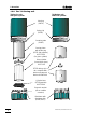
1. Overview 1.3.2 The 710 Dosing unit 710 Dosing unit with glass cylinder 710 Dosing unit with ETFE cylinder Housing (PBTP) Spring clip (PBTP) Centering tube (PVDF) Dosing piston with piston peg (PTFE and graphite), 6.1572.XXX (for glass cylinder) Glass cylinder (borosilicate glass) 6.1571.XX ETFE dosing cylinder, complete with piston and stopcock washer 6.1566.XXX Cylinder base (PTFE/graphite) 6.1573.
2.1 700 Dosino dosing drive 2 Setup 2.1 700 Dosino dosing drive Checks Please check immediately on receipt whether the shipment is complete and undamaged (compare with delivery note and list of accessories in section 4.4). If transport damage has occurred please refer to section 4.3 'Warranty'. Location The 700 Dosino is a robust instrument and can therefore be used under rough conditions in laboratories and factories. However, care must be taken that it is not exposed to a corrosive atmosphere.
2. Setup • Model 2.700.0020 with mini-DIN plug for connection to the following instruments: − 711 Liquino − 736, 751, 758, 784, 785 Titrinos − 756 KF–Coulometer The 6.2134.020 Adapter cable can be used for connecting Model 2.700.0010 (DB9-plug) to the instruments listed above. The location of the correct connection socket for the Dosino can be found in the ‘Instructions for Use’ of the corresponding control unit. Only connect the Dosino to a control instrument when this is switched off.
2.2 710 Dosing unit 2.2 710 Dosing unit Checks Please check immediately on receipt whether the shipment is complete and undamaged (compare with delivery note and list of accessories in section 4.5). If transport damage has occurred please refer to section 4.4 'Warranty'. 2.2.1 Mounting the dosing units Dosing units are available with different cylinder volumes from 2 to 50 mL (see accessory list, p. 45). Dosing units with glass cylinders (ordering no. 6.3031.
2. Setup If it is not possible to loosen a connection nipple by hand then you should use the 6.2739.000 Spanner supplied. Using the spanner to tighten up a nipple can damage the tubing connection. • Place the dosing unit on the reagent bottle and screw it down. Tighten the fixing ring (on the distributor) firmly. It is now possible to rotate the upper part of the housing in any direction you require. If the thread does not fit then you must use a threaded adapter, see p. 45. • Fill the 6.1619.
2.2 710 Dosing unit 2.2.2 Placing the drive on the 710 Dosing unit Check the positions of the centering tube and dosing piston of the dosing unit. housing rib on rib centering tube with recess • The plastic rib in the recess of the centering tube must be flush with the plastic rib on the dosing unit housing (rib on rib). • If necessary rotate the centering ring by hand until the rib on rib position is obtained. • Check the piston peg. It has to be flush with the upper edge of the dosing unit.
2. Setup Never use force when attaching the dosing drive! • Place the dosing drive (700 Dosino) on the 710 Dosing unit. The green line on the Dosino must coincide with the short white marking of the dosing unit; see accompanying diagram. The guide cams of the Dosino must be located in the openings provided for them. 70 0 Dosin o 10 ml 10 ml • Lock the drive, i.e. turn to the left (counterclockwise) until the stop is reached.
2.2 710 Dosing unit the gray upper edge of the dosing piston is just visible. • Release the piston pliers by pressing the white knob. • Then press the inverted dosing unit against a flat surface. The piston should now be flush with the upper edge of the dosing unit. 2.2.4 Removing the dosing drive from the 710 Dosing unit A dosing drive can only be removed from a dosing unit when the four-way valve is in Position 2 (filling port, exchange position).
2. Setup 2.
2.3 Dismantling the dosing units It is not normally necessary to dismantle the dosing unit when changing the reagent. Owing to the minimal exchange volume of only a few microliters and the 'EMPTY' and 'PREP' functions, which each control instrument possesses for the Dosino, the reagent in a dosing unit can be comfortably exchanged without much loss of reagent; please refer to chapter 3.2. Check the piston and cylinder of a dosing unit regularly (i. e. twice per year), see chapter 3.3.
2. Setup • Keep the white knob pressed down and rotate the dosing unit housing by approx. 1 cm to the right (counterclockwise). • Release the white knob and carefully lift the housing upwards. • Take care that the white spring clip inside the housing does not slip out of place. 2.3.2 Centering tube and glass cylinder piston peg • You can now see the centering tube, which rotates together with the internal cylinder on the distributor. • Remove the centering tube.
2.3 Dismantling the dosing units Use the piston pliers (6.1546.030) to pull the dosing piston out of the cylinder: • Press the white knob of the piston pliers. Two wire loops appear at the piston pliers tip. • Position the piston pliers so that these wire loops surround the piston peg. If you now release the knob carefully the piston pliers will snap shut and you can pull out the piston with the white knob (some force is required).
2. Setup 2.3.3 Centering tube and ETFE cylinder In a dosing unit with an ETFE cylinder the centering tube consists of two plastic parts. The dosing cylinder is integrated in the lower plastic part. • Open the housing as described in section 2.3.1. • Lift off the centering tube in one piece (i.e. both plastic parts) from the distributor. • The upper plastic part can simply be pulled off upwards. You can now see the plastic cylinder with the dosing piston.
2.4 Assembling the dosing units 2.4 Assembling the dosing units Several important points must be observed when assembling the dosing units. The dosing cylinder and piston, in particular its sealing lips, must not be damaged in the assembly process. • Place the black cylinder base with the stopcock washer facing downwards on a flat surface.
2. Setup • You can now attach the centering tube. The narrow and the wider web on the lower surface of the centering tube must fit into the corresponding recesses of the black cylinder base. The head of the piston push rod must fit into the opening on the top of the centering tube. • Press the centering tube firmly onto the cylinder base. • The centering tube with cylinder and cylinder base is now attached to the distributor. The centering tube must be correctly positioned in order to assemble the housing.
2.4 Assembling the dosing units • Lock the housing by turning it to the left (clockwise). Hold the distributor tightly. Do not use force! If all the parts fit together properly the housing will snap into place. • Now check that the piston and the centering tube are positioned correctly. The head of the piston must be flush with the upper edge of the housing. • Use the piston pliers to pull out the piston until the stop is reached and press the complete inverted dosing unit onto a flat surface.
2. Setup 2.4.1 ETFE cylinder • Insert the dosing piston into the cylinder as described in the previous section. • The centering tube for the plastic cylinder has a recess on its lower surface. recess double rib • Place the centering tube on the lower part of the cylinder so that the recess encloses the double rib on the outside of the lower part.
2.5 Dosino and dosing unit setup 2.5 Dosino and dosing unit setup Various stands and holding devices are available for Dosino burets: 2.5.1 Support mounting (6.2047.010) • Attach the support mounting to a support rod (10 mm dia.) • Place the dosing unit (without bottle) in the mounting from above. Screw the reagent bottle onto the dosing unit from below. • Version: free stand assembly 2.5.2 Double bottle holder (6.2055.100) • The double bottle holder can be adjusted in height.
2. Setup 2.5.3 727 Ti Stand (2.727.0XXX) • For titrations in particular we recommend the use of our 727 Ti Stand (with or without built-in magnetic stirrer). 2.5.4 Direct mounting on canisters • A Dosino with dosing unit can be directly mounted on a canister with a suitable adapter. Use 6.1618.050 Thread adapter.
3.1 Air bubbles are (almost) inevitable 3 The Dosino in practice 700 Dosinos can be connected to various control instruments. They are used as dosing drives which can be operated with different 710 Dosing units. The dosing unit forms the buret and is mounted directly on a reagent bottle or a canister. Changing a dosing unit (and therefore a reagent) is very easy. The drive is removed from one dosing unit with a single movement and attached to the next one.
3. The Dosino in practice dosing cylinder Simplified functional diagram • The dosing cylinder with the stopcock washer in the cylinder base is coupled to the centering tube. • The centering tube is loosely seated on a distributor fitted with four different channels. These channels lead to the different ports. 4-way valve Port 4 Port 1 4 1 • The dosing drive with its carrier rotates the centering tube and therefore the stopcock washer. This results in movement to a particular valve setting.
3.1 Air bubbles are (almost) inevitable The standard assignment listed below applies to the following Metrohm instruments; it cannot be altered: • • • • 726 / 796 Titroprocessor 736, 751 and 758 Titrino models 746 VA Trace Analyzer 756 KF-Coulometer The standard occupancy of the Dosino ports: Port 1 Dosing outlet; M6 threaded connection on the left-hand side of the housing. The liquid is ejected via dosing or titrating tip. Port 2 Filling inlet; M6 threaded connection on the bottom of the dosing unit.
3. The Dosino in practice 3.1 Air bubbles are (almost) inevitable As a result of leaky tubing connections or the release of dissolved air from the liquid to be dosed it is possible that air bubbles could collect in the dosing cylinder. Always check the tubing ends for damage before you attach the tubings. Please ensure that tubing connections are always tight. Always tighten up the screw nipples firmly by hand and take care that you do not damage the tubing ends when doing this.
3.2 Reagent exchange zero position The maximum position of the piston is (0 impulses) never exceeded in dosing processes. The remaining dead volume is therefore always larger than any air bubble which may remain after the 'PREP' function max. position has been carried out. This means that it cannot escape into the tubing system (10'000 imand affect the precision of the dosing pulse) process. The air bubble remains in the dosing cylinder. PREP position air bubble 3.
3. The Dosino in practice 3.3 Cleaning and maintenance Unlike the dosing units the dosing drive requires no special maintenance. You should ensure that it is not exposed to excessive dirt or corrosive influences. If aggressive reagents are dosed with Dosino burets then, when the dosing unit is not in use, it should be rinsed with an inert solvent ('PREP' function) and then emptied ('EMPTY' function). The dosing drive should be removed during longer periods (more than one week) of non-use .
3.3 Cleaning and maintenance 3.3.2 Cleaning the stopcock washer and distributor disk The stopcock washer and distributor disk must be checked regularly. Blockages of the disk opening or the outlet ports must be avoided at all costs. Dismantle the dosing unit completely. The black stopcock washer sits on the cylinder base and can be removed with a pair of forceps or a bent paper clip.
3. The Dosino in practice Assembling the stopcock washer and distributor disk • Insert the stopcock washer and press it down. The central hole of the disk must point towards the cylinder base. • Use a plastic pipet tip to extend the opening of the cylinder outlet on the bottom of the cylinder base. If the distributor disk was removed it can be reassembled as follows: • Use a plastic pipetting tip to extend the opening of the distributor. • Lightly grease the inner surfaces of the distributor disk with 6.
3.4 Troubleshooting / Problems 3.4 Troubleshooting / Problems 3.4.1 Dosino buret Dosing drive cannot be mounted on the dosing unit. Possible causes: • The carrier of the drive is in the wrong position. ⇒ Switch the control instrument off and then on again. If the carrier does not automatically rotate to the starting position switch it off again and rotate the carrier manually to the correct position. Pay attention to the marking ribs: rib on rib. See page 9. • The centering tube is wrongly positioned.
3. The Dosino in practice ⇒ Place the dosing unit with attached drive vertically on the distributor, marking rib on marking rib, and turn the dosing unit to the left until you can clearly hear the spring clip snap into position. You should now be able to remove the drive from the dosing unit. ⇒ You can also directly dismantle the dosing unit by placing the dosing buret without the distributor vertically on a flat surface and removing the drive.
3.4 Troubleshooting / Problems The whole system is blocked. Possible cause: • The Dosino or control instrument is in an exceptional faulty condition. ⇒ Check cable connections. ⇒ Switch control instrument off and on again. ⇒ Remove dosing drive from dosing unit. With the instrument switched on check whether the drive carrier can be rotated. – If yes then the dosing drive is faulty. – If no then dismantle the dosing unit. Clean the black stopcock washer in the cylinder base, see page 29. 3.4.
3. The Dosino in practice Dosing unit leaks from distributor Possible cause: • Leaky distributor disk. ⇒ Clean the stopcock washer and distributor disk, see page 29. Liquid above the piston Possible cause: • Worn or faulty piston and/or cylinder. ⇒ Replace dosing piston and cylinder, see page 13. Liquid drips into the bottle Possible cause: • Air in the cylinder. ⇒ Check the tubing ends, in particular that of the aspiration tubing. ⇒ Tighten all tubing connections manually.
3.4 Troubleshooting / Problems Housing cannot be closed Possible cause: • Spring clip inserted wrongly. ⇒ Remove housing and position spring clip correctly. Dosing cylinder does not fit in centering tube. Possible cause: • Dosing cylinder jammed or tilted on cylinder base. ⇒ Dismantle cylinder and use tool to reassemble correctly. Drying tube jammed.
3. The Dosino in practice Tubing not completely filled during PREP. Possible cause: • Incorrect parameters have been defined for the dosing unit. ⇒ Correct the tubing lengths and diameters; please refer to the ‘Instructions for Use’ of the control instrument. Tubing not completely emptied during EMPTY. Possible cause: • Incorrect parameters have been defined for the dosing unit. ⇒ Correct the tubing lengths and diameters; please refer to the ‘Instructions for Use’ of the control instrument.
4. Appendix 4 Appendix 4.1 Validation / GLP Among other things, GLP (Good Laboratory Practice) requires the regular checking of the precision and correctness of analytical instruments by means of SOPs (Standard Operating Procedure).
4.2 Dosing accuracy according to ISO 8655-3 4.2 Dosing accuracy according to ISO 8655-3 Metrohm Ltd. guarantees the following limits (according to ISO 8655-3, draft) for Dosino burets with glass cylinders: Max. permissible systematic error es Nominal cylinder volume in mL 2 5 10 20 50 Maximum permissible systematic errors es a) rel. ± 0,3 % ± 0,3 % ± 0,2 % ± 0,2 % ± 0,2 % abs.
4. Appendix ∑ (Vi − V ) 2 s= n −1 s : repeatability standard deviation Vi: distributed volume n : number of distribution Please note • The above-mentioned limits are related to water at 20 °C and are valid for dosing units with glass cylinders only. • The nominal volume of the dosing cylinders are printed on the housing of the dosing units. • The above-mentioned limits are valid for the useful volume range of 10 % to 100 % of the nominal volume.
4.3 Technical data 4.3 Technical data Dimensions (Dosino with dosing unit) Height: greatest diameter: Weight approx.
4. Appendix Safety specification Constructed and tested according to IEC 1010, class 3 The ‘Instructions for Use’ contains information and warnings which must be observed by the operator in order to ensure safe operation of the instrument. Electromagnetic compatibility (EMC) Emission This instrument meets the requirements of the standards EN 50081-1 01.92, EN 55011 (class B), EN 55022 (class B).
4.4 Warranty and Conformity 4.4 Warranty and Conformity 4.4.1 Warranty The warranty on our products is limited to defects that are traceable to material, construction or manufacturing error which occur within 12 months from the day of delivery. In this case, the defects will be rectified in our workshops free of charge. Transport costs are to be paid by the customer. For day and night operation, the warranty is limited to 6 months.
4. Appendix 4.4.2 EU Declaration of Conformity The Metrohm Ltd. company, Herisau, Switzerland hereby certifies, that the instrument: 700 Dosino meets the requirements of EU Directives 89/336/EEC and 73/23/EEC.
4.4 Warranty and Conformity 4.4.3 Declaration of Conformity The 700 Dosino was developed and manufactured in accordance with the requirements demanded by the ISO 9001 quality system regarding the design, manufacture and servicing of Metrohm instruments. Name of commodity: 700 Dosino Manufacturer: Metrohm Ltd.
4. Appendix 4.5 Accessories 700 Dosino 2.700.0010 Dosing drive with cable (DB9, 1 m), includes the following accessories: Piston pliers Instructions for use 6.1546.030 8.700.1023 700 Dosino 2.700.0020 Dosing drive with cable (8 pin Mini-Din plug, 1 m), includes the folowing accessories: Piston pliers Instructions for use 6.1546.030 8.700.1023 Options Accessories to separate order and on payment of extra charge: Adapters/Interfaces Adapter cable for 2.700.0010 Dosino 6.2134.
4.5 Accessories Accessories for 710 Dosing unit, see above Dosing unit with glass cylinder, piston and stopcock washer (no further accessories) 2 mL volume 6.1570.120 5 mL volume 6.1570.150 10 mL volume 6.1570.210 20 mL volume 6.1570.220 50 mL volume 6.1570.250 Dosing unit with ETFE cylinder, piston and stopcock washer (no further accessories) 2 mL volume 6.1567.120 5 mL volume 6.1567.150 10 mL volume 6.1567.210 20 mL volume 6.1567.220 50 mL volume 6.1567.250 Ball stopper for buret tips 6.1446.
4. Appendix Buret tips Antidiffusion tip, M6 thread Buret tip, M6 thread Earthing for buret tip, M6 thread Storage tupe for buret tips Mountings Support mounting, for stand rod Ø 10 mm Base plate with stand rod Ø 10 mm Double bottle holder for 2x 1 L bottles Ti-Stand 727 with built-in magnetic stirrer without mains adapter with mains adapter 115 V/9 V DC, USA .. with mains adapter 230 V/9 V DC, Europe .. Ti-Stand 727 without stirrer without mains adapter with mains adapter 115 V/9 V DC, USA ..
5. Index 5 Index ...........................11 .............................11 6.2134.010 Adapter cable ...5 6.2134.020 Adapter cable ...6 727 Ti Stand ......................22 9-pin plug ............................5 Accessories .......................45 Accuracy ...........................38 Adapters ............................45 Adsorber tube .....................8 Aggressive media ...............7 Aggressive reagents .........28 Air bubbles ..................26; 33 Air inlet ............
5 Index Safety specification .......... 41 Sample changer ................. 2 Sample preparation ............ 2 Sample series ................... 26 Screw nipple ....................... 7 Sealing lips ................. 17; 28 Service personnel ............... 6 Setup ............................ 5; 21 Sleeves ............................. 21 Soda lime ........................... 8 SOP .................................. 37 Spare parts ....................... 47 Spring clip .............