CH-9101 Herisau/Switzerland E-Mail info@metrohm.com Internet www.metrohm.com 719 S Titrino Program version 5.719.0021 Instructions for Use 8.719.1103 03.
Table of contens Table of contents 1 Introduction ..........................................................................................................1 1.1 Instrument description........................................................................................... 1 1.2 Controls and parts ................................................................................................. 2 2 Manual operation.........................................................................................
Table of contents 4.2.3 Equipment required: .................................................................................. 107 4.2.4 Diagnosis steps ......................................................................................... 107 4.3 Initialise and test RAM....................................................................................... 116 4.4 Releasing a locked spindle with inserted Exchange Unit ................................. 117 5 Preparations .................................
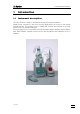
1.1 Instrument description 1 Introduction 1.1 Instrument description The 719 S Titrino is a titrator to perform fast and precise endpoint titrations. Ready-to-start methods for the most common applications are stored in the internal method memory. The operator is free to modify and overwrite this methods or to create and store his own titration sequences.
1.2 Controls and parts 1.
1.2 Controls and parts 1 Exchange Unit 2 Display 3 Setting of display contrast 4 Controls the dosing rate during manual dosing with and subsequent filling 5 Control keys and indicator lamps on the Titrino Key Key Key Indicator lamps: "Statistics" "Silo" 719 S Titrino Dosing key. Dispensing is performed as long as is being pressed. Used e.g. to prepare the Exchange Unit. The dispensing rate can be set with potentiometer (4). - Stops procedures, e.g.
1.
1.2 Controls and parts 6 RS232 interface for the connection of printer, balance or a computer 7 Remote lines (input/output) for the connection of the Remote Box, Sample Changers, robots etc. 8 Connection of electrodes and temperature sensor • 2 high-impedance measuring inputs for pH and U measurements (Ind I/ Ind II). They can either be used separately or for differential potentiometry, see page 124.
2.1. Keypad 2 Manual operation 2.1 Keypad CONFIG PARAM SMPL DATA STATISTICS Configuration. Parameters. Sample data. ON/OFF switching of statistics calculations of consecutive determination, see page 41. MEAS/HOLD ON/OFF switching of measurements between titrations and hold during titrations. SILO ON/OFF switching of silo memory for sample data, see page 51. CAL.DATA Calibration data, see page 49. C-FMLA Calculation values, see page 40. DEF Formulas, data output, see page 39ff.
2.2 Principle of data input 2.2 Principle of data input • If you press a key you will find the corresponding menu in the display. Example key : In the first line you see where you are: You pressed key and you are now in the menu "configuration". configuration >peripheral units • In our example you are in the menu "configuration" on the title ">peripheral units". By pressing you can move to the other titles of this menu.
2.3. Text input 2.3 Text input Example storing a method: • Press key , the group ">recall method" appears. user methods >recall method • Choose ">store method" by pressing and press . The name of the method which is currently in the working memory is displayed. >store method method name: • Delete this name with . <<> >store method method name: • Open the "text writing mode" with key <<>.
2.4 Tutorial 2.4 Tutorial This short operating course teaches you to work quick and efficient with the 719 S Titrino, by means of the most important applications. Set up your Titrino and connect the peripheral devices needed, see chapter 5. 2.4.1 Entering data, setting the dialog language We can thus make a start and first take a look at the fundamentals of the entry of data. We change the dialog language.
2.4. Tutorial Because this inquiry follows no colon ":" the value can't be selected by
2.4 Tutorial 2.4.2 Development of a method, titration of an acid Selection of the mode mode mode SET SET pH SET: • Press repeatedly until "SET" appears in the display. For a description of the SET mode see page 30ff. • Confirm "SET" with ******** pH 4 ×
2.4. Tutorial Minimum titration rate inside the control range. >SET1 min.rate 25.0µl/min 2 × • Quit the inquiry with . For the titration put a Exchange Unit with c(NaOH) = 0.1 mol/L on the Titrino and rinse the tubing and the buret Tipp with . Fill the buret again with . Plug a combined pH glass electrode into measuring input 1 (Ind I). Pipette 2 mL c(HCl) = 0.1 mol/L into your titration vessel, dilute with ca. 20 mL dist. water.
2.4 Tutorial Calculate the content of your hydrochloric acid in g/L: RS1=EP1*C01*C02/C00 End point*conc.(titrant)*molecular weight/sample size To correct a formula, delete it with . • Confirm the formula with . RS1=EP1*C01*C02/C00 >formula RS1 text RS1 • You may enter a text for the result output, see page 8. >formula RS1 decimal places 2 • Enter the desired number of decimal places for the result.
2.4. Tutorial Entry of the sample size 4 x smpl data smpl size • Press repeatedly until "sample size" appears in the display. • Enter 2. • Use
2.4 Tutorial Print reports 3 x • Press repeatedly until the display shows: • Press to move to the definition of reports. 3 x
2.4. Tutorial 2.4.3 Storage and loading of methods Now store the method you have just developed in the method memory. Storage of a method 2 × user methods >store method >store method method name: • Press repeatedly until the title ">store method" appears in the display. • Open the inquiry with . ******** • Enter an identifier, e.g. 1 or Acid. For text input see page 8. SET pH Acid The method now runs under the name "Acid". It is ready to titrate.
2.4 Tutorial 2.4.4 pH calibration For end-point titrations, however, where titration is performed to a fixed, specified pH value, a calibration should be performed. Selection of the calibration mode, CAL • Press repeatedly until "CAL" appears in the display and confirm the mode with . mode mode CAL CAL ******** pH(as) 7.00 slope 1.000 The instrument is ready for a 2-point calibration. The second display line shows the current calibration data for measuring input 1.
2.4. Tutorial 2.4.5 Statistics, acid capacity of drinking water Let us now determine the acid capacity of drinking water. For this, the SET (set endpoint titration) mode is used to titrate to pH = 4.3. Load the method "Acid", the one that you just have stored in the method memory, see page 16 . Set the end point pH = 4.3 and dynamics 3 as you did with your first example (key ). If you still feel unfamiliar with that, see page 11 again.
2.4 Tutorial If the previous titration has run to your satisfaction, you can start thinking about performing statistics calculations. Have you already added a new sample to the titration vessel? If you are no longer certain, you can find out immediately with . Rapid measurement between titrations Press . The pH value of your sample is displayed. You can stop the measurement with a second . Statistics calculations Now switch on the statistics calculations. Press .
2.4. Tutorial >statistics mean: n= 2 Mean value of 2 single determinations. • Enter "3" to include an additional determination. <3> 2 × • Quit the inquiry. Perform another titration. You can now decide which of the results is an "outlier". You can delete it from the statistics calculation. Deleting a result from the statistics calculation • Press until the display shows: 5 × parameters >statistics • Select with the inquiry of the result table "res.
2.5 Configuration, key 2.5 Configuration, key Key serves to enter device specific data. The set values apply to all modes. CONFIG peripheral units: Selection of printer, balance and the curve at the analog output. auxiliaries: e.g. setting of dialog language, date, time, etc. RS232 settings: RS parameters for the COM interface. common variables: Values of common variables. configuration >peripheral units The display texts of the Titrino are shown to the left.
2.5. Configuration, key General settings >auxiliaries dialog: english date 2001-03-13 time 08:13 Current date (YYYY-MM-DD) Format: Year-month-day, entry with leading zeros. Current time (HH-MM) Format: Hours-minutes, entry with leading zeros. Current run number for result output (0...9999) The sample number is set to 0 when the instrument is switched on and incremented on every determination. run number 0 auto start OFF Automatic starts of titrations. (1...
2.5 Configuration, key Values of the common variables >common variables C30 etc. 719 S Titrino 0.0 Common variables C30...C39 (0.. ± 999 999) The values of all common variables are displayed. For creating of common variables see page 43.
2.6. Selection of the mode, key 2.6 Selection of the mode, key MODE > – ; Press key until the desired mode is displayed and confirm with . Select the measured quantity pH, U, Ipol, Upol, (T) with
2.7 Parameters, key 2.7 Parameters, key The key is used for the entry of values that determine the modes. Values marked with "cond." are accessible during the conditioning in the SET mode. "**titr." means that these values can be changed during the titration. They influence the ongoing determination. Other values can only be changed in the inactive state. The display texts of the Titrino are shown to the left. The values are the default values. PARAM 2.7.
2.7. Parameters, key max.rate 10.0 ml/min Maximum dosing rate (0.01...150 mL/min, max.) sets "max.". This parameter determines primarily the addition rate outside the control range, see also page 31. The maximum rate depends on the Exchange Unit: Exchange Unit max. 5 mL 15 mL/min 10 mL 30 mL/min 20 mL 60 mL/min 50 mL 150 mL/min 25.0 µl/min Minimum dosing rate (0.01...999.
2.7 Parameters, key start V: Type of start volume (OFF, abs., rel.) "OFF": start volume switched off "abs.": absolute start volume in mL "rel.": relative start volume to sample size. OFF cond. start V 0.0 ml cond. 0 If "rel." is set: Factor for relative start volume (0...±999999). Calculated as: start V (in mL) = factor ∗ sample size max. ml/min Dosing rate for start volume (0.01...150 mL/min, max.) sets "max.". The maximum rate depends on the Exchange Unit: factor cond. dos.
2.7. Parameters, key Stop conditions for titration If this is not "normal", i.e. after reaching the EP. >stop conditions stop V: Type of stop volume (abs., rel., OFF) "abs.": absolute stop volume in mL. "rel.": relative stop volume to sample size. "OFF": stop volume switched off. Stop volume is not monitored. abs. **titr. stop V 99.99 ml **titr. factor 999999 **titr. Statistics calculation >statistics mean res.tab: delete 28 If "rel." is set: Factor for relative stop volume (0...
2.7 Parameters, key Preselections for the sequence >preselections conditioning: OFF display drift: ON cond. drift corr: OFF cond. drift value 0.0 µl/min Automatic conditioning of titration vessel. (ON, OFF) If conditioning is "on", between the titrations the titration solution is constantly maintained at the (1st) end point. When conditioning is performed, the volume drift can be displayed during the conditioning: Display of drift during conditioning (ON, OFF). Volume drift.
2.7. Parameters, key Titration sequence of SET (Activate pulse) (Start delay) (Preconditioning) ( (Activate pulse) (Start delay) After the start, the activate pulse is outputted. The start delay time is waited off. If conditioning is on, the sample solution is titrated until the (first) EP is reached. The display shows then drift OK or SET pH 2.3 µl/min conditioning The vessel is now conditioned. The titration can be started with . (Request ident.
2.7 Parameters, key Control parameters The control parameters can be set separately for each end point. Optimize your control parameters for routine analyses for samples with a rather low content. During the titration, reagent dosing occurs in 3 phases: U/mV 1. Initial dosing: Here the dosing rate increases constantly. The rate starts with "min.rate" and goes up to "max.rate". EP 2. Continuous dosing: Dosing is performed at the maximum rate "max.
2.7. Parameters, key Relation between the stop criteria "time" and "drift" The stop criterion "time", t(delay), means that the end point must be exceeded for a certain period of time. In other words, after the last dosed increment, time t is allowed to elapse before the titration is stopped. The size of this last increment depends on the volume of the Exchange Unit used. With a 20 mL Exchange Unit, the smallest possible increment is 2 µL.
2.7 Parameters, key If you have entered the endpoint and the control range (dynamics), the default values for the other control parameters should suffice for the first titration. If you encounter difficulties in optimizing your titration, the following table will be of use. How to proceed if ... Problem Dosing at the end too long and with too small increments. "Never ends!" Possible causes and corrective measures • Increase "min.rate". Perform an experiment with a much higher min.rate.
2.7. Parameters, key 2.7.2 Parameters for MEAS measuring parameters determine the measurement. statistics: Calculation of mean values and standard deviation, see also page 41. preselections: ON/OFF of various auxiliary functions such as automatic requests after the start and activate pulse. parameters >measuring parameters Measuring parameters >measuring parameters signal drift equilibr.
2.7 Parameters, key electrode test: temperature Electrode test (OFF, ON) Test for polarized electrodes. Performed on changeover from the inactive standby mode to a measurement. "OFF" means that the test is not performed. OFF Temperature (-170.0...500.0 °C) Temperature is measured at the start if a T sensor is connected. This parameter is used for temperature compensation in pH measurements. 25.0 °C Statistics calculation >statistics status: mean res.
2.7. Parameters, key 2.7.3 Parameters for CAL parameters >calibration parameters Calibration parameters >calibration parameters meas.input: cal.temp. 1 25.0 °C Measuring input (1, 2, diff.) Measuring input 1 or 2 or differential amplifier; Connection of electrodes, see page 124. Calibration temperature (-20.0 ... 120.0 °C) If a T sensor is connected, the temperature will be measured. The calibration temperature can also be input during the calibration sequence. pH value of first buffer (0...
2.7 Parameters, key sample changer cal: OFF Calibration with sample changer (ON, OFF) In calibrations with a sample changer, there are no hold points in the calibration sequence for inputs. Calibration temperature and pH values of the buffers (which are temperature dependent) must therefore be entered in advance. The inputs in key are valid. activate pulse: OFF Pulse output on the line "activate" (L6, pin 1) of the remote socket (all, first, OFF) See page 131.
2.7. Parameters, key Calibration sequence (Activate pulse) (Start delay) Measuring cal.temp. or entry Buffer 1 pH Measuring buffer 1 Buffer 2 pH Measuring buffer 2 etc. Data output 38 After the start, the activate pulse is output. The start delay time is waited off. Then, the calibration temperature is measured. It no T sensor is connected, you enter the temperature manually. Store the value with or continue with (T is not stored).
2.8 Result calculations 2.8 Result calculations Formula entry, key DEF 2 ( def >formula Key contains various inquiries for result calculations and data output. The data of this key are method specific and they are stored in the method memory together with the method. formula: Formulas for result calculations. The display texts of the Titrino are shown to the left. The values are the default values. >formula Input of formulas RS? Enter formula number (1...
2.8. Result calculations RS1 text RS1 Text for result output (up to 8 characters) Text input see page 8. RS1 decimal places 2 Number of decimal places for result (0...5) RS1 unit: % Selection of result unit (%, ppm, g/L, mg/mL, mol/L, mmol/L, g, mg, mL, mg/pc, s, mL/min, no unit or up to 6 characters). Enter next formula, e.g. for RS2. Meaning of the calculation variables CXX: C00 Sample size, see page 50. C01...C19 Method specific operands, see below.
2.9 Statistics calculation 2.9 Statistics calculation Mean values, absolute and relative standard deviations are calculated. DEF 2 The key is used to allocate results for statistics calculation. The entries are specific to the method and are stored in the method memory. ( mean: Assigns values for statistics calculations. def >mean The display texts of the Titrino are shown to the left. The values are the default values.
2.9. Statistics calculation How do you obtain statistics calculations? 1) Enter the allocations for the statistics calculation, see page 41. 2) Switch on the statistics calculations: Either with or set the status under , "> statistics" to "ON". The "Statistics" LED is on. Storing a method in the method memory, the status of the statistics calculation is retained. 3) Change the number of the individual values n under "mean n", if necessary. 4) Perform at least 2 titrations.
2.10 Common variables 2.10 Common variables Common variables are used for: • Determination of a titer with a method. This titer is stored permanently as C3X. The operand C3X can be used in various other methods like any other operand. • Determination of a blank values with a method . Using this blank value in various other methods. • Determination of a result with method. Reconciliation of this result in various other methods. You may view the values of the common variables with .
2.11. Data output 2.11 Data output Reports for the output at the end of a determination DEF 2 def >report ( With , the report sequence at the end of the determination is defined. The entries are specific to the method and are stored in the method memory. report: Definition of report blocks to be printed automatically at the end of the determination. The display texts of the Titrino are shown to the left. The values are the default values.
2.11 Data output Example of reports: 'fr 719 S Titrino 18200 719.0021 date 2002-03-13 time 17:34 3 pHc(init) 6.29 SET pH Acid EP1 0.0628 ml 4.26 m value 5.02 mmol/l mean(2) +/s s/% m value 5.04 0.028 mmol/l 0.56 device label Titr 1 sign: ============== Full result report Device label (if there is a designation, see page 22) and manual signature Additional possibilities for report outputs In addition to the reports which are printed at the end of the titration, various other reports can be put out.
2.11. Data output Result display without printer Results can also be viewed in the display. With
2.12 Method memory, keys 2.12 Method memory, keys USER METH 3 user methods >recall method ) Management of the internal method memory with key . Method identifications can be entered directly or selected with the
2.12. Method memory, keys The contents of the method memory can be printed with the key sequence Document your methods (e.g. parameter report, def. report and C-fmla report)! With a PC and the 6.6008.XXX Vesuv program, you should carry out a complete method backup from time to time.
2.13 Calibration data, key 2.13 Calibration data, key With , the current pH calibration data of all measuring inputs can be seen. Calibration data are entered here automatically on completion of a calibration. CAL.DATA 5 * input 1: Calibration data for measuring input 1. Identical for input 2 and diff. cal. data >input 1 The display texts of the Titrino are shown to the left. The values are the default values.
2.14. Current sample data, key 2.14 Current sample data, key The key can be used to enter the current sample data. The contents of this key change when the silo memory is switched on, see page 52. Instead of entering the current sample data with , you can request these data automatically after start of determinations. Configuration: , ">preselections". Current sample data can be entered live. For working with the silo memory see page 51. id#1...
2.15 Silo memory for sample data 2.15 Silo memory for sample data In the silo memory or pushup storage, sample data (method, identifications and smpl size) can be stored. This is useful, e.g. when you work with Sample Changers and other automatic sample addition systems. SILO 9 Press the key for working with the silo memory. The status LED "silo" is on when the silo memory is switched on. The silo memory works by the FIFO principle (First In, First Out).
2.15. Silo memory for sample data Key with the silo memory switched on Sample data can be entered into the silo memory with key . SMPL DATA edit silo lines: Entering sample data into the silo memory. delete silo lines: Deletes single silo lines. delete all silo lines: Deletes the whole silo memory. smpl data >edit silo lines The display texts of the Titrino are shown to the left. The values are the default values. Input for silo memory >edit silo lines silo line 1 Silo line (1.
2.15 Silo memory for sample data Delete all silo lines >delete all silo lines delete all: Confirmation (yes, no) When all silo lines are deleted, the silo is completely empty: The line numbering starts again with 1. no cycle lines: With "ON", worked off silo lines will be copied to the highest line of the silo memory (ON, OFF) Data cycling "on" is useful if you constantly have to process the same sample data.
3.1 General rules 3 Operation via RS232 Interface 3.1 General rules The Titrino has an extensive remote control facility that allows full control of the Titrino via the RS 232 interface, i.e. the Titrino can receive data from an external controller or send data to an external controller. CR and LF are used as terminators for the data transfer. The Titrino sends 2xCR and LF as termination of a data block, to differentiate between a data line which has CR and LF as terminators.
3.1. General rules 3.1.1 Call up of objects An excerpt from the object tree is represented below: 3rd node Language 2nd node 1st node Prog Aux RSSet Config Mode 0st node & Root Rules Example The root of the tree is designated by &. The branches (levels) of a tree are marked with a dot (.) when calling up an object. When calling up an object, it is sufficient to give only as many letters as necessary to uniquely assign the object.
3.1 General rules 3.1.2 Triggers Triggers initiate an action on the Titrino, for example, starting a process or sending data. Triggers are marked by the introductory symbol $. The following triggers are possible: $G Go $S $H $C $Q Stop Hold Continue Query $Q.P $Q.H Path Highest Index Name Detail-Info qUit $Q.N"i" $D $U Starts processes, for ex.
3.1. General rules 3.1.3 Status messages In order to have an efficient control by an external control device, it must also be possible to query status conditions; they provide information on the status of the Titrino. The trigger $D initiates output of the status. Status messages consist of the global status, the detailed status and eventual error messages, e.g. $S.Mode.SET;E26.
3.1 General rules Status conditions of the global $C: The status conditions of the global $C are identical with the ones of the global status $G. They appear when the process has been restarted actively from the status "Hold" ($C, key or automatically after elimination of an error). Status conditions of the global $R: Quick manual measurement from the initial status in mode XXXX. $R .Mode.XXXX.QuickMeas: Instrument in the SET mode, inactive.
3.1. General rules 3.1.4 Error messages Error messages are added to the status messages and separated from them by the sign ";". E20 E21 E22 E23 E26 E27 E28 E29 E30 E31 E32 E33 E34 60 Check exchange unit. Exit: Mount Exchange Unit (properly) or &m $S. Check electrode, short circuit. Exit: Rectify fault or &m $S. Check electrode, break. Exit: Rectify fault or &m $S. Division by zero. Exit: The error message disappears on next startup or on recalculation. Manual stop.
3.1 General rules E36 E37 E38 E39 E40 E41 E42 E43 E44 E45 719 S Titrino RS receive errors: Parity Exit: and ensure settings of appropriate parameters at both devices are the same. Stop Bit Exit: and ensure settings of appropriate parameters at both devices are the same. Overrun error. At least 1 character could not be read. Exit: The internal working-off buffer of the Titrino is full (>82 characters). Exit: RS send errors: DSR=OFF No proper handshake for more than 1 s.
3.1. General rules E120 E123 E128 E129 E130 E131 E132 E133 E134 E135 E136 E137 62 Overrange of the primary measured value (pH, U, Ipol, Upol or T with MEAS T). The secondary measured value (temperature) may be instable as well. Exit: Correct error or &m $S. Missing EP for calculation. Exit: The error message disappears on next startup or on recalculation. No new mean. Exit: The error message disappears on next startup or on recalculation. No new common variable, old value remains.
3.2 Remote control commands 3.2 Remote control commands 3.2.
3.2. Remote control commands &Mode Object Description & Root ├ Mode : ├ .QuickMeas ├ .Select ├ .SETQuantity ├ .MEASQuantity ├ .Name ├ .Parameter* Mode $G, $S, $H, $C Rapid meas. in basic mode $G, $S Mode selection SET, MEAS,CAL Measured quantity for SET pH, U, Ipol, Upol Measured quantity for MEAS pH, U, Ipol, Upol, T Name of current method read only/read+write Parameter of current mode, page 65ff │ ├ .Def │ ├ .Formulas │ │ ├ .1 │ │ │ ├ .Formula │ │ │ ├ .TextRS │ │ │ ├ .Decimal │ │ │ ├ .
3.2 Remote control commands *Parameter ├ .SET1 │ ├ .EP │ ├ .UnitEp │ ├ .Dyn │ ├ .UnitDyn │ ├ .MaxRate │ ├ .MinRate │ ├ .Stop │ │ ├ .Type │ │ ├ .Drift │ │ ├ .Time │ │ ├ .StopT ├ .SET2 ├ .TitrPara │ ├ .Direction │ ├ .XPause │ ├ .Start V │ │ ├ .Type │ │ ├ .V │ │ ├ .Factor │ │ ├ .Rate │ ├ .Pause │ ├ .ExtrT │ ├ .MeasInput │ ├ .Ipol │ ├ .Upol │ ├ .PolElectrTest │ │ ├ .Temp ├ .StopCond │ ├ .VStop │ │ ├ .Type │ │ ├ .V │ │ ├ .Factor │ │ ├ .FillRate ├ .Statistics │ ├ .Status │ ├ .MeanN │ ├ .ResTab │ │ ├ .
3.2. Remote control commands *Parameter ├ .Measuring │ ├ .SignalDrift │ ├ .UnitSigDrift │ ├ .EquTime │ ├ .MeasInput │ ├ .Ipol │ ├ .Upol │ ├ .PolElectrTest │ ├ .Temp │ ├ │ │ │ │ │ │ ├ │ │ │ │ .Statistics ├ .Status ├ .MeanN ├ .ResTab │ ├ .Select │ ├ .DelN │ .Presel ├ ├ ├ .IReq .SReq .ActPulse *Parameter .Calibration ├ .MeasInput ├ .CalTemp ├ .Buffer │ ├ .1 │ │ ├ .Value │ ├ .2 │ │ ├ .Value │ ├ : ├ .SignalDrift ├ .EquTime ├ .ElectrodeId ├ .SmplChanger ├ .
3.2 Remote control commands &UserMeth Object Description Input range Reference & Root : ├ UserMeth : ├ .FreeMemory ├ .Recall │ ├ .Name ├ .Store │ ├ .Name ├ .Delete │ ├ .Name ├ .DelAll ├ .List │ ├ .1 │ │ ├ .Name │ │ ├ .Mode │ │ ├ .Quantity │ │ ├ .Bytes │ │ ├ .Checksum ├ .
3.2. Remote control commands &Config Object Description Input range Reference & Root : ├ 68 Config ├ .PeriphUnit │ ├ .CharSet │ │ │ ├ .Balance │ │ │ ├ .Plot │ │ │ ├ .Aux │ ├ .Language │ │ │ │ │ ├ .Set │ │ ├ .Date │ │ ├ .Time │ ├ .RunNo │ ├ .AutoStart │ ├ .StartDelay │ ├ .DevName │ ├ .Prog │ ├ .RSSet │ ├ .Baud │ │ │ ├ .DataBit │ ├ .StopBit │ ├ .Parity │ ├ .Handsh │ │ │ ├ .ComVar │ ├ .
3.2 Remote control commands &SmplData Object Description Input range Reference & Root : ├ SmplData : ├ .Status ├ .OFFSilo │ ├ .Id1 │ ├ .Id2 │ ├ .Id3 │ ├ .ValSmpl │ ├ .UnitSmpl ├ .ONSilo │ ├ .Counter │ │ ├ .MaxLines │ │ ├ .FirstLine │ │ ├ .LastLine │ ├ .EditLine │ │ ├ .1 │ │ │ ├ .Method │ │ │ ├ .Id1 │ │ │ ├ .Id2 │ │ │ ├ .Id3 │ │ │ ├ .ValSmpl │ │ │ ├ .UnitSmpl │ │ ├ up to 99 lines │ ├ .DelLine │ │ ├ .LineNum │ ├ .DelAll │ ├ .
3.2. Remote control commands &Info Object Description Input range Reference & Root : ├ Info Current data : ├ .Report Transmission of formatted reports $G 3.2.2.58. │ ├ .Select Report type configuration, parameters, │ smpl data, statistics, silo, calib │ C-fmla, def, user method, full, │ short, calc, all, ff ditto │ ├ .CalibrationData pH calibration data $G 3.2.2.59. │ ├ .Inp1 For measuring input 1 │ │ ├ .pHas Asymmetry pH 0...7.00...±20.00 ditto │ │ ├ .Slope Slope of electrode 0...1.000...±9.
3.2 Remote control commands │ ├ up to 9 mean values │ ├ .ActualInfo Current data │ ├ .Inputs I/O Inputs │ │ ├ .Status Line status │ │ ├ .Change Change of line status │ │ ├ .Clear Clear change │ ├ .Outputs as for I/O Inputs │ │ ├ .Status Line status │ │ ├ .Change Change of line status │ │ ├ .Clear Clear change │ ├ .Assembly From Assembly │ │ ├ .CyclNo Cycle number │ │ ├ .Counter Assembly counter │ │ │ ├ .V Volume counter │ │ │ ├ .Clear Clears counter │ │ ├ .PistonPos Measured value │ │ ├ .
3.2. Remote control commands &Assembly Object Description Input range Reference & Root : ├ Assembly ├ . Bur │ ├ .Rates │ │ ├ .Forward │ │ │ ├ .Select │ │ │ ├ .Digital │ │ ├ .Reverse │ │ │ ├ .Select │ │ │ ├ .Digital │ ├ .Fill │ ├ .ModeDis │ │ ├ .Select │ │ ├ .V │ │ ├ .Time │ │ ├ .VStop │ │ ├ .AutoFill │ ├ .Meas │ ├ .Status │ ├ .MeasInput │ ├ .Ipol │ ├ .Upol │ ├ .Outputs │ ├ .AutoEOD │ ├ .SetLines │ │ ├ .L0 │ │ ├ up to L 3 │ ├ .
3.2 Remote control commands &Setup Object Description Input range Reference & Root : ├ Setup ├ .Keycode ├ .Tree │ ├ .Short │ ├ .ChangedOnly │ ├ .Trace │ ├ .Lock │ ├ .Keyboard │ ├ .Config │ ├ .Parameter │ ├ .SmplData │ ├ .UserMeth │ │ ├ .Recall │ │ ├ .Store │ │ ├ .Delete │ └ .Display │ ├ .Mode │ ├ .StartWait │ ├ .FinWait │ ├ .SendMeas │ ├ .SendStatus │ ├ .Interval │ ├ .Select │ ├ .Assembly │ │ ├ .CyclNo │ │ ├ .V │ │ ├ .Meas │ ├ .Titrator │ │ ├ .CyclNo │ │ ├ .V │ │ ├ .Meas │ │ ├ .dVdt │ │ ├ .
3.2. Remote control commands │ │ ├ .C │ │ ├ .O │ │ ├ .N │ │ ├ .Re │ │ ├ .Si │ │ ├ .EP │ │ ├ .RC │ ├ .I │ ├ .O │ ├ .PowerOn ├ .Initialise │ ├ .Select │ ├ .RamInit ├ .InstrNo ├ .Value 74 Continue after "hold" Conditioning OK Conditioning not OK Request after start Silo empty Entry in EP list Recalculation of results done Changing an I/O input Changing an I/O output ON, OFF ON, OFF ON, OFF ON, OFF ON, OFF ON, OFF ON, OFF ON, OFF ON, OFF RESET (power on) Set default values Selection of branch $G 3.2.2.87.
3.2 Remote control commands &Diagnose Object Description Input range Diagnose Output of adjustment parameters $G Reference & Root : ├ Diagnose ├ .Report 719 S Titrino 3.2.2.91.
3.2. Remote control commands 3.2.2 Description of the remote control commands 3.2.2.1. Mode $G, $S, $H, $C Start and stop ($G, $S) or hold of the current method (3.2.2.3) with $H and continue with $C. $G also serves to continue after inquiries of identifications and sample size after the start (see 3.2.2.25) as well as after inquiries of calibration temperature and pH values of buffers (see 3.2.2.31 and 3.2.2.32). 3.2.2.2. Mode.
3.2 Remote control commands Assignment of common variables. The values of the common variables are to be found in &Config.ComVar. They can be viewed and entered there, see 3.2.2.50. 3.2.2.7. Mode.Def.Report.Assign SET, MEAS, CAL: full, short, calc, param, calib, ff Definition of the report sequence, which is outputted automatically at the end of the determination. Entries of more than one block have to be separated with ";". 3.2.2.8. Mode.Def.Mean.1.Assign RS1, RSX, EPX, CXX Mode.Def.Mean.2.Assign etc.
3.2. Remote control commands 3.2.2.12. Mode.Parameter.SET1.Stop.Type drift, time Mode.Parameter.SET1.Stop.Drift 1...20...999 Mode.Parameter.SET1.Stop.Time 0...10...999, inf Mode.Parameter.SET1.Stop.StopT 0...99 999, OFF Parameters for SET: Type and size of the stop criterion of the titration. .Type: Type of stop criterion after stop drift or switch-off delay time. .Drift: Stop drift in µL/min. Applies when "drift" has been selected. .Time: Switch-off delay time in s. Applies when "time" has been selected.
3.2 Remote control commands Selection of the measuring input; valid with measured quantities pH and U. "diff." means differential amplifier, see page 124. With Ipol, the inquiries for the polarization current in µA (Ipol) and .PolElectrTest are valid. With Upol, the inquiry for the polarization voltage in mV (Upol) is valid. Entry in steps of 10 mV. Besides .PolElectrTest is valid.
3.2. Remote control commands delete all: Clear entire statistics table. The results can not be reactivated. .ResTab.DelN: Specification of the line number to be deleted. 3.2.2.23. Mode.Parameter.Presel.Cond Mode.Parameter.Presel.DriftDisp Parameters for SET: .Cond: Conditioning ON/OFF .DriftDisp: Drift display during conditioning ON/OFF. ON, OFF ON, OFF 3.2.2.24. Mode.Parameter.Presel.DCor.Type auto, man, OFF Mode.Parameter.Presel. DCor.Value 0.0, 99.9 Parameters for SET: .
3.2 Remote control commands Mode.Parameter.Measuring.PolElectrTest ON, OFF Parameters for MEAS: Selection of the measuring input; valid with measured quantities pH and U. "diff." means differential amplifier, see page 124. With Ipol, the inquiries for the polarization current in µA (Ipol) and .PolElectrTest are valid. With Upol the inquiry for the polarization voltage in mV (Upol) is valid. Entry in steps on 10 mV. Besides .PolElectrTest is valid.
3.2. Remote control commands Parameters for CAL: Calibration at Titrino. With "ON", there are no hold points in the calibration sequence for entries, the first buffer is measured directly. 3.2.2.36. Mode.Parameter.Calibration.ActPulse first, all, OFF Parameters for CAL: Output of a pulse on the I/O line "Activate", see page 131. 3.2.2.37. UserMeth.FreeMem read only Memory space, available for user methods or silo lines. $Q sends the number of free bytes, e.g. "4928". 3.2.2.38. UserMeth.Recall $G UserMeth.
3.2 Remote control commands Selection of the balance type and the signal at the analog output. 3.2.2.42. Config.Aux.Language Selection of the dialog language. english, deutsch, francais, espanol, italiano, portugese, svenska 3.2.2.43. Config.Aux.Set $G Config.Aux.Set.Date YYYY-MM-DD Config.Aux.Set.Time HH:MM Date and time. Input format of the date: Year-month-day, two-digit, enter leading zeros. Input format for the time: Hours:minutes, two-digit, enter leading zeros.
3.2. Remote control commands $G sets all RS settings. The changes are performed only if the instrument is inactive. After the setting of the interface parameters, wait at least 2 s to allow the components to equilibrate. Settings of the values for the data transmission via the RS interface: baud rate, data bit, stop bit, parity and type of handshake, see also page 95ff. The setting of the values must be initiated with $G immediately after entry of the values. 3.2.2.50. Config.ComVar.C30 with up to .
3.2 Remote control commands .UnitSmpl: If "no unit" is desired for the sample size, the blank string must be entered. 3.2.2.55. SmplData.ONSilo.DelLine $G SmplData.ONSilo.DelLine.LineNum 1...99, OFF Deletion of a silo line. The line # is deleted with &SmplData.ONSilo.DelLine $G. If a formerly deleted line is edited again, it becomes valid (function "undelete"). 3.2.2.56. SmplData.ONSilo.DelAll Deletes the entire silo memory. Must be triggered with $G. $G 3.2.2.57. SmplData.ONSilo.
3.2. Remote control commands Info.CalibrationData.Inp1.Date read only Info.CalibrationData.Inp1.ElectrodeId read only identical for .Inp2 and .Diff pH calibration data for measuring input 1. After the calibration, the data are entered automatically together with the date of the calibration and the electrode identification, see 3.2.2.34. Calibration data can be entered. They are accepted with &Info.CalibrationData $G. If calibration data are entered, the calibration date is deleted. 3.2.2.60. Info.
3.2 Remote control commands C44: (Last measured) temperature in °C. Used for the temperature compensation in pH measurements. C45: Start volume with SET in ml, "2.800". C46: Asymmetry pH of CAL, "6.89". C47: Relative electrode slope of CAL, "0.9950". 3.2.2.63. Info.StatisticsVal.ActN Info.Statistics.1.Mean Info.Statistics.1.Std Info.Statistics.1.RelStd etc. up to .9 The current values of the statistics calculation. $Q sends, e.g.
3.2. Remote control commands 3.2.2.66. Info.ActualInfo.Assembly.Counter.V read only Info.ActualInfo.Assembly.Counter.Clear $G $Q sends the volume. With the function &Info.Assembly.Counter.Clear $G, the volume counter is set to zero. 3.2.2.67. Info.ActualInfo.Assembly.Meas Info.ActualInfo.Assembly.PistonPos $Q sends the current measured value from the assembly. Piston position: 0 = initial position (filled) 10 000 = end position (empty) read only read only 3.2.2.68.
3.2 Remote control commands Info.ActualInfo.Display.L2 up to 24 ASCII characters Lines of the display. The display can be written to from the computer. Proceed as follows: Lock the display, see 3.2.2.80. $Q sends the contents of the corresponding display line. 3.2.2.71. Info.Assembly.CycleTime read only Info.Assembly.ExV read only Inquiries regarding basic variables of the assembly: Cycle time in s, volume of the active Exchange Unit in mL. 3.2.2.72. Assembly.Bur.Rates.Forward.
3.2. Remote control commands .Ipol: .Upol: Polarization current in µA. Polarization potential in mV, entry in steps of 10 mV. 3.2.2.76. Assembly.Outputs.AutoEOD ON, OFF Assembly.Outputs.SetLines $G Assembly.Outputs.SetLines.L0 active, inactive, pulse, OFF up to .L 3 Assembly.Outputs.ResetLines $G Setting the I/O output lines. .AutoEOD: The automatic output of the EOD (End of Determination) at the end of the determination can be switched off.
3.2 Remote control commands 3.2.2.80. Setup.Lock.Keyboard ON, OFF Setup.Lock.Config ON, OFF Setup.Lock.Parameter ON, OFF Setup.Lock.SmplData ON, OFF Setup.Lock.UserMeth.Recall ON, OFF Setup.Lock.UserMeth.Store ON, OFF Setup.Lock.UserMeth.Delete ON, OFF Setup.Lock.Display ON, OFF ON means disable the corresponding function: .Keyboard: Disable all keys of the Titrino .Config: Disable the key .Parameter: Disable the key .SmplData: Disable the key .UserMeth.
3.2. Remote control commands Selection of the values from Assembly for the output in the set time interval (see 3.2.2.82): .CyclNo: Cycle number of the potential measurement. Together with the cycle time (3.2.2.81), a time frame can be set up. The cycle number is set to 0 on switching on the instrument and it is always incremented as long as the instrument remains switched on. .V: Volume .Meas: Measured value associated to the cycle number. The unit "assembly" must be preset (see 3.2.2.83). 3.2.2.85.
3.2 Remote control commands ON means that the Titrino reports automatically the moment the corresponding change occurs. .Status: Global switch for all set AutoInfo. .P PowerOn: Simulation of power on (3.2.2.87). Not from mains. Messages from node .T, Titrator: .T.R Ready: Status 'Ready' has been reached. .T.G Go: Instrument has been started. .T.GC GoCommand: Instrument has received a go command. .T.S Stop: Status 'Stop' has been reached. .T.B Begin of sequence. .T.
3.2. Remote control commands Setup: All values under &Setup. All: Values of the entire tree (except silo and method memory). The action must be triggered with &Setup.Initalise $G. 3.2.2.89. Setup.RamInit $G Initializes instrument, see page 116. All parameters are set to their default value and error messages are cleared. The user and silo memories will be deleted. The user memory contains the default user methods from Metrohm. 3.2.2.90. Setup.InstrNo $G Setup.InstrNo.
3.3 Properties of the RS 232 Interface 3.3 Properties of the RS 232 Interface Data Transfer Protocol The Titrino is configured as DTE (Data Terminal Equipment). The RS 232 interface has the following technical specifications: • Data interface according to the RS 232C standard, adjustable transfer parameters, see page 10. • Max. line length: 512 characters • Control characters: CR (ASCII DEC 13) LF (ASCII DEC 10) XON (ASCII DEC 17) XOFF (ASCII DEC 19) • Cable length: max. approx.
3.3 Properties of the RS 232 Interface Titrino as Receiver : Titrino external device 60 characters max. 22 characters LF RxD Data output XOFF Time of 4 characters XON XOFF Data input TxD String is processed 400 µs Time Titrino as Sender : Titrino external device XOFF XON Data output RxD LF Data input TxD max. 4 characters Data output disabled Data output enabled Time Software-Handshake, SWline Handshake input ports on the Titrino (CTS, DSR, DCD) are not checked.
3.3 Properties of the RS 232 Interface Titrino as Receiver : Titrino external device LF Input Titrino disabled LF RxD Data output XON XOFF Data input TxD 400 µs String is processed Time Titrino as Sender: Titrino external device XOFF Inquiry LF XON Data output RxD 1st line Response LF LF Data input TxD Data output disabled Data output enabled Time Titrino transmission can be stopped by external instruments with XOFF.
3.3 Properties of the RS 232 Interface Titrino as Sender: Titrino external device RTS RTS CTS CTS LF TxD TxD Time The data flow can be interrupted by deactivating the CTS line. Hardware-Handshake, HWf All handshake inputs are checked at the Titrino, handshake outputs are set.
3.3 Properties of the RS 232 Interface 3.3.2 Pin Assignment RS232C Interface Transmitted Data (TxD). If no data are transmitted, the line is held in the “ON” condition. Data will only be sent when CTS and DSR are in the ”ON” condition and DCD is in the "OFF" condition. Received Data (RxD) Data are received only when DCD is "ON". Request to Send (RTS) ON condition: Titrino is ready to send data. Clear to Send (CTS) ON condition: Remote station is ready to receive data.
3.3 Properties of the RS 232 Interface Contact arrangement at plug (female) for RS 232C socket (male) 25 14 13 1 View of soldered side of plug Ordering numbers: K.210.9004 and K.210.0001 No liability whatsoever will be accepted for damage or injury caused by improper interconnection of instruments.
3.3 Properties of the RS 232 Interface 3.3.3 What can you do if the data transfer does not work? Problem Questions for remedial action No characters can be received on a connected printer. - Are the instruments switched on and cables plugged in correctly? Is the printer set to ”on-line”? Are baud rate, data bit and parity the same on both instruments? - Is the handshake set properly? If everything seems to be ok, try to print a report with the key sequence .
4.1 Error and special messages 4 Error messages, Troubleshooting Data transfer inoperative See measures on page 101. 4.1 Error and special messages XXX bytes missing check electrode check exchange unit check T-sensor division by zero manual stop missing EP no EP set no method no new com.var. no new mean not valid overrange same buffer 719 S Titrino XXX bytes missing. For the storage of a method or a silo line XXX bytes are missing. Remedy: .
4.1. Error and special messages silo empty silo full stop time reached stop V reached system error 3 wrong sample The silo memory is switched in but empty and a titration has been started. Corrective action: At least the first 1 silo line before starting the first titration. Exit: . The silo memory is full up. Corrective action: If you have filled less than 99 silo lines, you can create more space by deleting old methods no longer needed. 1 silo line needs 18...90 bytes. Exit: .
4.1 Error and special messages E43 E44 E45 719 S Titrino Exit: Is the receiver switched on and ready to receive? The transmission of the Titrino has been interrupted with XOFF for at least 3 s. Exit: . The RS interface parameters are no longer the same for both instruments. The receive buffer of the Titrino contains an incomplete string (missing LF). Transmission of the Titrino is thus blocked. Exit: Send LF or .
4.2. Diagnosis 4.2 Diagnosis 4.2.1 General The 719 S Titrino is a very precise and reliable instrument. Thanks to its rugged construction it is virtually impossible for external mechanical or electrical influences to have an adverse effect on its functions. Although the occasional fault in the instrument can not be excluded completely, it is certainly much more likely that malfunctions are caused by wrong operation or handling or through improper connections and operation with non-Metrohm instruments.
4.2. Diagnosis 4.2.3 Equipment required: − voltage calibrator, e.g. 1.773.0010 Metrohm pH Simulator − highly insulated interconnection cable 6.2108.060 − cable 3.496.5070 − exchange units, if possible with different cylinder volumes (or 3.496.0070 dummy exchange unit) − stop watch or watch with second hand − digital or analogue voltmeter (if need be, connect a calibrated recorder) − 2 connecting cables with 4 mm banana plugs − test plug 3.496.
4.2. Diagnosis 3 Keypad test • Press <1>. keys test • Press . keys test matrix code • If any key is now pressed (on the 6.2132.110 keypad or on the fron panel of the 719), the appropriate matrix code appears in the display. Fig. 2 Fig. 1 Front panel 719 Keypad 719 • Block 1 is quit by pressing the key twice. diagnose press key 0...9 4 Cylinder code, date, time • Put exchange unit or dummy on the Titrino and put the burette tip into a collecting receptacle. • Press <0>.
4.2. Diagnosis date/time cylinder code • Press . date XX-XX-XX XX:XX:XX code:D0 XX ml activated dosing unit mL-code • Check date and time. • Check whether the mL-code does correspond with the exchange unit placed or not. For the sake of completeness, different exchange units can be inserted to check their mL code. If desired, the exchange unit can be removed again. If no exchange unit is inserted display does not show the mL-code but „check exchange unit !“. • Press .
4.2. Diagnosis pot.meter dV/dt 10? • Turn knob ‘dV/dt’ to the right stop and press . Test sequence: a) In a first step, the frequency of the RC oscillator (analogue rate) is tested over a period of 1 second. b) In a second step, the frequency of the quartz oscillator (digital rate) is tested over a period of 1 second. c) If no error is found, after about 3 s it appears motor-timer test o.k. • Press . diagnose press key 0...9 7 Analogue input test • Press <7>. analog input test 1...
4.2. Diagnosis Input 2 XX mV • Carry out the same measurements as with Input 1. • Press . analog input test 1...5 • Short-circuit input ‘Ind I’ (e.g. with cable 3.496.5070). • Press <3>. Input 1-2 XX mV The differencial voltage between inputs ‘Ind I‘ and ‘Ind II’ is displayed. Example: 0 - (+)1500 mV = -1500 mV • Remove cables from the inputs ‘Ind I’ and ‘Ind II’. • Press . analog input test 1...5 7.
4.2. Diagnosis dummy resistor 14.3kΩ ? • Connect resistor switch-box (or suitable resistor 14.3 kΩ 0.1%) using 3.496.5070 cable to ‘Pol’ socket. Switch-box to 14.3 kΩ. • Press . Test sequence: 1. An asterisk flashes during the test. 2. In case of an error an error message appears. (If for example the switch-box is not connected, error 100 appears). 3. If no error is found, after about 15 s display shows polarizer test o.k. • Press . analog input test 1...5 • Press .
4.2. Diagnosis I/O-test-connector? • Insert the 3.496.8510 test plug in port B 'Remote'. (Do not switch off instrument!) • Press . Test sequence: 1. In case of an error an error message is displayed. If for example no test plug is connected, error message error 50 01HEX appears). 2. If no error is found, after about 1 s display shows extern input/output o.k. • Remove test plug. • Press . diagnose press key 0...9 9 RS 232 test A 3.496.
4.2. Diagnosis RS232 test-connector? • Insert the 3.496.8480 test plug in 'RS 232' port. • Press . Test sequence: 1. In case of an error an error message is displayed. If for example no test plug is connected, error message error 68 appears). 2. If no error is found, after about 5 s display shows RS232 test o.k. • Remove test plug. • Press . diagnose press key 0...9 10 Spindle drive and stopcock changeover • Press .
4.2. Diagnosis Spindle remains at maximum position. The transit time of the spindle is 20 s. • Measure spindle lifting (can be performed only if the 3.496.0070 Dummy Exchange Unit is inserted or the locking switch (in right hole) is carefully operated with a screwdriver after removal of the Exchange Unit). From the start point, the spindle travels 80 mm. Instead of the spindle height, the expelled volume can be measured (corresponds to max. vol. of Exchange Unit used).
4.3. Initialise and test RAM 4.3 Initialise and test RAM On the odd occasion large disturbing signals (e.g. mains spikes, lightning, etc.) can have an adverse effect on the processor functions and hence lead to a system crash. After such a crash the RAM area must be initialised. Although the basic instrument data remain stored, the RAM initialisation should be performed only when necessary since the stored user data (configuration, parameters, calculation variables, etc.) are cleared as a result.
4.4. Releasing a locked spindle with inserted Exchange Unit 4.4 Releasing a locked spindle with inserted Exchange Unit • The burette drive may very occasionally jam at the top or bottom end of the cylinder. If jamming occurs at the top or when the drive is out of function, the Exchange Unit can no longer removed. In this case, it is necessary to proceed as follows: 2 screws (M4 countersunk) 2 screws (M3 fillister head) knob edge of bench Fig.
5.1. Setting up and connecting the instruments 5 Preparations The mains cables supplied with the instrument are three-core and equipped with a plug with an earthing pin. If a different plug has to be fitted, the yellow/green lead must be connected to the protective earth. Each break in the earthing inside or outside the instrument can make it a hazard. When the instrument is opened or if parts of it are removed, certain components may be live if the instrument is connected to the mains.
5.1 Setting up and connecting the instruments 5.1.2 Connection of a printer Printer Seiko DPU-414 Custom DP40-S4N A variety of printers can be connected to the RS232 interface of the Titrino. If you connect a printer other than one of those mentioned below, ensure that the Epson mode is emulated or that it uses the international character set following the IBM Standard Table 437 and IBM-compatible graphics control characters.
5.1. Setting up and connecting the instruments 5.1.3 Connection of a balance The following balances can be connected to the RS232 output of the Titrino: Balance Cable Sartorius MP8, MC1 6.2125.070 Shimadzu BX, BW 6.2125.080 Settings on Ohaus Voyager, Explorer, Analytical Plus Titrino: Balance: balance delimiter SARTORIUS CR+LF from Ohaus: AS017-09 (Ohaus parts number)+ 6.2125.
5.1 Setting up and connecting the instruments The weight is transferred as a number with up to 6 digits, sign and decimal point. Units and control characters sent by the balance are not transmitted. With the aid of a special input unit supplied by the balance manufacturer, in addition to the weight identifications and methods can be inputted from the balance. For this, the address of the identifications and method, resp. must be preselected on the input unit.
5.1. Setting up and connecting the instruments 5.1.5 Connection of a recorder The recorder is connected to the analog output of the Titrino. 719 A B C D Recorder The signal at the analogue output can be preselected on the Titrino (key , ">peripheral units", "curve:"): Preselection at Titrino U Voltage dU/dt Measured value drift V dV/dt U(rel) Volume Volume drift Control deviation T 122 Meaning Temperature Resolution, Signal at analogue output pH = 0.00: − 700mV pH = 7.
5.1 Setting up and connecting the instruments 5.1.6 Connection of a computer 719 A C B D Cable 6.2125.060 (+6.2125.010) PC Preselections on the Titrino: RS232 settings: ......................................... depend on the control program of the computer Send to: ............................................................................................................................IBM Vesuv 3.0, PC program for data acquisition and method backup for up to 64 devices..............................
5.2. Connection of electrodes, preparing titration vessel 5.2 Connection of electrodes, preparing titration vessel Rear panel: Ref Ref Connection for separate reference electrode. Input is free when a combined electrode is used. Pol Connection of polarized electrodes. If measured quantities Ipol or Upol are selected, this measuring input is automatically active. Ind I Connection of pH, redox, ISE electrodes. Combined or separate electrodes. Select measuring input 1 or 2 in the Titrino.
5.2 Connection of electrodes, preparing titration vessel Practical tips • Glass electrodes should be preconditioned in the solvent used for ca. 1 hour. • If the potential jump after the first dispensing step is too large, a small start volume may help. • As an "auxiliary electrode", the 6.1808.030 burette tip with earthing may be used in some cases.
5.2. Connection of electrodes, preparing titration vessel Setting up the titration vessel The titration vessel is set up as shown below. During a titration, it is important to ensure that the solution in contact with the electrode is thoroughly mixed. This is achieved by • efficient stirring. But it should not be too fast, otherwise the stirrer vortex will suck in air bubbles and CO2 or O2 can disturb the titration.
6.1 Technical specifications 6 Appendix 6.1 Technical specifications Modes SET: Set End point Titration MEAS: Measurement CAL: pH calibration Measuring inputs 2 high-impedance measuring inputs for pH, redox and ISE electrodes. 1 reference input for a separate reference electrode. May also be used as a differential amplifier. 1 measuring input for polarized electrodes. 1 measuring input for temperature sensor Pt100 or Pt1000. Measuring range pH value (pX) Voltage Current Temperature 0...±20.
6.1. Technical specifications RS232 interface for printer, balance or computer connection: completely controllable from external control unit Remote input/output lines for Sample Changer, robot connection, etc. Analog output Output signal Signal at analogoutput Ambient temperature Nom. operation range Storage Transport Safety specifications Mains connection Voltage Frequency Power consumption Fuse -2000 ...
6.2 Pin assignment of the "Remote" socket 6.
6.2. Pin assignment of the "Remote" socket Outputs pin 17 (Output 3) End of determination EOD pin 3 (Output 4) To be set via RS232 control pin 16 (Output 5) Error, active with errors pin 1 (Output 6) Activate pulse, see page 131. pin 2 (Output 7) Pulses for recorder (tp=150 µs) 10 000 per buret cylinder For all outputs: VCE0 = 40 V IC = 20 mA tPulse > 100 ms Functions see page 131. Voltage +5 V pin 15 I ≤ 75 mA 0V pin 14 0 V: active 5 V: inactive pin 25 Ordering numbers for plug: K.210.
6.2 Pin assignment of the "Remote" socket 6.2.
6.2. Pin assignment of the "Remote" socket 6.2.
6.3 User methods 6.3 User methods 6.3.1 General The methods are stored in the user memory ready for use. They can be loaded, modified and overwritten. If the result should have another unit, you need to adjust the calculation constants using the key . Stop volumes or other stop conditions should be entered depending on sample. If a printer is connected, the methods should be completed with report instructions (key ). The following methods are available: 'um 719 S Titrino 18200 719.
6.3. User methods 6.3.2 "Tit.HCl" Titer determination of HCl using TRIS. 'pa 719 S Titrino 18200 719.0021 date 2002-03-13 time 12:24 0 SET pH Tit.HCl parameters >SET1 EP at pH 5.10 dynamics 3 max.rate 5 ml/min min.rate 0.5 µl/min stop crit: drift stop drift 20 µl/min >SET2 EP at pH OFF >titration parameters titr.direction: auto pause 1 0 s start V: rel. factor 70 dos.rate max. ml/min pause 2 5 s extr.time 0 s meas.input: 1 temperature 25.0 °C >stop conditions stop V: abs. stop V 99.99 ml filling rate max.
6.3 User methods 6.3.3 "Tit.NaOH" Titer determination of NaOH using PHP. 'pa 719 S Titrino 18200 719.0021 date 2002-03-13 time 12:44 0 SET pH Tit.NaOH parameters >SET1 EP at pH 8.65 dynamics 3 max.rate 5 ml/min min.rate 0.5 µl/min stop crit: drift stop drift 20 µl/min >SET2 EP at pH OFF >titration parameters titr.direction: auto pause 1 0 s start V: rel. factor 35 dos.rate max. ml/min pause 2 5 s extr.time 0 s meas.input: 1 temperature 25.0 °C >stop conditions stop V: abs. stop V 99.99 ml filling rate max.
6.3. User methods 6.3.4 "p+m_Val" 136 'pa 719 S Titrino 18200 719.0021 date 2002-03-13 time 12:49 0 SET pH p+m_Val parameters >SET1 EP at pH 8.20 dynamics 2 max.rate 5 ml/min min.rate 5 µl/min stop crit: drift stop drift 20 µl/min >SET2 EP at pH 4.30 dynamics 3 max.rate 5 ml/min min.rate 5 µl/min stop crit: drift stop drift 20 µl/min >titration parameters titr.direction: auto pause 1 0 s start V: OFF pause 2 0 s extr.time 0 s meas.input: 1 temperature 25.0 °C >stop conditions stop V: abs. stop V 99.
6.3 User methods 6.3.5 "Br_No" 'pa 719 S Titrino 18200 719.0021 date 2002-03-13 time 13:05 0 SET Ipol Br_No. parameters >SET1 EP at U 500 mV dynamics 500 mV max.rate 10.0 ml/min min.rate 25.0 µl/min stop crit: drift stop drift 20 µl/min >SET2 EP at U OFF mV >titration parameters titr.direction: pause 1 0 s start V: OFF pause 2 0 s extr.time 0 s I(pol) 10 µA electrode test: OFF temperature 25.0 °C >stop conditions stop V: abs. stop V 99.99 ml filling rate max. ml/min >statistics status: ON mean n= 3 res.
6.4. Validation / GLP 6.4 Validation / GLP GLP (Good Laboratory Practice) requires the periodic validation of the analytical instruments. The reproducibility and accuracy of the instruments are checked according to standard operating procedures. Guidelines for the testing regulations (SOP, Standard Operating Procedure) are given in the following Metrohm Application Bulletin: No. 252: Validation of Metrohm Titrators (potentiometric) according to GLP/ISO 9001.
6.5 Warranty and conformity 6.5 Warranty and conformity 6.5.1 Warranty The warranty regarding our products is limited to rectification free of charge in our workshops of defects that can be proved to be due to material, design or manufacturing faults which appear within 12 months from the day of delivery. Transport costs are chargeable to the purchaser. For day and night operation, the warranty is valid for 6 months.
6.5. Warranty and conformity 6.5.2 EU Declaration of conformity EU Declaration of Conformity The METROHM AG company, Herisau, Switzerland hereby certifies, that the instrument: 719 S Titrino meets the requirements of EC Directives 89/336/EEC and 73/23/EEC.
6.5 Warranty and conformity 6.5.3 Certificate of Conformity and System Validation Certificate of Conformity and System Validation This is to certify the conformity to the standard specifications for electrical appliances and accessories, as well as to the standard specifications for security and to system validation issued by the manufacturing company. Name of commodity: 719 S Titrino System software: Stored in ROMs Name of manufacturer: Metrohm Ltd.
6.6. Scope of delivery and ordering designations 6.6 Scope of delivery and ordering designations 719 S Titrino ......................................................................................2.719.0020 inclusive the following accessories: 1 Titrino................................................................................................................. 1.719.0020 1 Keypad for 719 S Titrino.................................................................................... 6.2132.
6.6 Scope of delivery and ordering designations Titration equipment Titration vessel, volumes 1... 50 mL .................................................................................................. 6.1415.110 5... 70 mL .................................................................................................. 6.1415.150 10... 90 mL .................................................................................................. 6.1415.210 20... 90 mL ..........................................
6.6. Scope of delivery and ordering designations Balances Cable Sartorius – balances MP8, MC1 (9/25 pins) .............................................. 6.2125.070 Cable Shimadzu – balances BX, BW ................................................................... 6.2125.080 Ohaus Voyager, Explorer, Analytical Plus ................................................. cable from Ohaus Mettler AB, AG balances (interface LC-RS25) ......................................... cable with balance Mettler AT balance ....
Index Index Keys are marked with < >, display texts are in bold characters and pages concerning the green part are printed in Italic. A Accessories ...........................................142ff activate pulse: ............................29, 35, 36 Analogue output connection of a recorder.....................122 resolution.............................................122 test.......................................................109 auto start .................................................
Index electrode test: ................................. 26, 34 End volume ............................................... 40 EP titration................................................. 25ff EP at pH .................................................... 25 equilibr.time ..................................... 34, 36 Error messages............................... 60, 103ff Examples....................................... 11ff, 133ff Exchange unit ..................................... 3, 142 extr.time ...........
Index CAL........................................................36 MEAS.....................................................34 SET ........................................................25 parity: ......................................................22 pause 1 ......................................................26 pause 2 ......................................................26 peripheral units ......................................21 Perturbation ...........................................
Index stop V ........................................................ 28 system error 3 ....................................... 104 26 Tree ..........................................................63ff Troubleshooting.................................... 103ff Tutorial ...................................................... 9ff T U t(delay) .................................................... 25 U(pol) ................................................. 26, 34 Unit result ................................