CH-9101 Herisau/Switzerland Phone +41 71 353 85 85 Fax +41 71 353 89 01 EMail sales@metrohm.ch http://www.metrohm.ch 726 Titroprocessor Program version 5.726.0012 Instructions for use 8.726.
Table of content 1 Introduction 1 1.1 Range of applications _____________________________ 1 1.2 Application possibilities ___________________________ 1 1.3 Instrument description ____________________________ 3 1.3.1 Model versions ............................................................................ 3 1.3.2 Front view .................................................................................... 3 1.3.3 Rear view................................................................................
Table of content 3 Configuration 33 3.1 Basic settings____________________________________ 33 3.2 Configuration of sample changers ________________ 37 3.2.1 Sample racks .............................................................................38 3.2.2 Special beakers .........................................................................41 3.2.3 Basic configuration of 717 Sample changer .............................42 3.3 Interface configuration ___________________________ 43 3.3.
Table of content 6 Sample data and sample silo 91 6.1 Sample data entry________________________________ 91 6.1.1 Direct data transfer from balances ............................................ 91 6.1.2 Bar-code reader ........................................................................ 92 6.2 Sample silo ______________________________________ 92 6.2.1 Sample silo configuration.......................................................... 95 6.2.2 Automatic data input and output ..........................
Table of content 8 Command Reference 127 8.1 Titration modes _________________________________127 8.2 DET _____________________________________________128 8.2.1 Specific parameters for DET modes [ * Param ] ....................130 8.2.2 User adjustments .....................................................................136 8.2.3 EP recognition..........................................................................138 8.2.4 Curve display ................................................................
Table of content 10 Curves and re-evaluation 218 10.1 Single curves __________________________________218 10.2 Overlapping curves ____________________________221 10.3 Curve presentation_____________________________222 10.4 Re-evaluation __________________________________224 11 File manager 225 11.1 File list ________________________________________225 11.2 File operations _________________________________226 11.3 Format data card ______________________________227 11.
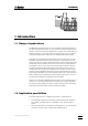
1. Introduction 1 Introduction 1.1 Range of applications The Metrohm 726 Titroprocessor is a very versatile analytical instrument. It has been designed exclusively for use in production plant and laboratories where it covers a wide range of applications. Together with the Metrohm 717 Sample changer it is very useful when processing large series of samples covering the whole field of titrations or for different measurement tasks.
1.2 Application possibilities • Up to twelve Dosinos or Dosimats can be addressed for titrating or dosing tasks. • The 726 Titroprocessor has a connection for a bar-code reader for entering sample-specific data available in bar-code format.
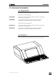
1. Introduction 1.3 Instrument description 1.3.1 Model versions The 726 Titroprocessor is available in four versions. Versions with 1 measuring group: 2.726.0010 with complete accessories, without built-in printer, but with parallel interface for an external printer 2.726.0020 as 2.726.0010, but with built-in space-saving thermal printer (DIN A4), without additional parallel interface for a printer Versions with 2 measuring groups: 2.726.
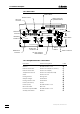
1.3 Instrument description 1.3.3 Rear view Serial number Bar-code connector Remote socket Printer connector (parallel interface) BarCode Stirrer Int A connector Remote D 1 C Ind A2 Ind A1 Ref Pol F 2 Pt100/1000 C Ind B2 Ind B1 Ref Sensors A Measuring interface A Type 1.726.0010 Printer E Pol Fuse holder Pt100/1000 Sensors B Dos. A1 Dos. A3 2A(TH) 1 0 Dosing Units B External Bus Dos. A2 A Dos.
1. Introduction 1.3.5 Measuring interfaces / Measuring inputs The 726 Titroprocessor models 2.726.0110 and 2.726.0120 are equipped with 2 measuring interfaces (Sensors A and Sensors B). The diagram below shows where the sensors are to be connected to measuring interface A, which is found on all 726 Titroprocessor models.
1.3 Instrument description SRAM cards can be read and written on. Capacity: 128 KB (Order no. 6.2245.010) to 2 MB. Card battery Data cards are battery-buffered storage media. The battery must be changed periodically in order to avoid data loss. Make a note of the expiry date of the battery which is given on the leaflet accompanying the card. Important: The expiry date of the battery refers to a storage temperature of 25°C. At higher storage temperatures the working life of the battery is shorter.
1. Introduction 1.4 The keyboard STOP QUIT ON FORM PRINT SKIP LINE PRINT FEED SCREEN F1 F2 F3 F4 F5 F6 F7 F8 F9 HELP HOLD DELAY NEXT CONT STOP INS HOME PG UP DEL END PG DN START OFF GLP ! @ # $ 1 2 3 4 Q W 5 E R ^ & * ( ) 6 7 8 9 0 Y T U I + - O = P µ ° [ ] : CAPS LOCK A S Z D F X C G V H B J N K M L " < > ? , .
1.4 The keyboard 1.4.3 Action keys SKIP HOLD CONT DELAY STOP NEXT START The action key have an immediate effect on the course of a method. The key starts a method; the key ends it. The key can be used to interrupt a method or to resume it. If the key is pressed at the same time as an action key the processing of a series of samples can be controlled directly (with Autostart 'on').
1. Introduction INS HOME PG UP DEL END PG DN moves the field cursor in the sample silo or method editor up by one page. moves the field cursor in the sample silo or method editor down by one page. moves the cursor up by one line. moves the cursor down by one line. moves the cursor one field (in navigation mode) or one character (in editing mode) to the left.
1.4 The keyboard Entry of special characters In the editing mode any character contained in the ASCII character set can be entered. This is carried out by first entering the character ^ and then the 3-place number of the required character. This is then displayed immediately.
1. Introduction 1.5 Dialog 1.5.1 Dialog overview The user dialog of the 726 Titroprocessor consists of 10 main pages, which contain hierarchically structured subwindows. Main page Configuration page Subwindow Subwindow Load method Files page Subwindow Method page Subwindow Subwindow Curves page subwindow Results page Samples page Subwindow Devices page Subwindow Variables page Subwindow The main page of the 726 Titroprocessor is the entry to the user dialog.
1.5 Dialog 1.5.3 The trace window During the course of a method the display windows of the application note changes to a trace window, showing the state of the currently executed commands. The display format depends on the current command or mode. command with line number Line time Measuring quantity ÚÄÄÄÄÄÄÄÄÄÄÄÄÄÄÄÄÄ Trace ÄÄÄÄÄÄÄÄÄÄÄÄÄÄÄÄÄÄÄ¿ ³ 0s 1. DET_PH* Titr.
1. Introduction The shortcut keys of the rightmost key column on the keyboard allow direct access to some important dialog windows or features. 1.5.5 Field cursor To navigate on a page or in a dialog window you can use the cursor keys <ç>, <è>, <é> or <ê>. The position of the so called field cursor is indicated by the black field background of the edit field the cursor is pointing to. To navigate right or left within a line you can use the key or the key combination, respectively.
1.6 How to edit Example: To change the destination memory of data files for use with the auto save function, set the field cursor to the destination field on the Titroprocessor's main page. Type 'd' then and press the key. The entry of the destination field will be set automatically to 'Data card'. This is the quickest way to modify entry fields . 1.6.1 Navigation in edit mode In edit mode the cursor keys <ç ç> and <è è> allow the navigation within an entry field.
2. Installation 2 Installation 2.1 Instrument setup Packaging The 726 Titroprocessor is supplied together with the specially packed accessories in packaging containing shock-absorbing foam which provides excellent protection. Please store this special packaging as it guarantees damage-free transport of the instrument. Checks Please check immediately on receipt whether the shipment is complete and undamaged (compare with delivery note and list of accessories on page 290).
2.3 Mains connection Earth socket Mains voltage selector S2 Mains connection WARNING - Fire Hazard For continued protection replace only with the same type and rating of fuse Mains switch Fuse holder S1 115V 230V 2A(TH) 230V 115V: 100V...120V 10% 230V: 220V...240V 10% Rear view 50-60Hz 160VA 2.3 Mains connection 2.3.1 Fuses Two fuses S1 and S2 are built into the 726 Titroprocessor as standard; both are type 2 ATH (2 A, slow-blow, with high switching capacity, Metrohm order no. U.600.0107).
2. Installation 2.3.2 Mains cable and mains connection The instrument is supplied with one of three types of cable: • 6.2122.020 with plug SEV 12 (Switzerland, …) • 6.2122.040 with plug CEE(7), VII (Germany, …) • 6.2133.070 with plug NEMA 5-15 (USA, …) which has three leads and is fitted with a plug with an earthing pin. If a different plug has to be fitted then the yellow/green lead (IEC standard) must be connected to the earth (protection class 1).
2.4 Data card handling (PC cards) 2.4 Data card handling (PC cards) The 726 Titroprocessor can write data onto SRAM storage cards and read this data in at a later date. The following data cards (memory cards) can be used as storage cards: • 6.2245.010 Metrohm Data card (capacity 128 kB) • Commercial SRAM cards of any capacity with the hardware format JEIDA 4.
2. Installation Data card insertion and removal • The data card can only be inserted in den 726 Titroprocessor in one particular position (see above illustration). It must be pressed firmly into the slot provided until the eject button fully protrudes. • A data card inserted into the Titroprocessor slot can be ejected by pressing the eject button and then removed manually. Data cards are sensitive to electrostatic charges. Make sure that you are earthed each time you insert or remove a data card (e.g.
2.5 Safety information 2.5 Safety information If failure or malfunctioning occurs during operation of the 726 Titroprocessor we recommend that the diagnostic functions are first used to try and determine the cause (see page 260). If this does not help to rectify the failure or if the cause of the malfunction cannot be remedied then please consult the service department of your local Metrohm agency.
2. Installation 2.6 Connections 2.6.1 System components and peripheral devices 717 Sample changer external devices external devices 700 717 717 700 700 729 685 700 685 685 685 729 729 Dosimat interfac e external devices 685 Dosimats 700 Dosinos 729 Dosimat interfac e External bus bar-code reader printer 726 Dosinos / Dosimats 685 700 685 700 sensors balance PC / LIMS The 726 Titroprocessor can be extended to provide an automated and comprehensive analytical system.
2.6 Connections • 1 parallel printer connection for any external printer (only for models 2.726.0010 and 2.726.110) • 1 bar-code reader connection (9-pole) for entering sample data • 1 remote connector (25-pole) with 8 input and 8 output leads for controlling external peripheral devices (e.g. Relay Box, KF Oven, etc.). Each 717 Sample changer has a further remote connector (25-pole) with 8 input and 14 output leads which can be directly addressed from the 726 Titroprocessor. 2.6.2 Dosing devices Dos.
2. Installation 2.6.3 External bus The external bus allows external instruments to be controlled by the 726 Titroprocessor. Sample changers and dosing devices such as the 685 Dosimat or the 700 Dosino can communicate bi-directionally with the Titroprocessor (=bus master). External devices must be connected with EBus cables according to the following scheme: Bus master External device External device External bus Each external instrument is identified by an EBus address.
2.6 Connections Dosimat B1 Dosimat B3 717 717 EBus Address 1 685 EBus Address 1 729 700 Dosimat B2 EBus Address 2 Dosimat B4 External Bus Dosing devices Dosimat C1 Dosimat C3 685 726 EBus Address 2 700 729 Dosimat C2 Dosimat C4 Power cables Dosimat A1 Dosimat A3 Line distributor 685 700 Dosimat A2 685 700 Dosimat A4 2.6.4 Sample changers B 24 External Bus One or two 717 Sample changers can be connected to the 'external bus' sockets of the 726 Titroprocessor.
2. Installation 2.6.5 Sensors / Electrodes 1 Ind A2 Ind A1 Ref Pol Pt100/1000 Sensors A Titroprocessor models 2.726.0110 and 2.726.0120 are supplied with two built-in measuring interfaces (Sensors A and Sensors B). The models 2.726.0010 and 2.726.0020 only have one measuring interface (Sensors A) but can be extended to two measuring interfaces at a later date with upgrade set 6.5855.000.
2.6 Connections 2.6.6 Connecting a balance G RS 232 Interface 1 The following balances can be connected to an RS 232 interface of the 726 Titroprocessor: RS 232 Interface 2 Balance Cable Sartorius MP8, MC1 6.2125.
2. Installation The data transmitted from the balance are directly interpreted by the 726 Titroprocessor within the permitted input range for the sample weight including sign and decimal point. The units given in the following table are also accepted: Gram Milligram Kilogram Pieces Pieces Carat Pound Ounce Troy ounce Grain Pennyweight g mg kg pcs PC ct lb oz ozt GN dwt Units which are not listed and which are transmitted directly after the weight cannot be interpreted and will therefore be rejected.
2.6 Connections 2.6.7 Connecting an external printer There are various ways of connecting an external printer to the 726 Titroprocessor. Parallel printer interface (only for models 2.726.0010 and 2.726.0110) Printer F Commercial printers for PCs (e.g. inkjet printers from Hewlett-Packard, Epson, Canon) can be connected without any problems to the 'Printer' connection on the rear panel of the Titroprocessor with the cable supplied by the manufacturer. So-called GDI printers (e.g.
2. Installation The following table shows the settings and cables needed to connect printers to one of the serial interfaces. Printer Cable IBM Proprinter 6.2125.050 or compatibles Epson with 6-pole round plug 6.2125.040 Epson LX-300 6.2125.050 HP Deskjet with serial interface 6.2125.050 or adapter cable 25-pol.neg. / 9-pol.pos. (e.g. HP C2933A) 6.2125.050 or adapter cable 25-pol. neg. / 9-pol. pos. (e.g.
2.6 Connections Remote E 8 lines are available for signal output (Output 0-7). The remote socket of the 717 Sample changer has 14 output lines available (Output 0-13). For receiving signals (e.g. the "ready" signal from a Metrohm instrument) there are 8 lines available (Input 0-7).
2. Installation The 8 or 14 output lines of the remote socket can be set at will both in manual operation and during a method run with the "CONTROL" command (CTRL_RM) by setting an 8 or 14-place bit pattern in which each bit is allocated to an output line. The output lines can also be set manually.
2.6 Connections With a suitable multiple cable (with special wiring) even several instruments can be controlled simultaneously via the remote lines. The bit patterns for the CTRL_RM and SCAN_RM commands can be combined for this purpose. 2.6.10 LIMS connection An RS 232 interface can be used for connecting the 726 Titroprocessor to a LIMS system (Laboratory Information Management System). 6.2125.060 Connection cable (25-pole to 25-pole) or 6.2125.010 is connected to RS 232 interface socket 1 or 2.
3. Configuration 3 Configuration In order to guarantee problem-free work with the 726 Titroprocessor it is essential that the basic settings of all instrument components are configured according to your requirements. 3.1 Basic settings By pressing the softkey [Config.] the basic configuration can be accessed from the main page. ÚÄÄÄConfiguration ÄÄÄÄÄÄÄÄÄÄÄÄÄÄÄÄÄÄÄÄÄÄÄÄÄ(Program version 5.726.
3.1 Basic settings Date System date in format YYYY-MM-DD Time System time in format hh:mm:ss Settings for determination files: Each determination is automatically allocated a file name . There are various ways of creating this file name. Combinations of determination time/date, run number, sample identification and/or a particular standard text can be defined. Standard data file name file name type Standard text, which can be used for automatically naming determination files.
3. Configuration Ident1,2,3+Meth sample identification+ method name Ident1+Remark sample ident.+ remark Ident1,2+Remark etc. Ident1,2,3+Remark … Ident1+Meth+Remark … Ident1,2+Meth+Remark … The scheme for the automatic creation of file comments corresponds to that for automatic file name creation, see above.
3.1 Basic settings In this way it is possible to reconstruct the whole configuration of the Titroprocessor at a later date, or to install the same settings on different instruments. When loading a configuration file the individual configuration areas can be selected for individual take-over. [Access control] [Interfaces] [Config idents.] [Buret unit] [>> >>] [Service diagn.] 36 opens, after the corresponding password has been entered, the configuration page for definition of the access control.
3. Configuration It is recommended that all the files in the internal memory as well as the configuration settings (see softkey [File]) are stored on data cards or on a PC before the diagnosis function is carried out. [>> >>] switches to the second softkey bar. 3.2 Configuration of sample changers In order to guarantee reliable sample changer operation it is important that the settings of the connected sample changer 717 and the sample racks used are configured correctly. By pressing the softkey [Config.
3.2 Configuration of sample changers 3.2.1 Sample racks A sample rack is a turntable which accepts sample beakers and which is placed on the sample changer. As different sizes of sample beaker may be required for different applications it is possible to use various types of sample rack which can be easily exchanged for one another. Depending on the diameter of the sample vessel, different racks provide space for different numbers of samples.
3. Configuration 63 different combinations are possible. Code 000000 stands for 'no code defined'. Magnets inserted In this example the code is: 000110 In order to allocate a certain sample rack to a particular application it is possible to define particular properties or characteristics for up to 16 racks. This makes sense when an application requires a particular size of vessel, size of sample series or a particular procedure in order for the method to be carried out.
3.2 Configuration of sample changers Rinse The rinsing position is used to fix the position of the titrating head (lift) at which the sensors can be rinsed at the titrating head. Spec. The special position is a further special position which can be defined for each lift. It can be used individually in a method run.
3. Configuration [Delete all] [Check code] deletes all rack definitions. carries out a short test to check whether a rack code has been allocated more than once. If this is the case then a corresponding error message will be displayed. 3.2.2 Special beakers Special beakers are the reserved beaker positions of a sample rack. Up to 8 special beakers can be defined per rack. In a method run they can be placed in front of a tower for particular operations without interrupting hindering the sample series.
3.2 Configuration of sample changers 3.2.3 Basic configuration of 717 Sample changer The softkeys [Changer 1] and [Changer 2] open the dialog window for the definition of the basic configuration of the sample changer. ÚÄÄÄ Changer 1 ÄÄÄÄÄÄÄÄÄÄÄÄÄÄÄÄÄÄÄÄÄÄÄÄÄÄÄÄÄÄÄÄÄÄÄÄ¿ ³ ³ ³ Tower 1/2 max.
3. Configuration Power-up sequence MOVE • Beaker 1 Shift direction to tower 1 + The sample changer moves the beaker to the given rack position below the lift of tower 1 or 2, keeping to the defined direction of rotation (direction of rotation + = counterclockwise, ascending positions) LIFT LIFT on tower 1 on tower 2 to position to position 0 mm 0 mm • The lifts of both towers can be set individually to any position required.
3.3 Interface configuration 3.3.1 Setting the RS232 interfaces Baud rate Transmission speed Data bit Number of data bits Stop bit Number of stop bits Parity Type of parity check Handshake Type of protocol Receive mode Allows or blocks the reception of transmitted data 3.3.2 Balances and printers Enter the type of balance or printer used in the column allocated to the RS232 interface to which the corresponding instrument is connected, see Titroprocessor rear panel.
3. Configuration The settings: Communication Int. RS232 interface for the connection to a PC Commun. mode Data transmission mode: keyCTRL Remote control of Titroprocessor by keycode simulation, see page 273f. keySEND Transmit key-codes . The Titroprocessor sends the codes of the keys pressed via the RS232 interface. LIMS Data output to a PC or a LIMS system, e.g. for raw data reports to the database software Metrodata VESUV 3. off No data transmission 3.3.
3.4 Buret units 3.4 Buret units The definition of a buret unit is used to fix the parameters of different tubing of exchange units and dosing devices. The tubing dimensions (length and diameter)are used in order to calculate the optimal volumes for rinsing the tubings and the buret cylinder. These definitions of the buret units are made with the commands Prepare (PREP) and Empty (EMPTY only with Dosinos), as well as the corresponding manual functions.
3. Configuration 3.4.1 Tubing definitions ÚÄÄÄConfiguration ÄÄÄÄÄÄÄÄÄÄÄÄÄÄÄÄÄÄÄÄÄÄÄÄÄ(Program version 5.726.
3.4 Buret units 3.4.2 700 Dosino, dosing units The tubing dimensions for dosing units: Type Name of the buret unit. Two types are already predefined. (Default=standard tubing parameters, see above, Changer=standard tubing parameters for sample changer applications, see above.) Dosing tube Length Length (in cm) of the dosing tubing connected to port 1 of the dosing unit. Diameter Inner diameter (in mm) of the dosing tubing connected to port 1.
3.
3.4 Buret units 3.4.3 685 Dosimat, exchange units For the 685 Dosimat exchange units the types of buret units are not defined as tubing dimensions. In this case the rinsing volume and the number of rinsing cycles are entered . The same names can be used as for the dosing units of the 700 Dosino. The 726 Titroprocessor can determine the type of dosing unit itself. ÚÄÄÄConfiguration ÄÄÄÄÄÄÄÄÄÄÄÄÄÄÄÄÄÄÄÄÄÄÄÄÄ(Program version 5.726.
3. Configuration largest possible value. Whenever possible 'max' should be selected, except for viscous reagent solutions. Filling rate The same applies for the filling speed. Please note that with viscous solutions too rapid filling can cause a partial vacuum in the cylinder (bubble formation!).
4.1 Overview 4 Manual operation For manual operation or for monitoring peripheral devices (dosing devices, sensors, sample changers, remote lines) the page ‘Devices & Manual control’ should be called up. Press the softkey [Devices ManCtrl] on the main page or the key on the keyboard. 4.1 Overview ÚÄÄÄ Devices & Manual Control ÄÄÄÄÄÄÄÄÄÄÄÄÄÄÄÄÄÄÄÄÄÄÄÄÄÄÄÄÄÄÄÄÄÄÄÄÄÄÄÄÄÄÄÄÄÄÄÄÄ¿ ³ ³ ³ Dosing devices at interface A press for more ³ ³ ³ ³ Dos.
4. Manual operation B1, B2 Measuring electrode of measuring group ‘Sensors B’ Bdiff Differential amplification arrangement at measuring group ‘Sensors B’ BT Temperature sensor Pt100/1000 of measuring group ‘Sensors B’ Bpol Polarized electrode of measuring group ‘Sensors B’ In order to operate an instrument or a sensor move the field cursor to the corresponding editing block and press the corresponding softkey. Press the or key to change between dosing devices and sensors.
4.2 Dosing devices Buret units In order that the Prepare (PREP) and Empty (EMPTY only for 700 Dosino) functions can be optimally used the correct type of buret unit should be selected for each dosing device. ³ Concentr. ³ Tubing ³ Buret type 0.01 mol/L Default 10.0mL ß Buret unit type (with selection list) The definition of buret units with their corresponding tubing parameters can be carried out during configuration, see page 46ff. 4.2.
4. Manual operation well as the outlet port (for Dosinos) through which the reagent will be expelled in this process, see page 46ff. 4.2.3 Manual dosing In order to operate a Dosimat or a Dosino manually place the field cursor in the column of the required dosing device and press the [Dosing drive] softkey. ÚÄÄÄ Dosing ÄÄÄÄÄÄÄÄÄÄÄÄÄÄÄÄ¿ ³ ³ ³ Dos. drive : A1 ³ ³ ³ ³ Volume 50.00 mL ³ ³ Dos. rate max mL/min ³ ³ Fill. rate max mL/min ³ ³ Pist. pos. 0.000 mL ³ ³ ³ ³ * 0.
4.3 Sensors 4.3 Sensors Depending on the Titroprocessor model, two measuring groups could be built in. The connected sensors can be operated from the 'Manual control page'. A manual measurement is also possible while a determination is being carried out. The sensors in use are blocked for manual operation by the Titroprocessor. Manual measurements can only be carried out with one sensor at a time. A name can be entered for each sensor or measuring input. Softkeys [Calibr.
4. Manual operation ÚÄÄÄ Messung ÄÄÄÄÄÄÄÄÄÄÄÄÄÄ¿ ³ ³ ³ Meas. parameters A1 ³ ³ ³ ³ Meas. mode pH ³ ³ Ref.temp. 25 §C ³ ³ ³ ³ ³ ³ * pH 4.598 * ³ ³ ³ ³ ³ ³ ³ ³ ³ ÀÄÄÄÄÄÄÄÄÄÄÄÄÄÄÄÄÄÄÄ QUIT ÄÙ ÚÄÄÄ Messung ÄÄÄÄÄÄÄÄÄÄÄÄÄÄ¿ ³ ³ ³ Meas. parameters Apol ³ ³ ³ ³ Meas. mode Upol ³ ³ U(pol) 400 mV ³ ³ ³ ³ ³ ³ * 5.34 æA * ³ ³ ³ ³ ³ ³ ³ ³ ³ ÀÄÄÄÄÄÄÄÄÄÄÄÄÄÄÄÄÄÄÄ QUIT ÄÙ ÚÄÄÄ Messung ÄÄÄÄÄÄÄÄÄÄÄÄÄÄ¿ ³ ³ ³ Meas. parameters AT ³ ³ ³ ³ ³ ³ ³ ³ ³ ³ ³ ³ * 21.
4.3 Sensors The buffers required for the calibration of a pH sensor can be defined individually or a predefined buffer series can be used. Many buffer solution manufacturers offer complete buffer series. Calibration with two buffer solutions (two-point calibration) is normally adequate. Softkeys [Preset series] [Add series] [Start Stop] [Clear calibr.] [Cancel calibr.] [Show curve] lists all the buffer solutions of the selected manufacturer or type in the buffer table.
4. Manual operation Measuring parameters Signal drift Limits for signal drift 0.5…2…999 mV/min | off The measurement is only accepted if the measurement change of the sensor falls below the preset value for the signal drift. If this is delayed, the measurement will nevertheless be accepted when the preset equilibration time (see below) has elapsed. This signal drift control can be switched off ('off'). However, this cannot be recommended for correct calibration. Equilibr.time Max.
4.3 Sensors Buffer solutions As buffer solutions can have very different compositions it is necessary to give the correct buffer type so that the temperature correction is correctly used for the calibration. Select a buffer type or manufacturer. Insert a buffer series into the buffer table by pressing the [Preset series] softkey or [Add series]. Calibration is also possible without a predefined buffer list. The buffer (type and value) can be entered individually. Different types of buffer can also be used.
4. Manual operation Calibration data are allocated to a measuring input (e.g. A1) and stored in the Titroprocessor. The calibration data can be checked at any time. Before a sensor is recalibrated the previous calibration must be deleted with the [Clear calibr.] softkey. Calibration data and calibration interval ³ ³ ³ ³ ³ ³ ³ ³ ³ ³ Sensors at interface Meas. input Sensor Cal. sensor Cal. method Cal. date Next Calibr. pH(as) Slope A A1 A2 6.0203.100 6.0232.100 comb. glass 6.0232.
4.4 Sample changer 4.4 Sample changer One or two sample changers (if connected) can be operated from the sample changer window which is accessed with the [Sample changer] softkey on the ‘Manual control page’.
4. Manual operation Softkeys [Reset changer] [Remote lines] initializes the sample changer. When a sample rack has been exchanged it is necessary to initialize the sample changer. In this process all lifts are moved to the rest position, the sample turntable is rotated to the initial position and the magnet code is read to identify the new rack. opens the dialog window of the remote-lines of the selected sample changer.
4.4 Sample changer 4.4.1 Sample rack and lift functions For safety reasons it is not possible to rotate a sample rack if a lift is in a lower position than the specified shift position. This is why it is important to determine the correct sample rack definitions with great care (see page 37). Press the key or before the sample rack is to be rotated.
4. Manual operation [Shift auto] rotates the rack automatically. The shortest rotary path is selected. 4.5 Stirrer at measuring interface Each measuring group of the Titroprocessor 726 is equipped with a stirrer connection (12 V) to which various stirrers can be connected. These include: • • • • • 728 Magnetic stirrer 722 Rod stirrer 727 Ti-Stand with rod stirrer 727 Ti-Stand with magnetic stirrer 703 Ti-Stand 2.728.0040 2.722.0010 2.727.0010 2.727.0100 2.703.
4.7 Print STOP PRINT FORM LINE PRINT FEED SCREEN The key opens the printer menu from which any type of report can be selected. Global reports and determination reports (if a determination is present in the working memory) can be selected. <ñ ñ> (= STOP PRINT) interrupts a printout immediately. causes a line feed if a printer is connected. <ñ ñ> (= FORM FEED) causes a page feed if a printer is connected.
4. Manual operation Softkeys [Select determ.] [Select report] [Global Reports] opens a selection list of the determinations in the working memory. A different determinationfor printing out reports can be selected. if a titration or measurement within a determination has been selected then this softkey opens the selection list containing possible report modes , see below. opens the dialog window for selection of the global reports, see below. ÚÄÄÄ Print Determ.
4.7 Print Devices & Manual Control Report of the current settings on the 'Manual control page' Common Variables List of the global common variables Full statistics Comprehensive statistical report Short statistics Report of the statistical results GLP Report of the GLP results 4.7.3 Determination reports Use the [Select determ.] softkey to select a determination from the selection list in the working memory.
4. Manual operation ÚÄÄÄ Print Determ.report ÄÄÄÄÄÄÄÄÄÄÄÄÄÄÄÄÄÄÄÄÄÄÄÄÄÄÄÄÄÄÄÄÄÄÄÄ¿ ³ ³ ³ Determination : 97121011.011 ³ ³ ³ ³ ÚÄÄÄÄÄÄÄÄÄÄ¿ ³ ³ ³C_Curve >³ ³ ³ ³V_Curve >³ ³ ³ ³T_Curve ÚÄÄÄÄÄÄÄÄÄÄÄ¿ ³ ³ ³*Stand ³M. value >³ ³ ³ ³*FullRes ³Volume ÚÄÄÄÄÄ¿ ³ ³ ³*ShrtRes ³Temp. ³print³ ³ ³ ³SmplData ³dMV/dV ³send ³ ³ ³ ³CalData ³dMV/dt ÀÄÄÄÄÄÙ ³ ³ ³*Param ³dV/dt >³ ³ ³ ³MP_List ³MV,Temp.
5.1 General 5 Methods and determinations 5.1 General A method must be loaded in the working memory in order to carry out a determination on a sample. The creation of a method for each application is recommended; this should be stored in the internal memory or on a data card so that it can be loaded and used whenever required. A method consists of a sequence of different commands which are carried out when a sample is processed.
5. Methods and determinations 5.2.1 Load method The [File] softkey is pressed in order to load an existing method; this opens the file dialog window. File dialog window Check whether the memory area from which the method is to be loaded has been correctly set. If this is the case then press the space bar to display the list of existing methods. The field cursor must be in the 'Name' field. Use the cursor to select a method and confirm with .
5.2 Method editor In order to define the command sequence enter the required command in the command column manually (the first letters are sufficient) or select a command from the nested selection list.
5. Methods and determinations command will not be carried out until this time has elapsed and the command involved has been carried out completely. The functions and parameters of the individual commands are described in detail in section 8. Command references (page 127ff). A method is stored in the file dialog window (see page 71) with the [Save] softkey. The method name, storage area and an optional method commentary can be freely selected. 5.2.
5.2 Method editor [* Param] Titration and measuring modes have extended sets of parameters for setting control parameters, etc. These are accessed via this softkey. Descriptions of each setting can be found under command references, page 127ff. [*Formula] Titration and measuring modes allow different calculation formulas valid for the particular mode to be used. The formula editor is described in section 7.10 (Titration and measuring modes), page 118ff.
5. Methods and determinations The definition of the determination report is made in the report window of the method editor after pressing the [Determ. report]softkey. ÚÄÄÄ Determ.
5.2 Method editor Report printout yes | no print With 'yes' a report will be printed out on all printers defined in the configuration. This could be both the internal printer as well as an external printer connected to the 'Printer' connection or an RS232 interface. Report output via an RS232 interface yes | no send A report can be transferred directly to a personal computer via an RS232 interface.
5. Methods and determinations Note: A method is always edited directly in the working memory. • It is possible to alter command parameters (including titration and measuring modes) while a determination is being carried out. The Titroprocessor 726 will try to use the altered settings as soon as possible. Alterations to the parameters of a command which is not currently being carried out will be taken into account during the same method run.
5.2 Method editor Example of a determination report: Instrument name Program version METROHM Titroprocessor 726 0108 5.726.0012 ÄÄÄÄÄÄÄÄÄÄÄÄÄÄÄÄÄÄÄÄÄÄÄÄÄÄÄÄÄÄÄÄÄÄÄÄÄÄÄÄÄÄÄÄÄÄÄÄÄÄÄÄÄÄÄÄÄÄÄÄÄÄÄÄÄÄÄÄÄÄÄÄÄÄÄÄÄÄ Method Method name with attribute [modified] 3455.
5. Methods and determinations 5.3 Determinations A method can be used to carry out a determination on a sample which can include up to five titration or measurement modes. Each of these modes can contain separate calculation formulas and report definitions. Each mode produces its own data records (measuring point lists). These form the basis of all reports and graphs. The complete report of a determination comprises determination reports together with reports of the individual titrations or measurements.
5.3 Determinations DELAY STOP NEXT START When a sample series is being processed with the autostart function switched on the series can be interrupted without terminating the determination currently being carried out. With the help of the key (key combination <ñ ñ>) the sample series will be interrupted when the current determination has been finished. The Titroprocessor returns to the normal state and the autostart counter is stopped.
5. Methods and determinations The method is loaded and the application note displayed on the main page. This can contain information for the operator, e.g. instructions for sample preparation . 1997-11-27 10:17:52 MAIN PAGE 726 Titroprocessor * ready * Method 3455.mth Chloride in Tap Water ÄÄÄÄÄÄÄÄÄÄÄÄÄÄÄÄÄÄÄÄÄÄÄÄÄÄÄÄÄÄÄÄÄÄÄÄÄÄÄÄÄÄÄÄÄÄÄÄÄÄÄÄÄÄÄÄÄÄÄÄÄÄÄÄÄÄÄÄÄÄÄÄÄÄÄÄÄÄ User Run number Statistics 000 off 0 of Auto save Destination Determ.name off 78.
5.3 Determinations Destination memory area for automatic storage of determinations, see above. Determ.name the file name of the current determination appears here. Auto start single determinations or automatic sample series; set 'off' for single determinations. Silo on/off switch for sample silo; set 'off' for single determinations. Changer address of sample changer used; no entry is required for single determinations. • Now prepare the sample. SAMPLE • Enter the sample data.
5. Methods and determinations • Press the key in order to be able to operate the dosing device manually. ÚÄÄÄ Devices & Manual Control ÄÄÄÄÄÄÄÄÄÄÄÄÄÄÄÄÄÄÄÄÄÄÄÄÄÄÄÄÄÄÄÄÄÄÄÄÄÄÄÄÄÄÄÄÄÄÄÄÄ¿ ³ ³ ³ Dosing devices at interface A press for more ³ ³ ³ ³ Dos. drive A1 700 A2 685 A3 --- A4 --- ³ ³ Reagent ³ ³ Concentr. ³ ³ Tubing Default Default Default Default ³ ³ Buret type 10.0mL 10.
5.3 Determinations 5.3.
5. Methods and determinations Auto save function With the aid of the auto save function (Auto save 'on') determination files can be automatically stored in the internal memory, on a data card or (via an RS232 interface, see page 228) on a personal computer. Always make sure that sufficient memory space is available for this. If the auto save function is used then care must be taken that only unambiguous and different file names are created.
5.3 Determinations 5.3.5 Sample series If a sample series is to be carried out automatically then the corresponding method should be loaded in the way described for single determinations on page 80. In addition the following status settings should be made: Statistics on for statistics calculations and/or reevaluations; increases the working memory for the given number of determinations. Auto save on the original determination data are stored in a permanent memory.
5. Methods and determinations The main page of the Titroprocessor 726 should be similar to that shown below: 1997-11-27 10:17:52 MAIN PAGE 726 Titroprocessor Method Chloride in Tap Water 3455.mth * ready * ÄÄÄÄÄÄÄÄÄÄÄÄÄÄÄÄÄÄÄÄÄÄÄÄÄÄÄÄÄÄÄÄÄÄÄÄÄÄÄÄÄÄÄÄÄÄÄÄÄÄÄÄÄÄÄÄÄÄÄÄÄÄÄÄÄÄÄÄÄÄÄÄÄÄÄÄÄÄ User Run number Statistics B. Miller 000 on 0 of Auto save Destination Determ.name on 78.7 % Data card Auto start Silo Changer on on 1 Sample free 0 of 10 in# 11 out# 1 Sample pos.
5.3 Determinations • If subsequently – possibly even as the sample series is being processed – further sample data are to be transferred from the balance to the Titroprocessor then set the silo input pointer to the next free silo line. This is carried out in a similar way to setting the silo insert pointer (softkey [--> In pointer]). The insertion mark '>' is moved on by one line each time sample data are inserted.
5. Methods and determinations 5.3.6 Course of a sample series The following points should be taken into account: • Check whether all sample beakers have been placed on the rack correctly. It is absolutely necessary that the beaker containing the first sample of the series is present. Other sample beakers can be added as the series is being processed. • After the start of the sample series the necessary storage space is reserved in the working memory according to the settings under 'Statistics'.
5.3 Determinations Statistics and sample series In certain cases it may be a good idea to set the statistics limit to a lower value than the total number of samples. If double or triple determinations are to be carried out on the same sample within a sample series and statistical data are to be calculated for each of them then the statistics limit should be set to 2 or 3 respectively.
6. Sample data and sample silo 6 Sample data and sample silo A data record can be entered for each sample. This data record contains: • Sample identifiers (Ident1, Ident2, Ident3) • Sample weight and units • Comment line For identification simple descriptive texts or numerical values can be used; the numerical values can be used in calculations (system variables ID1, ID2, ID3). The names and the type of field (text, numerical, auto) can be altered to suit your requirements, see page 96.
6.2 Sample silo A precondition for this is the correct definition of the type of balance and the correct setting of the data transmission parameters in the Titroprocessor configuration (page 44). Consult the manual of your balance and make sure that the sample data from the balance are transmitted with the line limit characters CR and LF and that the data transmission parameters (baud rate, etc.) agree with those of the Titroprocessor. For further details please see page 26f. 6.1.
6. Sample data and sample silo ÚÄÄÄ Sample Silo : NEW.
6.2 Sample silo The individual silo columns: Pointer column The output pointer '<' marks the next line to be processed. The input pointer '>' marks the next line in which sample data from a balance can be entered. # Line number Method Method which can be loaded from the internal memory or from a data card to process the sample. No entry means that the method which is currently loaded in the working memory will be used.
6. Sample data and sample silo [<-- Out pointer] sets the output pointer '<' to the silo line selected with the field cursor. [--> In pointer] sets the input pointer '>' to the silo line selected with the field cursor. [Copy line] copies the silo line selected with the field cursor into the local buffer memory. [Cut line] copies the silo line selected with the field cursor into the local buffer memory and deletes the current line.
6.2 Sample silo Sample identification The sample identification names and types of field can be configured with the [Sample idents] softkey in the second softkey bar. These definitions are also saved when a silo file is stored and can be reloaded with the silo contents, see page 94. Field types: auto text numeric an entry is automatically interpreted as numerical or as text. an entry (even numerical) is always accepted as being text and thus cannot be used in any calculations.
6. Sample data and sample silo Data output in the current sample data The output pointer (<) marks the silo line which will be used for the next determination in a sample series. The output marker is set in the same way as the input marker (Softkey [<--Out pointer]). In order to process a sample series the sample data must first be entered in the sample silo. Place the output marker on the silo line with which the sample series is to start.
7.1 General 7 Titration and measuring modes 7.1 General The 726 Titroprocessor carries out all the individual titration processes automatically and controls them itself. The various individual steps can be varied to a large extent and adapted to the specific requirements of an analysis. The titration and measuring modes of the 726 Titroprocessor have been optimized for various applications.
7.
7.2 DET Dynamic equivalence point titration 7.2 DET Dynamic equivalence point titration Application: DET modes are universal titration modes which can be used for most (unproblematic) titrations. Their features are a dynamically titration algorithm, variable dosing steps, drift-controlled measurement acceptance and automatic equivalence point recognition. They also recognize potential jumps which lie close together or which are not very distinct.
7. Titration and measuring modes Three predefined sets of parameters, which can be further optimized, are available in the 726 Titroprocessor for setting the titration control. 7.2.3 Automatic equivalence point recognition In dynamic equivalence point titration the equivalence points of a titration (i.e.
7.2 DET Dynamic equivalence point titration pH = pK + log(aB/aA) If aB = aA, then pH = pK. The pK value determined is the volume at the half neutralization point, which can be obtained from the titration curve. Careful calibration of the pH electrode used is a precondition for a correct determination of the pK value. In non-aqueous solutions the half neutralization potential (HNP) is often used instead of the pK value. The HNP value is evaluated in the same way as the pK value.
7. Titration and measuring modes 7.3 MET Monotonic equivalence point titration Application: MET modes are flexible titration modes for titrations which do not provide Sshapes titration curves or for kinetic inhibited titration reactions. Their typical features are constant dosing increments at regular or drift-dependent time intervals and automatic equivalence point recognition. The equivalence point evaluation is carried out on the basis of the Fortuin method with an optimized evaluation algorithm.
7.3 MET Monotonic equivalence point titration U [mV] MET: Monotonic titration Reagent addition: constant volume increments Measurement acceptance: drift-controlled and/or after a waiting period V [mL] Three predefined sets of parameters, which can be further optimized, are available in the 726 Titroprocessor for setting the titration control. 7.3.3 Automatic equivalence point recognition In monotonic equivalence point titrations the equivalence points of a titration (i.e.
7. Titration and measuring modes 7.3.5 Evaluation of pK and HNP values From the data of the titration curve of an acid/base titration the acidic or basic strength of a sample can be determined. For this purpose the pK value or the HNP value can be determined automatically. The following formula applies: pH = pK + log(aB/aA) If aB = aA, then pH = pK. The pK value determined is the volume at the half neutralization point, which can be obtained from the titration curve.
7.4 SET Titration to a preset endpoint 7.4 SET Titration to a preset endpoint Application: SET modes are rapid titration modes for titrations to a preset endpoint. They correspond to manual titrations and are suitable for rapid determinations of non-critical samples. Their typical feature is controlled reagent dosing depending on the control difference (actual value – endpoint) with the aim of reaching the preset value defined as the endpoint as quickly and accurately as possible.
7. Titration and measuring modes Within the control range the dosing speed depends on the control difference (actual value – preset endpoint) and becomes slower and slower as the endpoint is approached. In this (final) phase addition is carried out in single dosing steps at the minimum dosing rate. Three predefined sets of parameters, which can be further optimized, are available in the 726 Titroprocessor for setting the titration control and the stop criterion. 7.4.
7.5 SEC Endpoint conditioning Observation Possible causes and remedies "Overshoots". Titration • Reduce 'Max. Rate'. is not settled, • Set a larger control range. i.e. single pulses are not added at • Set a much smaller 'Min. Rate'. the end. • Optimize the arrangement of the electrode and buret tip and improve the stirring. This is particularly important for very rapid titration reactions and for steep curves. Titration time • Set higher 'Min. Rate'. is too long. • Set higher 'Max. Rate'.
7. Titration and measuring modes Example: SEC_U* ÄÄÄÄÄÄÄÄÄÄÄÄÄ¿ ÄÄÄÄÄÄÄÄÄÄÄÄÄ¿ CTRL_RS1 ... | ... SEC_U* ... ... WAIT_C ... ÄÄÄÄÄÄÄÄÄÙ ÄÄÄÄÄÄÄÄÄÙ ASK SET_U* The WAIT_C command synchronizes the background conditioning process with the method being carried out in the foreground. The WAIT_C command interrupts the regular method run until the background process (conditioning) has been completed. Note! Every titration, measuring or calibration mode also terminates background conditioning.
7.6 KFT Karl Fischer titrations 7.6 KFT Karl Fischer titrations Application: The KFT modes are rapid titration modes for the volumetric determination of moisture according to the Karl Fischer method. Their typical feature is controlled reagent dosing depending on the control difference (actual value – endpoint) with the aim of reaching the preset value as quickly and accurately as possible. Overshooting is virtually eliminated.
7. Titration and measuring modes In IPOL measurements steep curves are obtained; in UPOL measurements the curves tend to be flatter. For standard KF titrations the IPOL mode with the preset standard parameters is recommended. The UPOL mode should be selected for back titrations. 7.6.2 Reagent addition Reagent addition takes place in three different phases. The initial addition takes place with increasing dosing speed. It begins with the defined 'Min. Rate' and increases up to the 'Max. Rate'.
7.6 KFT Karl Fischer titrations What to do if ... Observation Possible causes and remedies Final addition lasts too • Increase 'Min.increment". long and • Alter switch-off criterion, e.g. try increasing the stop drift or use a shorter increments are too switch-off time as the stop criterion. small. "Will never end!" • Change the solvent for problematic samples, e.g.
7. Titration and measuring modes 7.7 KFC Karl Fischer conditioning Application: The KFC modes are independent titration modes which can be used in preparation of a KFT mode. They are suitable for rapidly bringing a titration sample to a certain measuring value (endpoint). Their typical feature is controlled reagent dosing depending on the control difference (actual value – endpoint) with the aim of reaching the preset value as quickly and accurately as possible. Overshooting is virtually eliminated.
7.8 MEAS Extended measuring functions 7.8 MEAS Extended measuring functions Application: MEAS modes are universal measuring functions with which various measurable variables of a sample can be recorded. Their features are drift or time-controlled recording from one or more measuring points over a particular period of time. 7.8.
7. Titration and measuring modes Drift mV Min Measurement drift Time Sampling time Time measurement is accepted (if measurement drift or waiting period has been fulfilled) CM = smoothed' measurement Waiting period 7.8.3 Multiple measurement A multiple measurement consists of a series of drift or time-controlled individual measurements. For the measurement acceptance of the individual measurements the same parameters as for the above-mentioned standard measurements are decisive.
7.9 CAL Calibration of pH sensors 7.9 CAL Calibration of pH sensors Application: The calibration of a pH sensor is indispensable not only for pH measurements; it is also essential for SET titrations and for the correct determination of pK values and fixed endpoints. In contrast to manual sensor calibration, the CAL mode allows the calibration parameters and individual buffer series to be set down in a method.
7. Titration and measuring modes • 1-point calibration: the relative slope is set at 1 and the position of the calibration curve (isotherm) determined by the buffer solution used, which is equivalent to compensating the asymmetry pH value pHas of the measuring system. • 2-point calibration: by using two calibration values not only the coordinate pHas, but also the relative slope of the calibration curve (isotherm) is fixed. This is the commonest type of calibration.
7.10 Calculations / Formulas 7.10 Calculations / Formulas 10 calculation formulas can be defined for each titration or measuring mode. This is done by selecting the appropriate mode in the method editor with the cursor and pressing the softkey [* Formula]. ÚÄÄÄ * Formel ÄÄÄÄÄÄÄÄÄÄÄÄÄÄÄÄÄÄÄÄÄÄÄÄÄÄÄÄÄÄÄÄÄÄÄÄÄÄÄÄÄÄÄÄÄÄÄÄÄÄÄÄÄÄÄÄÄÄÄÄÄ¿ ³ ³ ³ # Comment Formula (R$$, C##, X$$, EP# ...) Unit Dec Type ³ ³ ÄÄ ÄÄÄÄÄÄÄÄÄÄÄ ÄÄÄÄÄÄÄÄÄÄÄÄÄÄÄÄÄÄÄÄÄÄÄÄÄÄÄÄÄÄÄÄÄÄÄ ÄÄÄÄÄÄ ÄÄÄ ÄÄÄÄÄÄ ³ ³ 1 Gehalt R01=EP1*C*C01*145.
7. Titration and measuring modes Formula name 11 characters Remark Each formula can be given any name. The name only has a descriptive character. Calculation formula 35 characters Formula A formula consists of a variable (final result, intermediate result or common variable), which is allocated to the result of the calculation and the calculation formula itself, which can consist of mathematical operators, numerical values, common variables and system variables.
7.10 Calculations / Formulas stat. The result enters the statistics. live The result is shown in the trace window during the determination and recalculated each time a new entry is made in the measuring point list. Please note that in titrations the live value may not be quite as up-todate as the actual value. Softkeys [Copy line] copies the contents of the selected line into a local buffer memory.
7.
7.10 Calculations / Formulas The test function TST( , ) If invalid values should occur during a calculation (e.g. missing endpoints) the TST( ) function can still be used to obtain a correct calculation. The syntax: TST(variable to be tested, substitution term) If the value of the variable specified is invalid in the calculation then this will be carried out with the substitution term (variable or formula).
7. Titration and measuring modes 7.11 Reports Separate reports can be defined for each mode and handled as part of the full report of the determination. They are produced immediately after the individual mode has been concluded. They cannot just be printed out, but can also be transferred directly to a LIMS system, e. g. the Metrohm VESUV software.
7.11 Reports MP_List Calc. RawData FormFeed FullStat ShrtStat Measuring point list Calculation report with formulas Raw data report for LIMS output Page feed at printer Full statistics data report Short statistics data report + Multiple curves of all determinations in the statistics memory For routine titrations a standard report with a volume curve is recommended as this contains the most important data for the determination; see example on page 126.
7. Titration and measuring modes send Report output via an RS 232 interface yes | no A report can be transferred directly to a personal computer via an RS 232 interface. In the configuration of the interfaces this particular interface must have been defined as the communications interface; it must be connected to the receiving instrument and the data transmission mode 'LIMS' must be switched on. Take care that the transmission parameters (baud rate, etc.
7.11 Reports Example of a volume curve: ÄÄÄÄÄÄÄÄÄÄÄÄÄÄÄÄÄÄÄÄÄÄÄÄÄÄÄÄÄÄÄÄÄÄÄÄÄÄÄÄÄÄÄÄÄÄÄÄÄÄÄÄÄÄÄÄÄÄÄÄÄÄÄÄÄÄÄÄÄÄÄÄ Curve # 1 DET_pH* Titer determination of hydrochloric acid Example of a standard report: ÄÄÄÄÄÄÄÄÄÄÄÄÄÄÄÄÄÄÄÄÄÄÄÄÄÄÄÄÄÄÄÄÄÄÄÄÄÄÄÄÄÄÄÄÄÄÄÄÄÄÄÄÄÄÄÄÄÄÄÄÄÄ*Standard report Method HCl Remark Ident1 970312-2 Ident2 Ident3 Weight Unit 0.10804 g ÄÄÄÄÄÄÄÄÄÄÄÄÄÄÄÄÄÄÄÄÄÄÄÄÄÄÄÄÄÄÄÄÄÄÄÄÄÄÄÄÄÄÄÄÄÄÄÄÄÄÄÄÄÄÄÄÄÄÄÄÄÄÄÄÄÄÄÄÄÄÄÄÄ # 1 DET_PH* Titer determination of hydrochloric acid EP1 pH 4.
8. Command Reference 8 Command Reference A method comprising various commands can be programmed in the method editor. A method may comprise a maximum of 99 command lines. Methods can be saved and reloaded direct from the method editor (softkey [File] ). ÚÄÄÄÄÄÄÄÄÄÄÄ¿ ³Titration >³ ³Changer >³ ³CAL >³ ³MEAS_* >³ ³DOS >³ ³STIR_I ³ ³CASE >³ ³COMM >³ ³AUX >³ ÀÄÄÄÄÄÄÄÄÄÄÄÙ The various commands of the 726 Titroprocessor can basically be divided into two different groups.
8.2 DET 8.2 DET There is a choice of four different DET modes for controlled titrations with dynamic volume steps. They differ only in respect of the measurable variable: DET_PH* DET_U* DET_UPOL* DET_IPOL* Measuring quantity pH Measuring quantity mV Measuring quantity µA (adjustable pol. voltage in mV) Measuring quantity mV (adjustable pol. current in µA) The following information applies to all DET modes. Discrepancies are indicated.
8. Command Reference Assignment parameters of the DET modes: comment Comment on titration mode (52 characters) The comment on the mode serves to identify the specific titration in a determination. This is particularly useful for more complex methods with several titration or measuring modes. Reagent Name of the reagent (13 characters, selectable) If a name is entered here, the automatic reagent control can be used.
8.2 DET Sensor input (A1,A2, Apol, Adiff, B1, B2, Bpol, Bdiff) Meas. input The measuring inputs A1, A2 and Apol are located on the back of the Titroprocessor, integrated in the sensors A measuring interface. Adiff stands for the differential amplifier circuit on measuring inputs A1, A2 and Ref. If there is a second measuring interface (sensors B), addresses B1, B2 , Bpol and Bdiff can also be used analogously.
8. Command Reference The various conditions governing the discontinuation of initial dosing can be combined at will. N.B.: Initial dosing is discontinued on attainment of any of the start conditions, be it the defined absolute/relative start volume, the defined measured value or the signal slope. The actual titration will then start immediately after the pre-set pause. U [mV] predef. start volume Slope meas.
8.2 DET Dosing rate of initial dosing 0.01 mL/min…150 mL/min | max. Dos. rate The maximum dosing rate will depend on the size of the buret cylinder used. Buret cylinder 1 mL 2 mL 5 mL 10 mL 20 mL 50 mL max. rate 3 mL/min 6 mL/min 15 mL/min 30 mL/min 60 mL/min 150 mL/min A value up to 150 mL/min can be entered even for small buret cylinders. When the method is executed, however, the dosing rate will be automatically reduced to the largest possible value.
8. Command Reference Titration conditions These are the actual titration parameters that control the dosing procedure and recording of measured values during the titration. Pre-defined sets of parameters slow | medium | fast Adjustment To facilitate setting the titration parameters, there is a choice of three different sets of parameters. These sets comprise a number of tried-and-tested settings which will suffice for the vast majority of requirements.
8.2 DET Time recording Recording measuring time on | off To record the titration curve on the axis of time (measured value against time) the time recording function has to be switched on. It can be switched off for recording the titration curve on the axis of volume. This keeps the determining files smaller, as less measured values are recorded and filed.
8. Command Reference It is preferable to select a relative stop volume when the primary objective is to limit the consumption of reagent. Buret fill rate 0.01 mL/min…150 mL/min | max. Fill. rate The buret is automatically filled when the titration ends. The maximum fill rate will depend on the size of the buret cylinder used. Buret cylinder 1 mL 2 mL 5 mL 10 mL 20 mL 50 mL max.
8.2 DET Discontinuation: full measuring point list on | off Mpt. overflow If 'on' is selected, titration is discontinued when the measuring point list is full (1000 measuring points). At 'off', titration continues after 1000 measuring points, but no further measuring points are recorded. 8.2.2 User adjustments User adjustments allow fine adjustment of the pre-set titration parameters.
8. Command Reference Buret cylinder 1 mL 2 mL 5 mL 10 mL 20 mL 50 mL max. rate 3 mL/min 6 mL/min 15 mL/min 30 mL/min 60 mL/min 150 mL/min A value up to 150 mL/min can be entered even for small buret cylinders. When the method is executed, however, the dosing rate will automatically be reduced to the largest possible value. Select 'max' whenever possible, except with viscous reagent solutions.
8.2 DET 8.2.3 EP recognition If there is a possibility of several equivalence points occurring in one titration, correct evaluation will depend on the criteria for recognizing the EPs being correctly set. ÚÄÄÄ EP Recognition ÄÄÄÄÄÄÄÄÄÄÄÄÄÄÄÄÄÄÄÄÄÄÄÄÄÄÄÄÄÄÄÄÄÄÄÄÄÄÄÄÄ¿ ³ ³ ³ Equivalence points window min. EPC 5.0 ³ ³ Gen. lower limit pH min upp. pH max ³ ³ pK/HNP Evaluation off ³ ³ ³ ³ Windows Fixendpoints ³ ³ EP# from ... to [pH] EPC [] F# M.
8. Command Reference U[mV] gen. upper limit 70 dMW/dV [ERC] EP1 EP window #2 EP window #1 EPC 1 EP2 20 EP 2 EP 1 gen. lower limit EPC 2 min. EPC 5 V[mL] V[mL] Equivalence points Main setting for EP recognition all | last | greatest | window | off With the 'all', 'last’ and 'greatest’ settings this information relates to the general EP window only. Up to 9 equivalence point windows can be set at 'window’, all of which must be inside the general EP window. The basic setting for the min.
8.2 DET pK/HNP Evaluation pK value and half neutralization potential on | off When the pK/HNP evaluation function is switched on, the potential and the associated volume are filed in the HNP1…9 resp. HNV1…9 system variables. These variables can be used for calculations. Careful pH calibration is essential for pK and HNP evaluations. If initial dosing takes place, it must be smaller than ½ the dosed volume at the corresponding equivalence point, otherwise the pK or HNP value cannot be evaluated.
8. Command Reference End points with pre-set measured values Fix end points It may be desirable to calculate with a volume value at a fixed measured value on the titration curve. This is where fix end points can be useful. F# M.value Measured value of the fixed end point with DET_PH* pH -20…20 | off with DET_U*, DET_IPOL* -2000…2000 mV | off with DET_UPOL* -200 …200 µA | off Up to nine fix end points can be defined.
8.2 DET Quantity X_Axis Display unit on the X-axis Volume | Time Titration curves can be displayed against volume or time. The time axis can only be displayed if the time recording function (see page 134) is switched on. Type of axis scale auto | fixed Scale The two axes of the curve display can be automatically scaled by the Titroprocessor. If a fixed scale is required, the operator must indicate all the scaling parameters (see below).
8. Command Reference 8.3 MET There is a choice of four different MET modes for controlled titrations with fixed volume steps. They differ only with regard to the measuring quantity: MET_PH* MET_U* MET_UPOL* MET_IPOL* Measuring quantity pH Measuring quantity mV Measuring quantity µA (adjustable pol. voltage in mV) Measuring quantity mV (adjustable pol. current in µA) The following information applies to all MET modes. Discrepancies are indicated.
8.3 MET The parameters of the monotonic titration modes coincide with those of the DET modes, see page130ff. 8.3.2 User adjustments User adjustments allow fine adjustment of the pre-set titration parameters. Starting from one of the sets of parameters (slow, medium, fast) go to 'Adjustment' on the parameter page and press the [Custom adjust] softkey to change the individual parameters in the ‘Custom adjustments’ dialog window.
8. Command Reference Signal drift with MET_PH/U/IPOL: with MET_UPOL: Limits for signal drift 0,5…50…999 mV/Min | off 0,1…50…100 µA/Min | off After adding a volume step, the next addition of reagent is not made until the change in the measured value of the sensor falls below the indicated value for the signal drift. If this is delayed, dosing is continued irrespective on expiry of the pre-set equilibration time (see below).This signal drift control can be switched off ('off’).
8.3 MET ÚÄÄÄ EP Recognition ÄÄÄÄÄÄÄÄÄÄÄÄÄÄÄÄÄÄÄÄÄÄÄÄÄÄÄÄÄÄÄÄÄÄÄÄÄÄÄÄÄ¿ ³ ³ ³ Equivalence points window min. EPC pH 0.500 ³ ³ Gen. lower limit pH min upp. pH max ³ ³ pK/HNP Evaluation off ³ ³ ³ ³ Windows Fixendpoints ³ ³ EP# from ... to [pH] EPC [] F# M.value [pH] ³ ³ ÄÄÄÄÄÄÄÄÄÄÄÄÄÄÄÄÄÄÄÄÄÄÄÄÄÄÄÄÄÄÄÄÄÄÄÄ ÄÄÄÄÄÄÄÄÄÄÄÄÄÄÄÄÄ ³ ³ 1 min max 5.0 1 off ³ ³ 2 off off 5.0 2 off ³ ³ 3 off off 5.0 3 off ³ ³ 4 off off 5.0 4 off ³ ³ 5 off off 5.0 5 off ³ ³ 6 off off 5.0 6 off ³ ³ 7 off off 5.0 7 off ³ ³ 8 off off 5.
8. Command Reference 8.3.4 Curve display The settings for the curve display are valid for both the live curve display and the curve printout. The measurable variable display for the two axes and their scale divisions can be set individually. Combined curves can also be displayed (not live). The possible settings of the curve display for MET titrations coincide with those for the DET modes, except for the display of the derived curve, which is not possible here (see below).
8.4 SET 8.4 SET Four different SET modes are available for rapid controlled titrations to a preset endpoint; they differ only in the measured quantity or the measuring mode: SET_PH* SET_U* SET_UPOL* SET_IPOL* measured quantity pH measured quantity mV measured quantity µA (selectable pol. voltage in mV) measured quantity mV (selectable pol. current in µA) The following information applies to all SET modes. Any discrepances are noted. SET_PH* Titration to preset endpoint Reagent Sensor Concentr. Meas.
8. Command reference Start conditions The start conditions correspond to those of the KFT mode, see page 159f. Titration conditions These are the actual titration parameters which control the measurement recording and the dosing behavior during the titration itself. Direction of the potential jump pos. | neg. | auto Direction The direction of the potential jump is important for titration control in the SET mode. Normally the 'auto' setting should be used.
8.4 SET The [Custom adjust] softkey opens a further dialog window in which user-defined settings can be carried out (see page 151f). Interval between measurement recordings 1…9999 s | off Mpt. interval A measurement point interval must be entered for showing curves and display of the live value of a SET titration. The measurement data will always be entered in the measuring point list at these intervals. At the same time the presentation of the curve and the calculation of the live value are updated.
8. Command reference Recording the 1st derivative of the titration curve on | off Derivation If the derivative of the titration curve is to be shown then derivation recording must be switched on. Polarization voltage (only with SET_UPOL*) -1270…400…1270 mV U(pol) The polarization voltage is the voltage which is applied to a polarized electrode during amperometric titration. The resultant measuring quantity is µA.
8.4 SET controlled addition will be carried out throughout the whole titration. U[mV] EP Dynamics V[mL] Smallest possible titration speed 0.01…25…999.9 µL/min | min. Min. rate In order to avoid excessively slow titration speeds (and thus "never-ending" waiting times) during dynamically controlled titrations the smallest possible titration speed can be set. This parameter should only be altered with caution, as too rapid reagent addition can negatively influence the accuracy of the results.
8. Command reference Switch-off mode Drift | time | none Stop crit. The stop criterion defines the behavior of the titrator when the endpoint is reached. The automatic termination of the titration can be carried out according to different criteria: Drift The titration is stopped when (after the EP has been reached) the volume drift falls below the set value. Time After the EP has been reached the set time is allowed to elapse before the titration is stopped.
8.5 SEC 8.5 SEC Conditioning to a preset endpoint is implemented as an independent mode. Its own set of parameters makes the conditioning mode SEC independent from SET modes. In this way conditioning is very versatile. A SEC mode does not produce a measuring point list and therefore no curves can be shown. No facilities for calculations are provided. If a SEC mode is used in preparation for a SET titration then care must be taken that the parameters of both modes do not differ too much from each other.
8. Command reference * ITD= MD= Intermediate titration duration, time between conditioning switchoff and the start of the next titration in s. Mode duration, sample titration time in s. Assignment parameters for SEC modes: The assignment parameters (Comments, Reagent … etc.) for the SEC modes are the same as those of the DET modes, see page 129f. 8.5.1 Specific parameters for SEC modes [ * Param ] The specific parameters for the respective SEC mode can be found under the softkey [* Param ].
8.5 SEC Predefined parameter sets slow | medium | fast Adjustment A selection can be made from three different sets of parameters for the simplified setting of the titration parameters. Each of these sets includes proven controller settings which are suitable for most requirements.
8. Command reference tion and to output it as a temperature curve. numerical auto initial manual input (e.g. for pH correction) automatic measurement during the whole titration (for temperature curve) one-off measurement at the start of the titration mode The temperature can be included in formulas for calculations (see page 118ff), e.g. for volume corrections. The different system variables are listed on page 148 and 128.
8.6 KFT 8.6 KFT Two different KFT modes are available for titrimetric water determination with Karl Fischer reagents; they differ only in the measuring method: KFT_UPOL* KFT_IPOL* measured quantity µA (selectable pol.voltage in mV) measured quantity mV (selectable pol.current in µA) The following information applies to both KFT modes. Any variations are noted. KFT_IPOL* Karl Fischer titration Reagent Concentr. Dos. drive A1 applies to ⇒ Sensor Meas.
8. Command reference Start conditions Here the conditions which must be fulfilled for the start of the titration are defined. Waiting times (Pause1 and Pause 2) can be programmed before and after the addition of a defined start volume (absolute or relative volume depending on the sample weight). The minimum duration of a KFT titration as a whole can be defined with the extraction time.
8.6 KFT buret cylinders; however, when the method is carried out the dosing speed will automatically be reduced to the largest possible value. Delay before start of preliminary dosing 0 … 9999 s Pause 1 Before the preliminary dosing is started a delay period can be allowed to elapse. This can be used, for example, to ensure that a sample is completely dissolved in a solvent.
8. Command reference Target endpoint End-point for KFT_IPOL* for KFT_UPOL* -2000…250…2000 mV -200…25…200 µA The target endpoint defines the measured value which the titration control is aiming for. The standard settings (250 mV or 25 µA) are ideal in most cases and should only be altered in exceptional cases. See also page 110ff.
8.6 KFT sible to record the temperature throughout a titration and to output it as a temperature curve. numerical auto initial manual input automatic measurement during the whole titration (for temperature curve) one-off measurement at the start of the titration mode The temperature can be included in formulas for calculations (see page 118ff), e.g. for volume corrections. The different system variables are listed on page 148 and 128.
8. Command reference Definition of the stop volume absolute | relative | off Volume The stop volume can be entered as an absolute volume or as a relative volume, depending on the sample weight. Depending on the entry in this field various other input fields may need to be edited (see below). When the stop volume is reached the titration is ended. Size* Absolute volume (with abs. stop volume) 0…99.99…999.
8.6 KFT Absolute titration duration 1…9999 s | off Stop time The titration will be terminated when the defined stop time has elapsed. Termination when measuring point list is full on | off Mpt. overflow If 'on' is selected the titration will be terminated when the measuring point list is full (1000 measuring points). When 1000 measuring points have been reached with 'off' the titration will be continued but no further measuring points will be recorded. 8.6.
8. Command reference Smallest possible volume step 0.1…9.99 µL | min Min. increment In order to avoid excessively slow titration speeds (and thus "never-ending" waiting times) during dynamically controlled titrations the smallest possible volume increment can be set. This parameter should only be altered with caution, as too large volume increments can negatively influence the accuracy of the results. Largest possible titration speed 0.01…150 mL/min | max Max. rate Setting the max.
8.6 KFT Volume drift for titration termination 1…20…999 µL/min Stop drift After the last addition (…and after the EP has been reached) the stop drift must be undercut before the titration can be ended. This volume drift can be interpreted as being the dosing rate which is theoretically required to keep the measured value of the sample solution constant at the endpoint.
8. Command reference 8.7 KFC Conditioning for a Karl Fischer titration is implemented as an independent mode. The KFC mode has its own set of parameters. The settings for conditioning and the titration itself should, if possible, not differ too much from each other. A KFC mode does not produce a measuring point list and therefore no curves can be shown. No facilities for calculations are provided. Conditioning is normally carried out in the background, i.e.
8.7 KFC KFC modes produce the following system variables: COV DRC $CRF conditioning volume; reagent consumption for conditioning volume drift in conditioned state (µL/min) conditioning flag; correctly conditioned yes/no (1 or 0) These system variables can be used to apply an automatic drift volume reduction: Formula: Drift red. EP corr.
8. Command reference fer to the numerical measured value alterations. The control direction can also be determined automatically. The control direction is then obtained from the initial measured value and the preset target endpoint. Target endpoint -2000…250…2000 mV -200 …25…200 µA End-point for KFC_IPOL* for KFC_UPOL* The target endpoint defines the measured value which the titration control is aiming for.
8.7 KFC A value up to 150 mL/min can also be entered for smaller buret cylinders; however, when the method is carried out the dosing speed will automatically be reduced to the largest possible value. For KF reagents (viscous liquids) no filling rate greater than 30 mL/min should be selected as otherwise too rapid filling may cause a partial vacuum in the cylinder (bubble formation!). Temperature setting or measuring mode -170…25.
8. Command reference 8.8 MEAS ÚÄÄÄ Methode: NEW.mth ÄÄÄÄÄÄÄÄÄÄÄÄÄÄÄÄÄÄÄÄÄÄÄÄÄÄÄÄÄÄÄÄÄÄÄÄÄÄÄÄÄÄÄÄÄÄÄÄÄÄÄÄÄÄÄÄÄ¿ ³ ³ ³ t/s Command Parameters Parameters ³ ³ ÄÄÄÄÄ ÄÄÄÄÄÄÄÄÄÄÄÄÄ ÄÄÄÄÄÄÄÄÄÄÄÄÄÄÄÄÄÄÄÄÄÄÄÄ ÄÄÄÄÄÄÄÄÄÄÄÄÄÄÄÄÄÄÄÄÄÄÄÄ ³ ³ 1 MEAS_PH* ³ ³ Sensor Signal drift 50 mV/Min ³ ³ Meas. input A1 Equilibr.time auto s ³ ³ Temperature 25.0 øC ³ ³ 2 MEAS_U* ³ ³ Sensor Signal drift 50 mV/Min ³ ³ Meas. input A1 Equilibr.time auto s ³ ³ Temperature 25.0 øC ³ ³ 3 MEAS_UPOL* ³ ³ Sensor Signal drift 50 æA/Min ³ ³ Meas.
8.8 MEAS The measuring parameters MEAS_PH* potent. or volta-/amperometric measurement Sensor Signal drift 50 mV/min Meas. input A1 Equilibr.time auto s 25.0 °C Temperature applies to ⇒ MEAS_PH*, MEAS_U*, MEAS_UPOL*, MEAS_IPOL* MEAS_T* see below. The measuring parameters apply to single, drift-controlled measurements. Comment Comments on measuring mode (50 characters) The commentary on the mode is used for identifying the specific measurement within a determination.
8. Command reference Equilibr.time Max. delay period before measurement acceptance 0.1…9999 s | auto | off The whole delay period for measurement acceptance becomes effective when, with switched-on drift control (see measurement drift above), the preset value for the drift is not undercut. Otherwise the measurement will be accepted when the measurement drift is reached. The whole delay period will also be allowed to elapse if the drift control is switched off. The equilibrium time can be switched off.
8.8 MEAS MEAS_T* Temperature measurement Sensor Meas. input AT applies to ⇒ Equilibr.time 1 s MEAS_T* No drift control is available in the temperature measuring mode MEAS_T. If necessary, measurement acceptance can be delayed with the equilibrium time in order for the sensor to achieve equilibrium temperature. The other settings correspond to those of the other MEAS modes. Equilibr.time Delay period before measurement acceptance 0.
8. Command reference Data acquisition Depending on the selected measuring procedure, data acquisition may have different settings. Meas. procedure Single or multiple measurement standard | multiple Switches between standard and multiple measurement.
8.8 MEAS ÚÄÄÄ MEAS_PH* Parameters ÄÄÄÄÄÄÄÄÄÄÄÄÄÄÄÄÄÄÄÄÄÄÄÄÄÄÄÄÄÄÄÄÄÄÄÄÄÄÄÄ¿ ³ ³ ³ Data acquisition ³ ³ ³ ³ Meas. procedure multiple ³ ³ Measuring interval off s Start val. pH off ³ ³ Meas. cycles 1 Stop val. pH off ³ ³ ³ ³ ³ ÀÄÄÄÄÄÄÄÄÄÄÄÄÄÄÄÄÄÄÄÄÄÄÄÄÄÄÄÄÄÄÄÄÄÄÄÄÄÄÄÄÄÄÄÄÄÄÄÄÄÄÄÄÄÄÄÄÄÄ QUIT ÄÙ Data acquisition Depending on the selected measuring procedure, data acquisition may have different settings. Meas.
8. Command reference Stop val. Measured value for terminating the meas. series for MEAS_PH* pH -20…20 | off for MEAS_U*, MEAS_IPOL* -2000…2000 mV | off for MEAS_UPOL* -200 …200 µA | off for MEAS_T* -170…500°C | off If a stop value is set this means that the measuring series will be prematurely terminated as soon as the defined measuring value is exceeded. The direction in which the measurements alter is irrelevant. 8.8.
8.9 CAL 8.9 CAL Automated calibration of pH electrodes is possible as well as manual calibration. Individual buffer sets can be defined and stored in a method. The calibration can be carried out as a simple run in dialog operation with manual change of the buffer solutions. If a sample changer is used the calibration procedure can be carried out fully automatically. The necessary sample changer commands can be programmed in detail in a calibration loop.
8. Command reference This measured value drift control can be switched off ('off'). However, this is not recommended for correct calibration. Sensor connection sockets (A1, A2, Adiff, B1, B2, Bdiff) Meas. input The measuring inputs A1, A2 and Apol are located on the rear panel of the instrument in the measuring group Sensors A. Adiff stands for the measuring amplifier switch on the measurement inputs A1, A2 and Ref.
8.9 CAL The temperature can be included in formulas for calculations (see page 118ff). The different system variables are listed on page 178 and 128. 8.9.2 Specific CAL* mode parameters [ * Param ] The buffer tables for the relevant CAL* mode can be found under the [* Param ] softkey. ÚÄÄÄ CAL* Parameters ÄÄÄÄÄÄÄ¿ ³ ³ ³ Buffer Type Value [pH] ³ ³ ÄÄÄÄÄÄ ÄÄÄÄÄÄÄ ÄÄÄÄÄÄÄÄÄ ³ ³ 1 Metrohm 7.000 ³ ³ 2 Metrohm 4.
8. Command reference possible to enter other values. If no buffer value is entered the Titroprocessor will try to determine the appropriate value during the method run and use it in the calibration. Calibration procedure The buffer solutions entered as a parameter will be processed in the sequence given. Before an individual buffer is measured an information window opens to show which buffer should be measured. This ensures that the correct buffer is used for the measurement.
8.9 CAL The simplest form of an automatic calibration loop could look like this: Command ÄÄÄÄÄÄÄÄÄÄÄÄÄ (CAL (CASE MOVE_B CASE MOVE_B )CASE LIFT STIR_C CAL* STIR_C LIFT ... )CAL Parameters ÄÄÄÄÄÄÄÄÄÄÄÄÄÄÄÄÄÄÄÄÄÄÄÄ $BC = 1 Special beaker $BC = 2 Special beaker Parameters ÄÄÄÄÄÄÄÄÄÄÄÄÄÄÄÄÄÄÄÄÄÄÄÄ Buffer 7 to Tower 1 Buffer 4 to Tower 1 on Tower 1 Address 1 pH Sensor calibration Sensor comb. glass Meas. input A1 Temperature 25.
8. Command reference 8.10 Sample changer commands ÚÄÄÄÄÄÄÄÄÄÄÄ¿ ³Titration >³ ³Changer >³ ³CAL ÚÄÄÄÄÄÄÄ¿ ³MEAS_* ³CHANGER³ ³DOS ³SAMPLE ³ ³STIR_I ³MOVE_S ³ ³CASE ³MOVE_B ³ ³COMM ³LIFT ³ ³AUX ³PUMP ³ ÀÄÄÄÄÄÄÄÄÄijSTIR_C ³ ³RESET_C³ ³(OMOVE ³ ³)OMOVE ³ ³(CMOVE ³ ³)CMOVE ³ ÀÄÄÄÄÄÄÄÙ The versatile commands for controlling one (or two) 717 Sample changer(s) allow the comprehensive automation of even complex working procedures.
8.10 Sample changer commands when processing the CHANGER command the sample changer will be initialized again, the rack code of the sample rack used will be read and compared with the configuration data (and thus the rack name) in the rack tables. Lift speed at tower 1 and 2 3…25 mm/s Lift rate 1 / 2 If a lift head is heavily loaded with titration accessories, several sensors, etc. then the lift speed should be reduced. It is possible to set different speeds for the two lift towers.
8. Command reference Behavior with missing sample beaker MOVE_S | display On beaker error If a beaker sensor finds that a sample beaker is missing then this instruction can be used to carry out two subsequent actions automatically: display MOVE_S SAMPLE An error message is displayed and the operator must take action. The instrument moves to the 'hold' condition and the changer can be operated manually. The previous MOVE command is carried out again; the changer "looks for" the next sample beaker.
8.10 Sample changer commands Numerical value of alteration or allocation 0…1…999 Value The numerical value of how much the SAMPLE variable has been altered or what value it should be allocated can be freely selected (whole numbers). Position current sample beaker MOVE_S The command MOVE_S can be used to position the current sample beaker in front of tower 1 or 2 of the sample changer.
8. Command reference Name of special beaker 8 characters Special beaker The special beaker can be specified by its name. The entry field contains a selection list in which first the rack and then the required special beaker can be selected. Rack rotation target 1|2 to tower The tower in front of which the special beaker is to be positioned can be freely selected. Positioning lift LIFT The lift with the titration head can be positioned to the nearest millimeter.
8.10 Sample changer commands Pump control PUMP Different pumps can be controlled depending on the sample changer version. A rinsing and a aspiration pump can be installed on one changer tower. These can be switched separately. The duration of rinsing and suction processes can be comfortably controlled with the line time of the PUMP command. External pumps, e.g. for removing titration solutions containing solids, can be controlled via remote output leads (remote socket, see CTRL command).
8. Command reference Stirrer speed 1…15 | off Stirring rate The stirring speed of each individual stirrer can be varied in 15 steps. Initializing changer RESET_C After sample racks have been changed it is necessary to initialize the sample changer. This is done by rotating the sample turntable to the basic position and reading off the magnetic code for identification of the rack.
8.10 Sample changer commands During the first run of the method the commands in the (OMOVE… )OMOVE sequence are carried out at the start of the sample series. These are ignored each time the method is subsequently carried out. As all commands are carried out logically in their programmed sequence it is highly recommended that the start sequence is programmed in the first command lines of a method.
8. Command reference 8.11 Dosing commands The dosing commands allow various auxiliary reagents to be added from different dosing devices during complex method runs. Adding an absolute volume ADD_A The ADD_A command allows a preset volume of an auxiliary reagent to be added at any time during a method run. Command ÄÄÄÄÄÄÄÄÄÄÄÄÄ ADD_A Reagent Parameters ÄÄÄÄÄÄÄÄÄÄÄÄÄÄÄÄÄÄÄÄÄÄÄÄ Reagent Concentr. Volume 0.0 mL Parameters ÄÄÄÄÄÄÄÄÄÄÄÄÄÄÄÄÄÄÄÄÄÄÄÄ Dos. drive A1 Dos. rate max mL/min Fill.
8.11 Dosing commands Addition speed 0.01 mL/min…150 mL/min | max. Dos. rate The maximum dosing speed depends on the cylinder size of the buret used. Buret cylinder 1 mL 2 mL 5 mL 10 mL 20 mL 50 mL max. speed 3 mL/min 6 mL/min 15 mL/min 30 mL/min 60 mL/min 150 mL/min A value up to 150 mL/min can also be entered for smaller buret cylinders; however, when the method is carried out the dosing speed will automatically be reduced to the largest possible value.
8. Command reference Adding a relative volume ADD_R The ADD_R command allows a calculated volume of auxiliary reagent to be added at any time during a method run. The volume is calculated from the sample weight with the aid of a factor. Command ÄÄÄÄÄÄÄÄÄÄÄÄÄ ADD_R Parameters ÄÄÄÄÄÄÄÄÄÄÄÄÄÄÄÄÄÄÄÄÄÄÄÄ Reagent concentr. Factor 0.0 Parameters ÄÄÄÄÄÄÄÄÄÄÄÄÄÄÄÄÄÄÄÄÄÄÄÄ Dos. drive A1 Dos. rate max mL/min Fill.
8.12 CASE sequences Dosing drive address (A1…A4, B1…B4, C1…C4) Dos. drive The connection sockets Dos. A1…Dos. A4 on the rear panel of the instrument have the addresses A1…A4. Further dosing drives connected to the 'External Bus' with the help of a Dosimat interface 729 receive the addresses B1…B4 (Dosimat interface 1, EBus address 1) or C1…C4 (Dosimat interface 2, EBus address 2).
8. Command reference Command ÄÄÄÄÄÄÄÄÄÄÄÄÄ (CASE ... CASE ... EXIT ... CASE ... )CASE Parameters ÄÄÄÄÄÄÄÄÄÄÄÄÄÄÄÄÄÄÄÄÄÄÄÄ Condition ... Condition ... Condition ... Condition ... Parameters ÄÄÄÄÄÄÄÄÄÄÄÄÄÄÄÄÄÄÄÄÄÄÄÄ A CASE sequence is processed so that all CASE conditions are individually checked step by step in sequence. As soon as one of the conditions is applicable all the sequence of commands following this CASE command will be carried out up to the next CASE command.
8.12 CASE sequences Conditional execution of a command block CASE The CASE command defines the condition within a (CASE...)CASE sequence which determines whether the following command block (up to the next CASE command) will be executed. Expression for defining the condition 30 characters Parameters The condition is always defined as an expression formed from the system variable, numerical values and operators (see below). Different expressions can be linked with the logical operators AND and OR.
8. Command reference Examples: R1>98 (result R1 must be larger than 98) CM>=200 (last value must be greater than/equal to 200) EF1=1 (endpoint flag 1 must be set, EP found) SS<>0 (weight must not be zero) SS>50 AND SS<100 (weight between 50 and 100) R1<90 OR EF1=0 (result smaller than 90 or no endpoint) CASE CASE CASE CASE CASE CASE CASE with input lines For more complex automation systems the status of the input lines of the remote connection can be set as the condition for a CASE command.
8.12 CASE sequences Example of a method with interlaced CASE: In this case a simple check of the sample weight is made before the titration itself and the result assessed after the titration. Command ÄÄÄÄÄÄÄÄÄÄÄÄÄ ASK (CASE WAIT CASE SHOW DET_PH* (CASE WAIT WAIT )CASE SHOW CASE WAIT )CASE END Parameters ÄÄÄÄÄÄÄÄÄÄÄÄÄÄÄÄÄÄÄÄÄÄÄÄ Ident. item all SS>1.0 Sample size too large SS>=0.5 Page Curve Assay Reagent Concentr. Dos.
8. Command reference 8.13 Communication functions ³COMM >³ ³AUX ÚÄÄÄÄÄÄÄÄ¿ ÀÄÄÄÄÄÄÄijSCAN_RM ³ ³CTRL_RM ³ ³CTRL_RS1³ ³CTRL_RS2³ ³SCAN_RS1³ ³SCAN_RS2³ ³PRINT ³ ³KEYCTRL ³ ÀÄÄÄÄÄÄÄÄÙ Complex applications require the optimal cooperation between various instruments and components. For this reason the 726 Titroprocessor is provided with special commands. These commands allow synchronization and data communication between instruments which have a parallel remote connection or a serial RS 232 interface.
8.13 Communication functions The assignment of the logical input and output lines on the pin occupancy of the particular remote sockets is largely unified for Metrohm instruments, so that with the help of a 6.2141.020 standard remote cable remote connections can be made relatively simply and communication commands used without any problems. If instruments from other manufacturers are used then the technical data given in their instruction manuals should be consulted.
8. Command reference Input Bit Example: SCAN_RM 7 6 5 4 3 2 1 0 7 6 5 4 3 2 1 0 (bits are always numbered from right to left) Remote A Pattern *******1 waits for an active input line 0 (1=set). This line is set by e.g. a Metrohm instrument when a determination has been finished and a start signal can again be accepted. 0 = inactive (high) 1 = active (low) * = arbitrary Input lines which are not of interest or for which no defined condition can be predicted should be masked with an asterisk (*).
8.13 Communication functions Bit pattern for status of lines 8 characters (0 | 1 | *) Pattern The 8 or 14 output lines of the remote socket can be set at will. This is done by setting an 8 or 14-place bit pattern, in which each bit is assigned to an output line.
8. Command reference be defined for the communications interface as their operation could be negatively influenced. ÚÄÄÄConfiguration ÄÄÄÄÄÄÄÄÄÄÄÄÄÄÄÄÄÄÄÄÄÄÄÄÄ(Program version 5.726.0012)ÄÄÄÄÄÄÄÄ¿ ³ ³ ³ Dialog in english ÚÄÄ Configuration: Interfaces ÄÄÄÄÄÄ¿ ³ ³ ³ ³ ³ ³ LCD contrast 103 ³ RS232 Intface1 Intface2 ³ ³ ³ Screen save 30 min ³ ÄÄÄÄÄÄÄÄÄÄÄÄÄÄÄÄÄÄÄÄÄÄÄÄÄÄÄÄÄÄÄÄÄ ³ DATA ³ ³ ³ Baud rate 9600 2400 ³MMTThh>.
8.13 Communication functions message. In this case it is advisable to pick up such a message with the SCAN_RSx command (see below). Command ÄÄÄÄÄÄÄÄÄÄÄÄÄ CTRL_RS1 Parameters ÄÄÄÄÄÄÄÄÄÄÄÄÄÄÄÄÄÄÄÄÄÄÄÄ Parameters ÄÄÄÄÄÄÄÄÄÄÄÄÄÄÄÄÄÄÄÄÄÄÄÄ For longer data or command sequences several CTRL commands can be programmed one after another; these are always transmitted as data lines with max. 50 characters.
8. Command reference 8.13.4 Other communication commands Further communication commands are available for special applications. Print out text line PRINT The PRINT command prints out a single line on the printer defined in the configuration. Command ÄÄÄÄÄÄÄÄÄÄÄÄÄ PRINT Parameters ÄÄÄÄÄÄÄÄÄÄÄÄÄÄÄÄÄÄÄÄÄÄÄÄ Parameters ÄÄÄÄÄÄÄÄÄÄÄÄÄÄÄÄÄÄÄÄÄÄÄÄ Text line up to 50 characters Parameter Any letters, numbers and special characters can be entered.
8.14 Auxiliary commands 8.14 Auxiliary commands ³COMM >³ ³AUX >³ ÀÄÄÄÄÄÄÄÄÄÄÚÄÄÄÄÄÄ¿ ³ ³ASK ³HOLD ³ ³WAIT ³ ³WAIT_T³ ³WAIT_C³ ³REM ³ ³SHOW ³ ³NOOP ³ ³BEEP ³ ³END ³ ÀÄÄÄÄÄÄÙ The 726 Titroprocessor offers numerous auxiliary commands for optimizing a method run. Correct use of these auxiliary commands can help to improve operatorfriendliness and simplify the Titroprocessor operation. Operating errors can be reduced.
8. Command reference This also applies when the sample silo is being used. In this case the entries in the input fields can be edited under [Sample silo] / [>> >>] [Sample idents]. none 1 2 3 1+2 all no sample ident queries only query Ident1 only query Ident2 only query Ident3 query Ident1 and Ident2 query Ident1…3 The input of a sample remark is always possible in the ASK window. Size Query mode for sample weight no | yes | confirm. A sample weight query can be made in different ways.
8.14 Auxiliary commands t/s Command ÄÄÄÄÄ ÄÄÄÄÄÄÄÄÄÄÄÄÄ 10 WAIT Parameters ÄÄÄÄÄÄÄÄÄÄÄÄÄÄÄÄÄÄÄÄÄÄÄÄ Parameters ÄÄÄÄÄÄÄÄÄÄÄÄÄÄÄÄÄÄÄÄÄÄÄÄ Display text in WAIT window 50 characters Parameter A text can be entered for display in the WAIT window.
8. Command reference The line time entry controls the run. No line time entry has the effect that, when the conditioned state has been achieved, the method run immediately continues with the next command. An entry in the line time column provides a minimum duration for the conditioning. When the conditioned state is achieved the method run is continued automatically. For Karl Fischer titrations input of as high a minimum duration as possible is recommended (e.g.
8.14 Auxiliary commands Command ÄÄÄÄÄÄÄÄÄÄÄÄÄ SHOW Parameters ÄÄÄÄÄÄÄÄÄÄÄÄÄÄÄÄÄÄÄÄÄÄÄÄ Page main Parameters ÄÄÄÄÄÄÄÄÄÄÄÄÄÄÄÄÄÄÄÄÄÄÄÄ Show dialog page curve | result |stat.| main Page Depending on the selected dialog page the switch is either made immediately or at the end of the determination. NOOP curve immediate switch to live curve display result switches to results display at end of determination stat.
8. Command reference Meas. interface Stirrer connection address A|B The Titroprocessor models 2.726.0110 and 2.726.120 have 2 measuring interfaces (Sensors A and Sensors B). The other models only have measuring interface A. Status Stirrer on/off on | off In contrast to stirrers for sample changer operation the stirrer speed of the internally connected stirrers cannot be controlled. They can only be switched on or off.
9.1 Results page 9 Results and statistics When a determination has been completed the calculations which have been defined in the method are carried out. The results are shown on the results page. The evaluation of the measuring data can be carried out at a later data with altered evaluation criteria. Sample data and calculation formulas can also be altered for later calculations. Alterations which are carried out for a later evaluation or calculation are not automatically incorporated in the method.
9. Results and statistics In the results window all necessary alterations for re-evaluations can be carried out. If several titration and measuring modes have been carried out in a single determination then their results are listed underneath each other. If the parameters have to be altered then the data record involved must first be selected with the bar cursor. Example: ÚÄÄÄ Results: 97121011.011 Original data ÄÄÄÄÄÄÄÄÄÄÄÄÄÄÄÄÄÄÄÄÄÄÄÄÄÄÄÄÄÄÄÄÄÄÄÄÄ¿ ³ # 1 MEAS_PH* pH measurement ³ ³ IM pH 4.356 pH value 4.
9.1 Results page [*Param] allows the EP recognition criteria and the curve display to be processed. ÚÄÄÄÄÄÄÄÂÄÄÄÄÄÄÄÂÄÄÄÄÄÄÄ¿ ³ EP ³Curve ³ ³ ³Recogn.³display³ ³ ÀÄÄÄÄÄÄÄÁÄÄÄÄÄÄÄÁÄÄÄÄÄÄÄÙ See pages 138ff and 141ff. [*Formula] opens the dialog window for altering the calculation formulas for recalculations, see page 118ff. [*Report] opens the dialog window for altering the report of the selected data record. [Local ComVars] [Calib.
9. Results and statistics [File] opens the file dialog window for storing or loading determination files. [Statistics] opens the display window for the statistical data , see below. [Recalc all] [Recalc one] [>> >>] recalculates all results of the determinations in the working memory. All alterations, including those to the endpoint recognition, will be taken into account. recalculates the results of the indicated determination.
9.1 Results page The results are organized in columns which are arranged in the sequence of the occurrence of the result variables (Rxx, Xxx or Cxx). 5 results columns are visible at once. The or <è è> keys are used to switch to the next column or statistics page. <ñ ñ> or <ç ç> switch to the previous column or page. The cursor keys <ê ê>, <é é> and or are used to move the cursor within a column.
9. Results and statistics 9.2 The key An alternative view of the results is offered by the key. No alterations can be carried out here. ÚÄÄÄ Result ÄÄÄÄÄÄÄÄÄÄÄÄÄÄÄÄÄÄÄÄÄÄÄÄÄÄÄÄÄÄÄÄÄÄÄÄÄÄÄÄÄÄÄÄÄÄÄÄÄÄÄÄÄÄÄÄÄÄÄÄÄÄÄ¿ ³ ³ ³ Determination : 97121015.005 Modified Data View: Determ. ³ ³ ³ ³ Comment Formula Value Unit ³ ³ ___________ _______ ___________ ______ ³ ³ # 1 MEAS_PH* pH measurement ³ ³ pH Value R1 8.10 pH ³ ³ ³ ³ # 2 DET_PH* Free acid ³ ³ acid content R2 0.
10.1 Single curves 10 Curves and re-evaluation 10.1 Single curves By pressing the [Show curves] softkey on the main page titration curves can be shown. A curve can only be shown when a measuring point list containing at least 4 measuring points of a titration or a series of measurements is available. The representation of the curve can easily be altered. In the same way as the alterations on the results page, these alterations are only temporarily valid, i.e.
10. Curves and re-evaluation [Add curves] shows the selection list for similar types of determination contained in the working memory. If a curve is selected it will be added to the curve already shown. [Records] opens a selection list with the available curves for the current determination, i.e. those titrations or measurements which have been carried out in the actual determination. After confirmation with the selected curve will be shown.
10.1 Single curves [Sample data] opens an entry window for altering the sample data. ÚÄÄÄ Sample data ÄÄÄÄÄÄÄÄÄÄÄÄÄÄÄÄÄÄÄÄÄÄÄÄÄÄÄÄÄÄÄÄÄÄÄÄÄÄÄÄÄÄÄÄÄÄÄÄÄÄÄÄÄÄÄÄ¿ ³ ³ ³ User Run number 001 ³ ³ ³ ³ Method Ident1 Ident2 Ident3 Size Unit ³ ³ ³ ³ Remark ³ ³ ³ ³ ³ ÀÄÄÄÄÄÄÄÄÄÄÄÄÄÄÄÄÄÄÄÄÄÄÄÄÄÄÄÄÄÄÄÄÄÄÄÄÄÄÄÄÄÄÄÄÄÄÄÄÄÄÄÄÄÄÄÄÄÄÄÄÄÄÄÄÄ QUIT ÄÙ [Show cursor] selection of a graphics cursor for displaying the data of the individual measuring points or equivalence points. Select 'M.pts' or 'EPs', see below.
10. Curves and re-evaluation The <é> or <ê> keys switch the graphics cursor off again. These functions are also available for overlapping curves. 10.2 Overlapping curves Several curves of the same type (same methods, same modes, same presentation size) can be overlapped and compared on the screen. Make sure that the corresponding determinations are loaded in the working memory. Use the file manager for this if necessary. • First select a curve to be displayed with the ([Select file]) softkey.
10.3 Curve presentation • Hold down the <ñ ñ> (Shift) key and press the cursor key <é> or <ê>. The selected curves will be marked with the ‘ü ü’ sign and displayed when the key is pressed. The same method can be used to remove curves again. ÚÄÄÄÄÄÄÄÄÄÄÄÄÄÄÄÄÄÄÄÄÄÄÄÄÄ¿ ³ü 971208.003 #2 DET_PH*³ ³ 971208.
10. Curves and re-evaluation The selection of quantities on the Y-axis: Quantity X_Axis M. value pH, mV or µA (depending on mode) Volume i.e. volume against time Temp. only for automatic measurements MV, Temp measured value and temp.
10.4 Re-evaluation Grid Titration curve grid on | off The titration curve grid is only shown on the titration curve printout. It cannot be shown on the screen. An alteration to the representation parameters has a direct effect on the presentation of the curve. The curve can be printed out in the new presentation by pressing the, key or reproducing a complete curve report. By pressing the key the printer dialog window opens.
11. File manager 11 File manager 11.1 File list The file manager of the Titroprocessor 726 is a useful tool for managing methods, silo files or other files. The file manager can be called up with the [File manager] softkey on the main page. All file operations can be carried out in the working memory, in the internal memory or on a data card. Additionally, any files can be transmitted to or from a computer via an RS232 interface (with cable 6.2125.
11.2 File operations ÚÄÄÄ File manager: Data card ÄÄÄÄÄÄÄÄÄÄÄÄÄÄÄÄÄÄÄÄÄÄÄÄÄÄÄÄÄÄÄÄÄÄÄÄÄÄÄÄÄÄÄÄÄÄÄÄÄÄ¿ ³ Label : 726 Applications Files : 21 of 256 ³ ³ Capacity: 262144 Bytes *Write protected* Avail.: 173352 Bytes ³ ³ ³ ³ File Comment Size ³ ³ ÄÄÄÄÄÄÄÄÄÄÄÄ ÄÄÄÄÄÄÄÄÄÄÄÄÄÄÄÄÄÄÄÄÄÄÄÄÄÄÄÄÄÄÄÄÄÄÄÄÄÄÄÄÄÄÄÄÄÄÄÄÄÄÄ ÄÄÄÄÄ ³ ³ NaOH.mth Titer of NaOH 3816 ³ ³ HCl.mth Titer of HCl 3819 ³ ³ GLP.mth Titer of HCl (validation method) 3873 ³ ³ CaMgTap.mth Calcium / Magnesium in Tap Water 3746 ³ ³ Chloride.
11. File manager [Send to RS] opens the selection list for selection of the RS232 interface via which the marked file(s) are to be transmitted. If no file has been marked then the file selected with the cursor will be transmitted. [Receive from RS] opens the selection list for selection of the RS232 interface via which the marked file(s) are to be received. [Sort by] opens the selection list for selection of the sorting criteria of the file list.
11.4 File backup • If the card already has the correct file system then it can be formatted with the [Format card] softkey. (This softkey can be found on the second softkey bar; press [>> >>].) • After the safety query appears and has been answered with 'Y' a name for the data card can be entered. After confirmation with the data card will be formatted. Warning! If data cards which have already been used are formatted then all the data they contain will be lost.
11. File manager • If problems occur during data reception it may be necessary to deactivate the FIFO buffer of the RS232 interface in the system settings of the computer or to reduce the baud rate of both instruments to 2400 Baud. Consult the instructions for use of the Metrodata 726 backup software. In order to start data transmission the ‘Receive’ or ‘Send’ mode of the backup software at the PC must be switched on before the [Send to RS] or [Receive from RS] softkey of the Titroprocessor is pressed.
12.1 Error messages 12 Troubleshooting 12.1 Error messages Error messages are accompanied by the name of the instrument module in which the fault has occurred. In addition, each error message is provided with a number so that it is easier to find the corresponding error message in the following list. A/D CONV A/D CONV 1: XX not corr.
12. 12. Troubleshooting ARITHMETIC ARITHMETIC 1: unexpected arithmetic error, code: XXXX An arithmetical error has occurred in an internal calculation while a method is being carried out. Check the current method. BALANCE BALANCE 1: invalid sample size An invalid weight has been received. Check the balance settings. BALANCE 6: data for current sample are not admitted Invalid sample data have been received. Check the balance settings.
12.1 Error messages CHANGER 4: no rack code found for changer 'X' No magnet code can be read in at the sample changer. Use a rack with a valid rack code. CHANGER 5: changer 'X' not ready The sample changer is busy. Wait until it is ready and try the command again. CHANGER 7: changer 'X' not accessible The selected sample changer does not reply. Check the sampler connection 'External Bus' and the cable.
12. 12. Troubleshooting CHANGER 17: illeg. rack and swing head combination, changer 'X' • A swing head is required on the sample changer for the rack placed on it. This must be entered in the sample changer configuration, see [Config.] [Sample changer] [Changer 1(2)]. • A swing head has been entered in the sample changer configuration. Use a sample rack designed for it or switch off the swing head (see above).
12.1 Error messages CHANGER 29: changer 'X' error; Key[Reset]-->MAN CONTROL There is a sample changer fault. It is necessary to reset the sample changer. Press the key and then the softkeys [Sample changer] and [Reset]. CHANGER 42: missing type def. for rack no. "X" A rack has been defined, but the type of rack has not been entered. Enter the correct rack type (e.g. M12-0 for a 12-position Metrohm rack) for the corresponding sample rack. CHANGER 43: same code for rack no. "X" and no.
12. 12. Troubleshooting CURVE_REP CURVE_REP 1: curve printing not possible Data required for the printout of a curve are not present. Make sure that the measurement time recording function has been switched on if the curve is to be produced on the time axis: see page 134. CURVE_REP 2: CURVE_REP 3: missing scale parameters for X-axis missing scale parameters for Y-axis All the scale parameters have not been entered.
12.1 Error messages DATA CARD 9: file name not found The file mentioned cannot be accessed. Either the file name has not been entered correctly or the data card has been removed from the instrument after the file list has been read in. DATA CARD 14: data card already full There is not sufficient space on the data card. Delete those files on the card which are no longer required or use a different data card. DATA CARD 16: file is locked The file mentioned is protected against overwriting or deletion.
12. 12. Troubleshooting DETSTORE DETSTORE 1: Corrupt memory detected. Continue anyway ? The last determination was not properly concluded, probably because the instrument was switched off during a storage process. In order to clean up the resulting memory conflict the error message must be answered with to clear the working memory of all the files it contains or to initialize other memory areas.
12.1 Error messages DIAGNOSIS If error messages occur during diagnosis please contact the service department of your local Metrohm agency. DIALOG DIALOG 1: method name changed, unable to store field cont. A new method has been loaded and a determination started in the background during editing. This means that the edited field content cannot be stored with the previous determination.
12. 12. Troubleshooting DIALOG 14: incomplete parameters Not all the parameters required for the action to be performed have been entered. Check the settings. DOSING DOSING 1: lost contact to dosing drive "XX" Dosing drive XX is not connected. Switch off the Titroprocessor, connect up the dosing drive and switch on again. Dosing drives are only recognized correctly when the instrument is started up.
12.1 Error messages DOSING 21: XX busy or not corresponding settings Dosing drive XX is not answering at the moment. Wait until it is ready again or, if necessary, switch the Titroprocessor off and then on again. DOSING 22: XX already locked • The dosing drive to be accessed is currently being used by a running determination. Wait until this has been completed. • A running method is trying to access a dosing drive which is currently occupied with a manual operation.
12. 12. Troubleshooting FILE FILE 1: wrong file type "XXXXXXXX" The selected file does not correspond to the type of file required. FILE 2: not enough memory "XXXXXXXX" The selected memory area is full. Delete files which are no longer required and try again to save. FILE 3: data inconsistent "XXXXXXXX" FILE 5: verification of checksum failed "XXXXXXXX" The determination file has been damaged. Delete it. The file mentioned is damaged. Delete it.
12.1 Error messages GLP DATA GLP DATA 1: service interval expired, servicing required The set service interval has expired, see page 275. It is time for the instrument to be serviced. Please contact the service department of your local Metrohm agency. GLP DATA 2: out of validation limits, method XXXXXXXX The set limits for the validation have not been met, see page 278. Check the whole system (dosing drive, balance, etc.) and repeat the validation.
12. 12. Troubleshooting MALLOC MALLOC 1: last powerdown left inconsist. status. Continue anyway? Switching off the instrument has caused memory conflicts. It is recommended that the error message is answered with and that a part initialization of the user memory area is carried out, see error message DETSTORE 4, page 237. If the error message is answered with the Titroprocessor starts up without taking any further measures.
12.1 Error messages MAN_CAL 4: buffer out of tolerance The buffer value found is outside the tolerance range (± 30 mV) of the standard buffer given. Check sensor and buffer solution. MAN_CAL 5: same buffer The same buffer value has been found twice in succession. The buffer solution has probably not been changed. MAN_CAL 6: temperature out of range During temperature measurement an invalid value has been found. Check that the temperature sensor is functioning properly.
12. 12. Troubleshooting MEAS/CAL MEAS/CAL 1: cycle time too short The selected measuring interval is shorter than the waiting time of the driftcontrolled individual measurements. This can lead to irregular cycle times for the series of measurements. If necessary correct the waiting time or switch off the measurement drift control. MEAS/CAL 2: measured value out of buffer tolerance The measured value of the buffer solution does not correspond with the nominal buffer value.
12.1 Error messages MEAS.INP. 4: meas.input 'X': missing A/D-Converter calib. data Calibration data for measuring group X have been deleted as a result of external influences. Please contact the service department of your local Metrohm agency. MEAS.INP. 5: meas.input 'X', missing temp. sensor No temperature sensor has been connected to measuring input X. MEAS.INP. 6: MEAS.INP. 7: MEAS.INP. 8: meas.input 'X', unable to start, measuring error meas.input 'X' mode:XXXX, value read error YYYY meas.
12. 12. Troubleshooting METHOD 8: incomplete (OMOVE sequence, see line XX The start sequence (OMOVE of the method has not been completely defined. A sequence must always be concluded with the corresponding command, in this case OMOVE). METHOD 9: incomplete (CMOVE sequence, see line XX The closing sequence (CMOVE of the method has not been completely defined. A sequence must always be concluded with the corresponding command, in this case CMOVE).
12.1 Error messages MONITORING 4: auto save aborted; XXX bytes needed There is too little space available in the target memory. Delete files which are no longer required. MONITORING 7: new method while statistics ON A new method has been loaded or the existing method has been altered while statistics is switched on. During the statistical calculation this could lead to results with the same name which have been produced in different ways being calculated with each other.
12. 12. Troubleshooting PRINTER PRINTER 1: printer off-line or defect The printer does not answer. Press the on-line key on the printer. If necessary switch the printer off and on again. If it still does not answer, subject it to a function test as described in the printer manual. PRINTER 2: not reading data The printer is not accepting any data. Is the correct cable being used? Is the cable damaged? Has the correct type of printer been defined? If necessary switch both instruments off and on again.
12.1 Error messages RECOGN 4: RECOGN 5: RECOGN 6: enter value for EP-window "X" from... enter value for EP-window "X" ...to equal limits for EP-window "X" Different values must be entered for the limits in EP window XX RECOGN 7: EP-window "X" and EP-window "Y" overlapping Different EP windows must not overlap. Correct the values for the limits.
12. 12. Troubleshooting For connection problems with external instruments please obtain advice from the service department of your local Metrohm agency. Mention the fault number and the error message text. RS232 14: interface X:Busy, remote keyb. mode not possible The RS232 interface is currently occupied. Wait until the current task has been completed and then alter the settings. RS232 15: interface X:unexpected error A fault has occurred which cannot be specified more closely.
12.1 Error messages SCAN+CTRL SCAN+CTRL 1: Remote interface X not present The selected 'Remote' interface has not been installed or is not able to function. STATIST STATIST 9: determ. running, reset not possible The statistics cannot be reset while a determination is being carried out, as the working memory would be completely cleared. This would also affect the determination being carried out. STORAGE STORAGE 1: file is locked The file mentioned is protected against deletion or overwriting.
12. 12. Troubleshooting STORAGE 10: terminate "KeyCTRL mode" first For the required action the key simulation mode 'keyCTRL' of the RS232 interface must be switched off. This can be carried out under [Config.] [Interfaces]. STORAGE 11: "RS 232 Interface" still active There is still a connection to an external instrument via the RS232 interface. This data communication should first be terminated.
12.1 Error messages SYSTEM SYSTEM 1: Execution not possible while measuring The selected function cannot be carried out while a method is running. Wait until the method has ended. SYSTEM 2: Measuring start inhibited at this state It is not possible to start a method while alterations are being carried out in the method editor at the same time. Close the method editor.
12. 12. Troubleshooting TITRATION 8: titration start while not cond.ready A titration has been started although the previous conditioning mode was not finished correctly. The started titration may produce an incorrect result. TITRATION 9: no current sample size No sample size has been entered. Enter a sample size on the results page (Softkey [Sample data]) and allow the determination to be recalculated (Softkeys [ >> >>] and [Recalc one]).
12.
12. 12. Troubleshooting 12.2 Remedying storage errors In some circumstances (voltage fluctuations in the power supply, etc.) it may be necessary to clear the working memory or to re-initialize the complete Titroprocessor memory. 12.2.1 Titroprocessor new start A new start of the 726 Titroprocessor is triggered by the key combination <ñ ñ>. This corresponds to the instrument switch-on process ('Power on'). 12.2.
12.2 Remedying storage errors Warning: Only switch off the 726 Titroprocessor in the ready condition (* ready *), never during a running determination or saving process. When the instrument is switched on various error messages can appear. The following message appears if data from one determination only are affected: WARN. DETSTORE: Determination x.x corrupt. Clear working memory ? In this case the error can be remedied in the following way: Power on Determination defect Y WARN.
12. 12. Troubleshooting Power on Corrupted memory blocks WARN. DETSTORE: corrupt memory detected. continue anyway ? ß If data still have to be saved. Then clear the working memory with Statistics 'rst'. Y N Do you want to clear working memory ? ß All determinations in the working memory are deleted. Working memory is cleared Y N Storage initializing recommended. Initialize partially? ß All files in the working memory and internal memory are deleted. The GLP files remain unaffected.
13.1 Diagnosis 13 Appendix 13.1 Diagnosis 13.1.1 General The 726 Titroprocessor is a very precise and dependable instrument. Thanks to its rugged construction, it is highly unlikely that external mechanical or electrical influences will have any adverse effect on its functions. Although a fault in the instrument can not be excluded with certainty, the possibility is greater that malfunctions are caused by wrong operation or handling, through improper connections and the operation with third-party devices.
13. Appendix 13.1.2 Prepare instruments for diagnostic test 1. Power off. 2. Disconnect all cables at rear, except mains cable. 3. Power on. 4. 5. < 6. 1) >> >> > Kap.13.1.3 DIAGNOSIS WINDOW S E R V I C E Kap. 13.1.4+ 13.1.5 D I A G N O S I S !!!!!!!!!!!!!!!!!!!!!!!!!!!!!!!!! Choose diagnosis program by number or with softkey. Programs can be quit with key or continued by key . Kap. 13.1.6 Kap. 13.1.7 Kap. 13.1.
13.1 Diagnosis 13.1.3 To check display With this diagnostic step the LCD and its control unit are checked for their functionality. 1. Prepare instrument for diagnostic test (see chap. 13.1.2). 2. 3. 4. 5. 6. 7. 8. 9. Ä The background lighting goes out and so the screen text is only faintly visible. The control voltage for the dot matrix is switched off and so the screen is blank.
13. Appendix 13.1.5 To check bar-code reader With this diagnostic step the bar-code reader can be checked for functionality. For this test a special test plug with article number 3.496.8570 is required. 1. Prepare instrument for diagnostic test (see chap. 13.1.2). 2. 3. Without switching off the instrument plug in test plug 3.496.8570 to the socket "Barcode". 4. 5. Without switching off the instrument remove test plug 3.496.8570. 6.
13.
13. Appendix 13.1.7 To check Remote interface With this diagnostic step the interface Remote can be checked for its functionality. For this test a special test plug with article number 3.496.8510 is required. 1. Prepare instrument for diagnostic test (see chap. 13.1.2). 2. Without switching off the instrument plug in test plug 3.496.8510 to socket "Remote". 3. 4. Without switching off the instrument remove test plug 3.496.8510. Ä The test runs automatically.
13.1 Diagnosis 13.1.9 To check Analog Interface A With this diagnostic step the analog inputs of Interface A can be checked for their functionality. For this test the testbox with article number 1.767.0010 is required. 1. Prepare instrument for diagnostic test (see chap. 13.1.2). 2. 3. With the cursor key, mark the letter A to select analog interface A. 4. 5. Connect Simulator to Titroprocessor accord. to Fig. 2. 6.
13. Appendix 9. Connect Simulator to Titroprocessor accord. to Fig. 4. Input 1 column C (see Fig. 1) -U% / direct ± 0.4 mV : 10. Connect Simulator to Titroprocessor accord. to Fig. 5. Input 2 column C (see Fig. 1) -U% / direct ± 0.4 mV : 11. Connect Simulator to Titroprocessor accord. to Fig. 6 and place the cover over the solar cell. Input Ipol Input Upol column C (see Fig. 1) 143 mV ± 20 mV 21 µA ± 3.0 µA : : 12. 13. Connect Simulator to Titroprocessor accord. to Fig. 7. 14.
13.1 Diagnosis 13.1.10 To check Analog Interface B With this diagnostic step the analog inputs of Interface B can be checked for their functionality. For this test the testbox with article number 1.767.0010 is required. 1. The procedure is exactly the same as described in Section 0, the only difference being that under point 3 one has to mark the letter B instead of letter A. 13.1.
13. Appendix 13.2 Common variables Common variables can be used to store numerical values permanently in the Titroprocessor 726. The values of these variables are available at any time for later determinations. They can be used in calculation formulas or in a method with the CASE command as the system variables C1…C19. The common variables table can be found on the main page by pressing the [Common vars] softkey. These are always the current (global) common variables.
13.2 Common variables the variable was manually entered or altered [method] the method name stands for the method with which the variable was automatically created by edit Flag Two letters show the status of the variable. The first letter shows the status of the method by which it was produced. The second letter shows the status of the determination which produced it.
13. Appendix 13.3 Access controls and user dialog The user dialog of the Titroprocessor 726 can be limited according to the wishes of the operator. For example, in order to avoid accidental deletion or alteration of methods by unauthorized persons it is possible to ‘hide’ or block softkeys and several keyboard keys. This leads to a simplified user dialog. The configuration of a modified user dialog can be stored in a file and copied to other Titroprocessors.
13.3 Access controls and user dialog Configuration of the access control Apart from the keys which can be blocked on the keyboard, the access control window lists all softkey bars of the main page window. The cursor keys are used to select the various softkeys. Each listed softkey can be selected as 'open' (visible) or 'hide' (hidden). If the softkeys on the main page of the Titroprocessor 726 are blocked then this means that all the corresponding dialog pages and their functions are no longer accessible.
13. Appendix 13.4 Remote operation / Key simulation The Titroprocessor 726 can be remotely operated via an RS232 interface. This remote control is set up as a key simulation, i.e. from a personal computer key codes can be transmitted to the Titroprocessor 726 via the RS232 interface; the Titroprocessor interprets these as being normal keyboard operations.
13.4 Remote operation / Key simulation Keyboard codes of the Titroprocessors 726 The keyboard codes of characters and numbers correspond to those of the normal ASCII character set for personal computers (IBM code page 850).
13. Appendix 13.5 Validation / GLP The Titroprocessor 726 supports the monitoring of maintenance intervals as well as system validation and sensor tests. 13.5.1 Maintenance intervals The maintenance of the Titroprocessor 726 should be carried out at least once per year by a service technician from your local Metrohm agency. The service technician updates the service data and enters a suitable maintenance interval.
13.5 Validation / GLP Define sensor list Press the key on the main and then the [Sensors] softkey. ÚÄÄÄ GLP ÄÄÄÄÄÄÄÄÄÄÄÄÄÄÄÄÄÄÄÄÄÄÄÄÄÄÄÄÄÄÄÄÄÄÄÄÄÄÄÄÄÄÄÄÄÄÄÄÄÄÄÄÄÄÄÄÄÄÄÄÄÄÄÄÄÄÄÄÄÄ¿ ³ ³ ³ Method Validations Date Interval Result ³ ³ ÄÄÄÄÄÄÄÄÄÄÄÄÄÄÄÄÄÄÄÄÄÄÄÄÄÄÄÄÄÄÄÄÄÄÄÄÄÄÄÄÄÄÄÄÄÄÄÄÄÄÄÄÄÄÄÄÄÄÄÄÄÄÄÄÄÄÄÄÄÄÄÄ ³ ³ÚÄÄÄ Sensors ÄÄÄÄÄÄÄÄÄÄÄÄÄÄÄÄÄÄÄÄÄÄÄÄÄÄÄÄÄÄÄÄÄÄÄÄÄÄÄÄÄÄÄÄÄÄÄÄÄÄÄÄÄÄÄÄÄÄÄÄÄÄ¿ ³ ³³ ³ ³ ³³ Sensor ID Manuf.no. Part.no.
13. Appendix The following limits can be defined: Slope Electrode slope Zero point (mV) Asymmetry potential at pH 7 (Uas) Streaming potential Potential difference between stirred – unstirred buffer Response time Maximum time for measured value setting, up to 1 mV of effective measured value Test interval Interval until next sensor test By pressing the [Cancel] softkey alterations in the limits can be canceled.
13.5 Validation / GLP Sensor test procedure: • After the start of the test the sensor must be immersed in the first buffer solution (pH 7) within five seconds. • The stirrer is switched on automatically and the potential measured for three minutes. • The stirrer is then switched off and the potential measured for a further minute. • The buffer must then be changed (pH 4). By pressing [Next] the same procedure is started again. • The test data are displayed at the end of the sensor test.
13. Appendix The method must contain the following results from the calculation formula: • Result for the statistical calculations RT1=… • Theoretical result as numerical value RT2=… • Endpoint which is to be used for the calculation of the systematic error RE=EPx (x=0…9) Example of a titer determination for hydrochloric acid with TRIS as sample substance. ÚÄÄÄ * Formula ÄÄÄÄÄÄÄÄÄÄÄÄÄÄÄÄÄÄÄÄÄÄÄÄÄÄÄÄÄÄÄÄÄÄÄÄÄÄÄÄÄÄÄÄÄÄÄÄÄÄÄÄÄÄÄÄÄÄÄÄÄ¿ ³ ³ ³ # Comment Formula (R$$, C##, X$$, EP# ...
13.5 Validation / GLP ÚÄÄÄ Validation Method Definition ÄÄÄÄÄÄÄÄÄÄÄÄÄÄÄÄÄÄÄÄÄÄÄÄÄÄÄÄÄÄÄÄÄÄÄÄÄÄÄÄÄÄÄÄÄ¿ ³ ³ ³ ³ ³ Method HCl .mth ³ ³ Comment Validation method ³ ³ Storage Internal ³ ³ ³ ³ ³ ³ Limits ³ ³ ÄÄÄÄÄÄÄÄÄÄÄÄÄÄÄÄÄÄÄÄÄÄÄÄÄÄÄÄÄÄÄÄÄÄÄÄÄÄÄÄÄÄÄÄÄÄÄÄÄÄÄÄÄÄÄÄÄÄÄÄÄÄÄÄÄÄÄÄÄÄ ³ ³ Mean value 0.990 1.010 ³ ³ Standard deviation absolute ñ 0.005 ³ ³ relative ñ 0.5 % ³ ³ Systematic deviation d(rel) ñ 1.0 % ³ ³ Systematic error (intercept) ñ 0.
13. Appendix sion of the endpoint volume (RE) against sample size (SS). asys Sample size Standard limiting value ± 0.050 mL Validation interval Time interval for the validity of the validation. If a validation has expired a message will be shown each time the Titroprocessor is switched on. Standard limiting value ‘12 month(s)' Press the [Sample silo] softkey on the GLP main page to enter the sample weight. The sample weights should be scattered at random within a wide range.
13.5 Validation / GLP Explanation: It is recommended that all current data (methods and determinations) are stored before a validation is carried out. In order to obtain correct statistical calculations the working memory must be cleared. Validations must be carried out with auto start and Silo 'on'. If a sample changer is connected you may select whether the sample changer is to be used or if the samples are to be changed manually, see (*) above.
13. Appendix 13.6 Technical specifications Compact titration and measuring instrument for analyses in the laboratory and plant. Connection possibilities for 1 or 2 sample changers, 4 potentiometric sensors (pH / mV), 2 polarizable electrodes, 2 temperature sensors. 32-bit microprocessor, 16 MHz clock frequency, 2 Mbyte battery-backed SRAM, 2 Mbyte EPROM. Genuine multitasking with dynamic memory management.
13.6 Technical specifications +5V Input Output Printer (option) tp tp >20 ms tp tp >200 ms VCEO = 40 V IC = 20 mA Type Paper Resolution Connections active = low inactive = high active = low inactive = high Thermal printer 6.2237.
13.
13.6 Technical specifications Ambient temperature Nominal operating range Storage, transport Ambient atmospheric humidity at ≤40 °C at 45°C at 60°C 5…40 °C –25…60 °C max. 95% relative humidity max. 70% relative humidity max.
13. Appendix 13.7 Warranty and certificates 13.7.1 Warranty The warranty regarding our products is limited to rectification free of charge in our workshops of defects that can be proved to be due to material, design or manufacturing faults which appear within 12 months from the day of delivery. Transport costs are chargeable to the purchaser. For day and night operation, the warranty is valid for 6 months. Glass breakage in the case of electrodes or other glass parts is not covered by the warranty.
13.7 Warranty and certificates 13.7.2 EC Declaration of conformity The METROHM AG company, Herisau, Switzerland hereby certifies, that the instrument: 726 Titroprocessor meets the requirements of EC Directives 89/336/EWG and 73/23/EWG. Source of the specifications: EN 50081-1 01.
13. Appendix 13.7.3 Certificate of conformity and system validation This is to certify the conformity to the standard specifications for electrical appliances and accessories, as well as to the standard specifications for security and to system validation issued by the manufacturing company. Name of commodity: System software: Name of manufacturer: Principal technical information: 726 Titroprocessor Stored in ROMs Metrohm Ltd.
13.8 Scope of delivery and accessories 13.8 Scope of delivery and accessories 13.8.1 Titroprocessors 290 726 Titroprocessor with 1 measurement group, without printer includes the following accessories: 2.726.0010 Data card (SRAM) JEIDA4/128 Kbyte Dust cover Application card (FLASH card) Metrodata 726 PC Backup software Instructions for use Short introduction manual 6.2245.010 6.2723.280 6.6024.000 6.6026.000 8.726.1103 8.726.
13. Appendix 13.8.2 Options Accessories to separate order at additional charge: Dosing drives 685 Dosimat Cable 685 — 726 Exchange Unit with ceramic stopcock Exchange Unit with PTFE stopcock 700 Dosino Dosing unit for Dosino 2.685.0010 6.2134.000 1 ml 5 ml 10 ml 20 ml 50 ml 6.3013.113 6.3013.153 6.3013.213 6.3013.223 6.3013.253 1 ml 5 ml 10 ml 20 ml 50 ml 6.3014.113 6.3014.153 6.3014.213 6.3014.223 6.3014.253 2 ml 5 ml 10 ml 20 ml 50 ml 2.700.0010 6.3030.120 6.3030.150 6.3030.210 6.3030.220 6.
13.8 Scope of delivery and accessories 722 Rod stirrer for the sample changer Rod stirrer Stirrer propeller PP (104 mm) 2.722.0020 6.1909.020 741 Magnetic stirrer Magnetic stirrer 2.741.0010 Macro Titration head (6x NS14, 3x NS9) Micro Titration head (4x M10) 6.1458.010 6.1458.
13. Appendix Electrodes for Sample Changers It is recommended to use Longlife-Electrodes (LL) or titrodes (without polished glass surface) with the SGJ sleeve SGJ14/12mm 6.1236.040 made of silicon rubber for titrations with the Macro Titration head. The following special changer electrodes can be used with the Micro Titration head. Comb. micro-pH-electrode (LL) Micro reference electrode Ag/AgCl Micro glass electrode Micro-Ag titrode Micro-Pt titrode Micro-Au titrode 16 cm 16 cm 16 cm 16 cm 16 cm 16 cm 6.
14. Index 14 Index – ...........................121; 184; 185 ! .....................................72; 216 # .....................................94; 227 √ ...........................................222 $AS...................................84; 121 $BC ..........................84; 121; 181 $CRF ......................121; 154; 168 $LD.........................................121 $LM ........................................121 $LV .........................................121 $RN ...........................
14. Index <ñ> ................257 <ñ> .............79 <ñ> ..................66 <ñ> ..........................66 <ñ> .........................80 <ñ> ...........................80 <ñ>......................53; 216 <é >......................33; 257 <ê >......................33; 257 .............................271 ......................13 .....................8; 9 .........................
14. Index CalData ...................................123 calibration ...................56; 57; 178 calibration curve ................58; 60; ...................................117; 123 calibration data ..........57; 61; 123; ...................................214; 219 calibration errors.....................182 calibration interval.....................61 calibration loop .......................181 calibration of pH sensors........116 calibration principle ................116 calibration window .............
14. Index eject button ...............................19 eject the page ...........................66 electrical insulation .................285 electricity supplies ....................20 electrode input ..........................25 electrode slope .......................277 electrode system voltage........116 electrodes .........................25; 292 electromagnetic compatibility.286 electrostatic charges ................19 EM# ........................................120 EMC ............................
14. Index interface designation ..................4 interfaces ..................................36 intermediate result ..................119 intermediate titration duration ...................................155; 168 Internal printer...........................45 internal stirrer ..........................210 interrupt a sample series ..........80 interrupt method .....................207 ion meters ...............................200 isotherm..................................116 IT .........................
14. Index new start .................................257 newly calculated .....................216 NEXT ..........................................8 next command ..........................79 NIST ........................................180 none ........................................180 NOOP .....................................210 normal.....................................119 n-point calibration ...................117 numeric .....................................96 numerical .......................
14. Index S safety information .....................20 SamplData ..............................123 SAMPLE ............................7; 185 Sample changer .................24; 62 sample changer commands ..183 sample counter.......................185 sample data........82; 91; 123; 206 sample data entry.....................91 sample data report .............68; 75 sample identification..........27; 34; ...............................84; 96; 206 sample identification fields .......36 sample identifiers......
14. Index tip .............................................48 titr. rate..................136; 144 titrating beaker ..........................38 titration conditions ..133; .................. 149; 155; 160; 168 titration curves.........................218 titration head ...........................292 titration mode............................98 titration parameters.................136 titration rate .....................136; 144 titration speed .........................152 titration system..................