Section 1 CH-9101 Herisau/Switzerland Phone ++41 71 353 85 85 Fax ++41 71 353 89 01 Internet www.metrohm.ch E-Mail info@metrohm.ch Introduction Section 2 Parts and Controls 746 VA Trace Analyzer 5.746.
Table of contents Table of contents 1 Introduction ...................................................................................... 1-1 1.1 Instrument description................................................................ 1-1 1.2 Information about the Instructions for Use ...................... 1-2 1.2.1 1.2.2 Organization.................................................................................1-2 Notation and pictograms .............................................................
Table of contents 3.4 Multi-mode electrode (MME) .................................................. 3-14 3.4.1 3.4.2 3.4.3 3.4.4 3.4.5 3.4.6 3.4.7 3.4.8 3.4.9 Construction and operating characteristics of the MME........... 3-14 Filling the MME with mercury..................................................... 3-16 Mounting the capillary ............................................................... 3-17 Filling the capillary without vacuum...........................................
Table of contents 4 Introduction to the operation ..................................... 4-1 4.1 Preparations ..................................................................................... 4-2 4.1.1 4.1.2 4.1.3 4.1.4 Installation of the 746 VA Trace Analyzer.....................................4-2 Installation of the 747 VA Stand ...................................................4-2 Settings on the "VA TRACE ANALYZER" page ............................4-3 Tests to check the 747 VA Stand.............
Table of contents 5 Operation ............................................................................................ 5-1 5.1 The keys and their functions .................................................... 5-2 5.1.1 5.1.2 5.1.3 5.1.4 5.1.5 Key categories ............................................................................. 5-2 Alphanumeric keys ...................................................................... 5-3 Dialog keys .............................................................
Table of contents 6 Data processing and evaluation ............................. 6-1 6.1 Operational chart for determinations .................................. 6-1 6.2 Preparations before start of a determination .................. 6-2 6.2.1 6.2.2 6.2.3 Method definition .........................................................................6-2 Definition of the sample size........................................................6-4 Method-independent settings............................................
Table of contents 7 Safety, Errors, Troubleshooting, Diagnosis, GLP ............................................................................. 7-1 7.1 Electrical safety ............................................................................... 7-1 7.2 Safety considerations concerning mercury ..................... 7-2 7.2.1 7.2.2 7.2.3 7.2.4 Properties of mercury .................................................................. 7-2 Toxicity of mercury and its compounds ............................
Table of contents 8 Technical data .............................................................................. 8-1 8.1 746 VA Trace Analyzer ................................................................ 8-1 8.2 747 VA Stand .................................................................................... 8-6 8.3 RS232 interfaces .......................................................................... 8-10 8.3.1 8.3.2 8.3.3 8.3.4 8.3.5 8.3.6 Features of the RS232 interfaces......................
Table of contents List of figures VIII Fig. 1: Front of the 746.0010 VA Trace Analyzer ................................ 2-2 Fig. 2: Rear of the 746.0010 VA Trace Analyzer ................................. 2-3 Fig. 3: Front of the 746.0020 VA Trace Analyzer ................................ 2-4 Fig. 4: Rear of the 746.0020 VA Trace Analyzer ................................. 2-5 Fig. 5: Front of the 747.0010 VA Stand .................................................... 2-6 Fig.
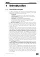
1.1 Instrument description 1 Introduction 1.1 Instrument description The 746 VA Trace Analyzer is a microprocessor-controlled measuring instrument for universal use in polarographic and voltam(pero)metric analyses. The two concepts polarography and voltammetry are defined as follows: Polarography Polarography is the measurement of current/voltage curves recorded at electrodes whose material is liquid and whose surface is renewed periodically or continuously.
1 Introduction 1.2 Information about the Instructions for Use Please read through these Instructions for Use carefully before you put the 746 VA Trace Analyzer and 747 VA Stand into operation. The Instructions for Use contain information and warnings to which the user must pay attention in order to assure safe operation of the instruments. 1.2.1 Organization These 8.746.
1.2 Information about the Instructions for Use 1.2.2 Notation and pictograms The following notations and pictograms (symbols) are used in these Instructions for Use: "SAMPLES" Dialog page Key Softkey Mode Parameter or entry value ........ Modifiable parameter XXXXXXXX Displayed parameter (not modifiable) 15 Part or control of 746/747 Hazard This symbol draws attention to a possible danger to life or of injury if the associated directions are not followed correctly.
1 Introduction 1.3 Support documentation Application Bulletins The «Application Bulletin» is a collection of analytical methods, application examples and literature references. Of Metrohm's approximately 200 Application Bulletins, ca. 60 refer to Polarography and Voltammetry. All these Application Bulletins are available on request free of charge from your Metrohm supplier.
1.3 Support documentation No.
1 Introduction Application Notes The «Application Notes» present application information in concentrated form, i.e. on maximum 2 pages. In the field of voltammetry, there are at present approximately 60 Application Notes (in English). You can order these free of charge from your Metrohm supplier or view them in the Internet under «http://www.metrohm.ch» and copy them from there. 1-6 No.
1.3 Support documentation No.
1 Introduction Monographs The «Metrohm Monographs» listed below impart theoretical fundamentals and general information on measurement techniques and sample preparation of polarography and voltammetry. All these monographs are available on request free of charge from your Metrohm supplier. Title First aid for polarography and voltammetry (8.693.
2.1 746.0010 VA Trace Analyzer 2 Parts and controls In this section you will find the numbers and designations of the parts and controls of the 746 VA Trace Analyzer and the 747 VA Stand. The numbering applies throughout the instructions for use, i.e. bold numbers in the text (e.g. 15) 15 refer to the parts and controls illustrated here.
2 Parts and controls 2.1 746.0010 VA Trace Analyzer 1 2 3 4 5 Fig. 1: Front of the 746.0010 VA Trace Analyzer 2-2 1 Screen (LCD) setting the contrast, see section 5.3.1 4 Mains pilot lamp lit up when instrument switched on 2 Eject button for data card pressing this button ejects the inserted data card 5 Keypad (piezoelectric keypad) key designations and explanations, see section 5.1 3 Slot for data card (standard JEIDA 4.
2.1 746.0010 VA Trace Analyzer 7 8 Printer Type 1.746.0010 9 External Bus Dos. 1 Dos. 3 RS 232 Interface 1 Dos. 2 Dos. 4 RS 232 Interface 2 0 I WARNING - Fire Hazard For continued protection replace only with the same type and rating of fuse Control Lines 115V 2A(TH) 230V 230V 115V: 100V...120V±10% 230V: 220V...240V±10% 23 22 21 20 S 50-60Hz 160VA 19 18 17 16 15 14 11 12 Reset Made by Metrohm Herisau Switzerland 10 13 Fig. 2: Rear of the 746.
2 Parts and controls 2.2 746.0020 VA Trace Analyzer 6 1 2 3 4 5 Fig. 3: Front of the 746.0020 VA Trace Analyzer 2-4 1 Screen (LCD) setting the contrast, see section 5.3.1 4 Mains pilot lamp lit up when instrument switched on 2 Eject button for data card pressing this button ejects the inserted data card 5 Keypad (piezoelectric keypad) key designations and explanations, see section 5.1 3 Slot for data card (standard JEIDA 4.
2.2 746.0020 VA Trace Analyzer 7 8 Type 1.746.0010 9 External Bus Dos. 1 Dos. 3 RS 232 Interface 1 Dos. 2 Dos. 4 RS 232 Interface 2 0 I WARNING - Fire Hazard For continued protection replace only with the same type and rating of fuse Control Lines 115V 2A(TH) 230V 230V 115V: 100V...120V±10% 230V: 220V...240V±10% 23 22 21 20 S 50-60Hz 160VA 19 18 17 16 15 11 12 Reset Made by Metrohm Herisau Switzerland 10 13 Fig. 4: Rear of the 746.
2 Parts and controls 2.3 747.0010 VA Stand 24 25 26 27 28 29 Fig. 5: Front of the 747.0010 VA Stand 2-6 24 Cover of measuring head arm hinged 27 Gas wash bottle (6.2405.030) for inert gas supply (filling with dist. water, see section 3.3.1) 25 Stopper (6.2709.080) to close the pipetting opening 28 Measuring vessel when measuring head arm is fully raised, the measuring vessel can be pulled forward out of the holder 26 26 Holder for measuring vessel 29 Drip pan (6.2711.
2.3 747.0010 VA Stand 30 31 32 33 Made by Metrohm Herisau Switzerland Type 1.747 34 External Bus Address 35 36 Fig. 6: Rear of the 747.0010 VA Stand 30 Connection for inert gas lead-off 34 External Bus (EBUS) connection socket for 6.2135.000 EBUS Connecting cable (connection to 746 VA Trace Analyzer) 31 Connection for waste solution lead-off (see section 3.10.5) 35 Stand address First stand: 1 Second stand: 2 Third stand: 3 (setting stand address see section 3.3.
2 Parts and controls 37 38 25 39 40 41 42 43 44 45 46 43 47 48 49 27 50 51 47 52 53 54 Fig. 7: Right side view of the 747.0010 VA Stand (fully equipped) 55 56 57 58 37 59 38 25 60 40 41 71 70 69 68 67 52 66 65 64 49 63 60 46 62 61 Fig. 8: Left side view of the 747.
2.3 747.0010 VA Stand 25 Stopper (6.2709.080) to close the pipetting opening 48 Electrode cable ”RE” connection for reference electrode 43 27 Gas wash bottle (6.2405.030) for inert gas supply (must be filled halfway with dist. H2O, see section 3.3.3) 49 Drive belt (6.1244.020) connection between drive wheel 52 and drive shaft 45 37 Electrode cable ”WE” connection for working electrode (MME or RDE) 50 PTFE tube (4.647.
2 Parts and controls 64 65 2-10 PTFE tube (6.1819.010) for supply of the waste solution to gas wash bottle 65 (attached); see section 3.3 68 Dummy cell connection ”WE-L” linear mode simulation (RC element) 69 Dummy cell connection ”RE” Gas wash bottle (6.2405.
3.1 Setting up the instruments 3 Installation This section offers a full description of the 746 VA Trace Analyzer and the 747 VA Stand and provides detailed information on the various electrodes and the stirrer. Reliable operation of the these instruments is assured only if you follow the instructions in this section exactly. 3.1 Setting up the instruments 3.1.
3 Installation 3.2 Installation of 746 VA Trace Analyzer Follow the instructions below for connecting to the power supply. If the instrument is operated with the mains voltage set wrongly and/or wrong mains fuse there is a danger of fire! 3.2.1 Setting the instrument supply voltage Before switching on the 746 VA Trace Analyzer for the first time, check that the mains voltage set on the instrument (visible in mains voltage selector 9) matches the local power supply voltage.
3.2 Installation of 746 VA Trace Analyzer 3.2.3 Mains cable and mains connection The instrument is supplied with one of three mains cables: • 6.2122.020 with plug SEV 12 (Switzerland, …) • 6.2122.040 with plug CEE(7), VII (Germany, …) • 6.2133.070 with plug NEMA 5-15 (USA, …) which are three-cored and fitted with a plug with an earthing pin. If a different plug has to be fitted, the yellow/green lead (IEC standard) must be connected to protective earth (protection class I).
3 Installation 3.2.6 Handling of data cards The 746 VA Trace Analyzer offers the possibility of writing data to SRAM memory cards and reading data from such cards. The following data cards or memory cards can be used: • 6.2245.010 Metrohm Data Card (capacity 128 kB) • Commercial SRAM cards of any capacity with the JEIDA 4.0 hardware format (68 pins) as well as PCMCIA cards based on these Owing to differing file systems, PCMCIA cards can not be used simultaneously for the 746 VA Trace Analyzer and PCs.
3.2 Installation of 746 VA Trace Analyzer • The data card must be formatted before it can be used to store data. Proceed as follows: − Insert data card in the 746 VA Trace Analyzer (see point ”Inserting data card”). − Select dialog page ”DATA CARD”. The message WARNING: Data card not formatted or battery down appears followed by the inquiry do you want to [f]ormat, [c]ontinue, [q]uit ? − Enter f for format. With the inquiry Label of the Data card ?, you are then prompted to enter a title for the card.
3 Installation 3.3 Installation of 747 VA Stand If the 746 VA Trace Analyzer is connected to the power supply, neither the 746 VA Trace Analyzer nor the 747 VA Stand may be opened or parts removed as there is a danger of contact with live components. Before the 746 VA Trace Analyzer or 747 VA Stand is opened to change components or for maintenance or repair work, the mains cable must thus always be disconnected from the mains connection plug 13 of the 746 VA Trace Analyzer! 3.3.
3.3 Installation of 747 VA Stand 3 3.3.2 Attachment of a 747 VA Stand for the 695 Autosampler • Switch off 746 VA Trace Analyzer using the mains switch 11. 11 • Plug one end of the third 6.2135.000 EBUS cable into connector of the second EBUS cable and fasten together by tightening the screws in the cable connector. • Plug the other end of the third EBUS cable into connection 34 of the third 747 VA Stand and fasten to the instrument by tightening the screws in the cable connector.
3 Installation 4 Install stirrer or RDE in operation with MME: • Screw stirrer tip 63 to drive shaft 45 (see also section 3.8). • Insert stirrer in opening 81 as far as it will go. • Stretch drive belt 49 (6.1244.020) between drive wheel 52 and drive shaft 45 of the stirrer. in operation with RDE (option): • Screw electrode tip 120 (6.1204.XXX) to drive shaft 121 (6.1246.000) (see also section 3.5). • Insert RDE in opening 81 as far as it will go. • Stretch drive belt 49 (6.1244.
3.3 Installation of 747 VA Stand 40 Measuring head arm 41 Measuring head 72 Opening for auxiliary electrode 60 (6.0343.000 Pt auxiliary electr. or optional GC electr. comprising 6.1241.020 Electrode holder and 6.1247.000 GC tip) 73 Threaded opening without automatic rinsing: for dummy stopper 62 (6.1446.040) with automatic rinsing: for FEP tubing 89 (6.1805.180) 74 Threaded opening without automatic rinsing: for dummy stopper 61 (6.1446.040) with automatic rinsing: for FEP tubing 90 (6.1805.
3 Installation 7 Install MME or dummy stopper in operation with MME: • Carefully insert multi-mode electrode 38 (6.1246.020) in opening 76 (the underside of the capillary must not touch the measuring head during insertion) and push in as far as it will go. • Screw FEP tubing 51 (6.1805.180) for inert gas supply into connection 93 of the MME 38. 38 • Screw FEP tubing 59 (6.1805.180) for inert gas supply into connection 94 of the MME 38.
3.3 Installation of 747 VA Stand 55 89 90 40 41 91 92 66 65 64 Fig. 10: Install accessories for rinsing and siphoning off 40 Measuring head arm 89 FEP tubing (6.1805.180) for transferring the waste solution to gas wash bottle 65 41 Measuring head 55 FEP tubing (6.1805.100) for waste solution lead-off (attached) 90 FEP tubing (6.1805.100) for supply of the rinsing solution 64 PTFE tube (6.1819.010) for supply of the waste solution to gas wash bottle 65 91 PTFE tube (6.1819.
3 Installation 3.3.3 Inert gas connection Nitrogen (N2) is generally used as the inert gas to deaerate the analyte solution and for operation of the MME. The nitrogen must be of sufficient purity. w(N2) ≥ 0.99996 (= 99.996%) for general polarography/voltammetry w(N2) ≥ 0.99999 (= 99.999% = "5 × 9") for analyses in organic solvents; for determinations involving very high current amplification (e.g.
3.3 Installation of 747 VA Stand Fig. 11: Scheme showing the inert gas connections at the 747 VA Stand 27 Gas wash bottle (6.2405.030) for inert gas supply (must be filled only halfway with dist. H2O or supporting electrolyte, see also Fig. 7) 54 Slotted screw for controlling the inert gas flow for deaeration (see also Fig. 7) Note: The factory setting of ca. 20 L/h should not be changed without good reason! 71 Slotted screw for controlling the tapping power in the DME case (see also Fig.
3 Installation 3.4 Multi-mode electrode (MME) The multi-mode electrode combines the most important polarographic and voltammetric mercury electrodes in a single construction: 3.4.1 • HMDE Hanging mercury drop electrode Mercury is forced through a glass capillary until a drop forms at the capillary tip and the entire voltage sweep performed on this single stationary drop; in general with preceding enrichment (stripping voltammetry).
3.4 Multi-mode electrode (MME) 95 96 97 98 94 99 100 93 101 93 Connection for inert gas supply 94 Connection for inert gas supply (for all MME operating modes) 95 Locking ring (4.420.2920) for slotted screw 96 96 Slotted screw (3.420.3920) with PTFE membrane and built-in spring 97 Sealing needle (6.1247.020) 98 Screw thread for slotted screw 96 99 Unused connection 102 103 104 105 106 100 Screw thread for slotted screw 101 101 Slotted screw (4.420.
3 Installation 3.4.2 Filling the MME with mercury When handling mercury, it is necessary to take special precautionary measures. These are described in detail in section 7.2. All actions involving the electrode and mercury vessels must be performed in or over the drip pan 113 supplied (see Fig. 14). The Hg reservoir 103 of the multi-mode electrode 38 is filled with mercury of the highest degree of purity (mass fraction w ≥ 0.
3.4 Multi-mode electrode (MME) 3.4.3 2 Draw up mercury • Attach needle 112 to syringe 111. 111 • Draw up 6 mL ultrapure mercury slowly and carefully using syringe 111. 111 3 Add mercury to MME • Lower syringe needle 112 into the top opening of the MME 38 between sealing ring 106 and sealing needle 97. 97 • Expel mercury slowly and carefully from the syringe to allow it to flow into the Hg reservoir 103.
3 Installation 3.4.4 Filling the capillary without vacuum The glass capillary 109 can normally be filled with mercury by the method described here without vacuum. However, if difficulties regarding stability or reproducibility arise with a capillary filled in this manner, try to fill the capillaries by the alternative method with vacuum (section 3.4.5). To fill the mounted glass capillary 109 (section 3.4.
3.4 Multi-mode electrode (MME) • Gently tap the MME with your finger and turn the slotted screw 96 very slowly clockwise until the mercury flow just stops. (The tapping action is used to knock off the mercury drops so that it is easier to see whether mercury continues to flow.) • Finally, turn slotted screw 96 a quarter of a turn clockwise. 5 Checking the MME for leaks • Select dialog page "STAND" then switch on the dropping mercury electrode by pressing the softkey .
3 Installation 118 115 Pump 116 109 Vacuum release tap 38 113 117 114 117 Fig. 14: Setting up the filling station Vacuum 115 Vacuum 116 1 2 109 3 113 114 38 Fig. 15: Filling the capillary 38 3-20 Multi-mode electrode (6.1246.0020) 115 Filling tubing (6.1817.000) 109 Glass capillary (6.1226.030) 116 Filling cone (4.420.2860) (part of the filling tubing 115) 115 113 Drip pan (6.2711.030) 117 Gas wash bottle 114 Electrode holder (6.2615.030) 118 Tubing coupling (6.1809.
3.4 Multi-mode electrode (MME) 5 Evacuating in vertical position • Place multi-mode electrode 38 vertically in the electrode holder 114 (see Fig. 15-1). • Evacuate for ca. 2 min in this position. 6 Evacuating in inclined position • Carefully tilt multi-mode electrode 38 in the electrode holder 114 to an inclined position and continue evacuating (see Fig. 15-2).
3 Installation 10 Pressurize the MME • Switch on 746 VA Trace Analyzer with mains switch 11 (746 VA Trace Analyzer and 747 VA Stand must first be installed properly as described in section 3.2 and section 3.3). • Select dialog page "STAND" and then switch on the inert gas supply to the 747 VA Stand by pressing the softkey . This pressurizes the multi-mode electrode 38 and the mercury begins to flow slowly out of the capillary.
3.4 Multi-mode electrode (MME) 3.4.7 Replenishing the mercury (without changing capillary) The multi-mode electrode 38 can also be refilled with mercury without having to remove the glass capillary 109. 109 1 Dismantle multi-mode electrode • Unscrew FEP tubing 51 and 59 from the MME. Disconnect electrode cable 37 from the MME. • Take multi-mode electrode 38 out of the measuring head 41 and tap the MME gently to knock off any mercury drops on the glass capillary into the measuring vessel.
3 Installation 3.4.8 Changing the capillary Contamination of the glass capillary can necessitate its replacement (see also sections 7.4.2 and 7.4.3). In such a case, proceed as follows: 3-24 1 Remove multi-mode electrode from 747 VA Stand • Unscrew FEP tubing 51 and 59 from the MME, disconnect electrode cable 37 from MME. • Take multi-mode electrode 38 out of measuring head 41 while gently tapping the MME to knock off any mercury drops on the glass capillary into the measuring vessel.
3.4 Multi-mode electrode (MME) 3.4.9 Cleaning the MME If the mercury in the multi-mode electrode is contaminated and this leads to disturbances (see sections 7.4.2 and 7.4.3), the MME must be cleaned and refilled with ultrapure mercury. Proceed as follows: 1 Remove multi-mode electrode from 747 VA Stand • Unscrew FEP tubing 51 and 59 from the MME, disconnect electrode cable 37 from MME.
3 Installation 6 Replace sealing needle 97 if need be If problems with leaks arise owing to a worn, deformed or damaged sealing needle 97 (see sections 7.4.2 and 7.4.3), this must be replaced. Three spare needles are supplied separately in a protective plastic package. After unpacking a needle, please avoid any contact whatsoever with the needle tip. The spare needle 97 is installed as follows: • Carefully pull old sealing needle 97 out of PTFE membrane of the slotted screw 96.
3.5 Rotating disk electrode (RDE) 3.5 Rotating disk electrode (RDE) The rotating disk electrode (RDE) is available as an option and can be used in place of the MME in the 747 VA Stand with different electrode tips as a working electrode. The following accessories have to be ordered (see also section 9.4): 3.5.1 • 6.1246.000 Drive shaft for rotating electrode • 6.1204.XXX Electrode tip for rotating electrode 6.1204.100 Ultra Trace Graphite 6.1204.110 GC (Glassy Carbon) 6.1204.120 Pt 6.1204.130 Ag 6.
3 Installation 55 56 57 58 37 51 119 25 60 40 41 52 49 59 121 120 60 Fig. 16: Measuring head arm with rotating disk electrode (RDE) 25 Stopper (6.2709.080) to close the pipetting opening 37 Electrode cable ”WE” connection for working electr. (RDE) 40 Measuring head arm carrier plate with permanently attached measuring head, raisable 41 49 3-28 Measuring head measuring vessel upper half made of PTFE; with openings for electrodes, stirrer, gas and liquid supply lines Drive belt (6.1244.
3.6 Reference electrode 3.6 Reference electrode 3.6.1 Construction The complete reference electrode (RE) 43 comprises two parts: • 6.0728.0X0 Ag/AgCl reference system (122 122) with ceramic diaphragm type D, diameter = 1 mm 6.0728.020 Reference system: Ag/AgCl/c(KCl) = 3 mol/L; supplied in a holder filled with c(KCl) = 3 mol/L as standard 6.0728.010 Reference system: Ag/AgCl supplied dry (option) • 6.1245.
3 Installation 3.6.2 Startup procedure The reference electrode 43 is supplied in modular form as the reference system 122 and the electrolyte vessel 123 and has first to be filled and assembled as follows: 1 Add internal electrolyte Filling of the reference system is necessary only when the optional 6.0728.010 Reference system supplied dry is used, if the internal electrolyte solution has to be renewed or if the electrical connection is interrupted by gas bubbles.
3.7 Auxiliary electrode 3.7 Auxiliary electrode 3.7.1 Construction The following electrodes can be used as the auxiliary electrode 60 (AE): • 6.0343.000 Pt auxiliary electrode supplied as standard • 6.1241.020 6.1247.000 Electrode holder and Glassy carbon tip together form the glassy carbon auxiliary electrode available as an option The construction of the two auxiliary electrodes and the designations of the individual parts are shown in Fig. 18. 3.7.2 Startup procedure The 6.0343.
3 Installation 60 133 60 133 Electrical connection for cable "AE" 134 Pt Auxiliary electrode (6.0343.000) 135 Pt tip (permanently attached) 136 Electrode holder (6.1241.020) 137 Locking ring 138 Glassy carbon tip (6.1247.000) 133 136 134 137 138 135 Auxiliary electrode Fig. 18: Construction of the auxiliary electrode 3.8 Stirrer The complete stirrer comprises two parts (see also Fig. 8): • 6.1246.010 Drive shaft (45 45) • 6.1204.
3.9 Connection of 685 Dosimats 3.9 Connection of 685 Dosimats Up to four 685 Dosimats can be attached to the 746 VA Trace Analyzer for the automatic addition of standard and auxiliary solutions. The 685 Dosimat and the accessories needed have the following ordering designations (see also section 9.5): • 2.685.0010 Dosimat • 6.2134.000 Cable 685 – 746 • 6.3014.XXX Exchange unit, with PCTFE/PTFE flat stopcock 6.3014.153 burette volume V = 5 mL 6.3014.213 burette volume V = 10 mL 6.3014.
3 Installation 3.9.2 Tubing connection for addition of standard solutions For the addition of standard solutions in the µL-range into the measuring vessel of the 747 VA Stand the 4-way microtip 47 (6.1824.000) should be used. It is fitted with 4 lengths of PTFE tubing with connection nipples for direct attachment to the Exchange unit of the 685 Dosimat.
3.9 Connection of 685 Dosimats 3.9.3 Tubing connection for addition of auxiliary solutions The 4-way microtip 47 is not suited for the addition of auxiliary solutions in the mLrange into the measuring vessel of the 747 VA Stand. For the addition of a first auxiliary solution we recommend the use of the following accessories: • 1 × 6.1819.000 • 2 × 6.1805.100 • 1 × 6.1808.000 PTFE tube, length L = 77 mm, i.d. = 0.8 mm FEP tubing, length L = 40 cm, i.d.
3 Installation For the addition of a second auxiliary solution we recommend the use of the following accessories: • • • • 1 × 6.1446.070 1 × 6.1819.000 2 × 6.1805.100 1 × 6.1808.000 Stopper, with M6 thread PTFE tube, length L = 77 mm, i.d. = 0.8 mm FEP tubing, length L = 40 cm, i.d. = 2 mm Coupling To install these accessories and ready the 685 Dosimat for automatic dispensing, proceed as follows: 3-36 1 Mount Exchange unit on 685 Dosimat • Procedure, see section 2 of 685 Instructions for Use.
3.9 Connection of 685 Dosimats 3.9.4 Changing the Exchange unit The Exchange unit mounted on the 685 Dosimat can be changed only in the exchange position. Please proceed as follows: 1 Switch to exchange position • Select dialog page "DOSIMATS". • Select desired Dosimat with the cursor keys and press softkey : The Dosimat is switched to the exchange position and the parameter Position is set to exchange.
3 Installation 3.9.5 Installation and use of the pipetting equipment The optional available Pipetting equipment is suited for pipetting and automatic dilution functions with 685 Dosimats. The following accessories have to be ordered in addition to the standard equipment of the 747 VA Stand (see section 9.4 and 9.5): • • • • 1 × 2.685.0010 1 × 6.2134.000 1 × 6.3014.213 1 × 6.5611.
3.9 Connection of 685 Dosimats 5 Prepare waste beaker • Put 6.2754.000 Rinsing quiver onto the lip of an empty waste beaker. Before starting any initialization, dilution or pipetting functions with the pipetting handle, hold the pipetting handle so that any solution leaving the pipetting tip is expelled into the waste beaker. 6 Initialize Dosimat • Switch on 746 VA Trace Analyzer using the mains switch 11. 11 • Select dialog page "DOSIMATS". • Set parameter V.tube in for the desired Dosimat to 1.7 mL.
3 Installation 8 3-40 Use pipetting handle in an operation sequence • Make sure that the 685 Dosimat with the connected pipetting handle is connected to the "Dos.1" socket of the 746 VA Trace Analyzer. • Enter the desired dispensing instructions for which the pipetting handle should be used on the "OP. SEQUENCE" and/or "SEGMENTS" page. If you enter a solution name Soln.name for this solution, make sure that no Dosimat is assigned for this solution on the "SOLUTIONS" page (parameter Pos. must be empty).
3.10 Connection of 700 Dosinos 3.10 Connection of 700 Dosinos Up to four 700 Dosinos can be attached to the 746 VA Trace Analyzer for the automatic addition of standard and auxiliary solutions. The 700 Dosino and the Dosing Units needed for the addition have the following ordering designations (see also section 9.5): • 2.700.0010 • 6.3030.XXX Dosino Dosing unit, with ETFE burette cylinder 6.3030.120 cylinder volume V = 2 mL 6.3030.150 cylinder volume V = 5 mL 6.3030.210 cylinder volume V = 10 mL 6.3030.
3 Installation 3.10.2 Tubing connection for addition of standard solutions For the addition of standard solutions in the µL-range into the measuring vessel of the 747 VA Stand the 4-way microtip 47 (6.1824.000) should be used. It is fitted with 4 lengths of PTFE tubing with connection nipples for direct attachment to the Dosing unit of the 700 Dosino. To ready the 700 Dosino for automatic dispensing, proceed as follows: 3-42 1 Mount Dosing unit on 700 Dosino • Procedure, see section 2.
3.10 Connection of 700 Dosinos 3.10.3 Tubing connection for addition of auxiliary solutions The 4-way microtip 47 is not suited for the addition of auxiliary solutions in the mLrange into the measuring vessel of the 747 VA Stand. For the addition of a first auxiliary solution we recommend the use of the following accessories: • 1 × 6.1819.000 • 2 × 6.1805.100 • 1 × 6.1808.000 PTFE tube, length L = 77 mm, i.d. = 0.8 mm FEP tubing, length L = 40 cm, i.d.
3 Installation For the addition of a second auxiliary solution we recommend the use of the following accessories: • • • • 1 × 6.1446.070 1 × 6.1819.000 2 × 6.1805.100 1 × 6.1808.000 Stopper, with M6 thread PTFE tube, length L = 77 mm, i.d. = 0.8 mm FEP tubing, length L = 40 cm, i.d. = 2 mm Coupling To install these accessories and ready the 700 Dosino for automatic dispensing, proceed as follows: 3-44 1 Mount Dosing unit on 700 Dosino • Procedure, see section 2.2 of 700 Instructions for Use.
3.10 Connection of 700 Dosinos 3.10.4 Changing the Dosing unit If the Dosing unit is changed when the Dosino is in the dosing position, the Dosino can get destroyed! Therefore always make sure that the Dosino is in the exchange position (see parameter Position on dialog page "DOSIMATS") before changing the Dosing unit. The Dosing unit mounted on the 700 Dosino can be changed only in the exchange position. Please proceed as follows: 1 Switch to exchange position • Select dialog page "DOSIMATS".
3 Installation 3.10.5 Installation of Dosinos for rinsing the measuring vessel It is possible to rinse the measuring vessel at the 747 VA Stand manually via dialog page "STAND" or with the RINSE command by means of two 700 Dosinos with 50 mL Dosing units. To do this, the following accessories have to be ordered in addition to the standard equipment of the 747 VA Stand (see also section 9.4): • 2 × 2.700.0010 • 1 × 6.5323.
3.10 Connection of 700 Dosinos 7 Connect siphoning Dosino to 747 VA Stand • Using either a 6.1805.120 FEP Tubing (L = 1 m) or two 6.1805.120 FEP Tubings and a 6.1808.000 Connecting sleeve, connect connection 1 of the 6.1567.250 Dosing unit of the siphoning Dosino with coupling 31 mounted on the 747 VA Stand (see Fig. 6). • Attach siphoning Dosino using the cable connected to the instrument to socket 18 (Dos. 4) of the 746 VA Trace Analyzer (see Fig. 2 or Fig. 4).
3 Installation 3.10.6 Installation and use of the pipetting equipment The optional available Pipetting equipment is suited for pipetting and automatic dilution functions with 700 Dosinos. The following accessories have to be ordered in addition to the standard equipment of the 747 VA Stand (see section 9.4 and 9.5): • 1 × 2.700.0010 • 1 × 6.1567.210 • 1 × 6.5611.
3.10 Connection of 700 Dosinos 6 Initialize Dosino • Switch on 746 VA Trace Analyzer using the mains switch 11. 11 • Select dialog page "DOSIMATS". • Set parameter V.tube in of the desired Dosino to 0.7 mL. • Set parameter V.tube out of the desired Dosino to 4.8 mL. • Take pipetting handle by hand and put it into the waste beaker with the pipetting tip down.
3 Installation • Put the pipetting handle into the waste beaker so that the pipetting tip is at about the same level as the container with the solution that should be pipetted and press the black button on the handle (if you press at this time, you would have to add the solution manually). • If the pipetting instruction is carried out for the first time or if the previous pipetting instruction has been terminated by (see below), the message Preparing Dosimat #X appears.
3.11 Connection of printers via parallel interface 3.11 Connection of printers via parallel interface The 746.0010 VA Trace Analyzer has a parallel interface dedicated to connect external printers with parallel interfaces. The external printers are connected to the printer connection 14 of the 746 VA Trace Analyzer by means of the cable delivered with the printer (see Fig. 23).
3 Installation 746 Control Lines External Bus Dos. 1 Dos. 3 RS 232 Interface 1 Dos. 2 Dos. 4 RS 232 Interface 2 115V 2A(TH) 230V 230V Printer 0 I Reset Printer cable Fig. 23: Connection of a printer to 746.0010 VA Trace Analyzer 3.12 Connection of devices via RS232 interfaces The 746 VA Trace Analyzer has two interfaces 16 and 17 of type RS232C, which are identical in hardware terms but differ with regard to software (in the functioning of the 746 VA Trace Analyzer) (see Fig.
3.12 Connection of devices via RS232 interfaces RS232 interface 1 PC 746 230V Printer External Bus Dos. 1 Dos. 3 RS 232 Interface 1 Dos. 2 Dos. 4 RS 232 Interface 2 115V 2A(TH) 230V Control Lines 0 I Reset Printer RS232 interface 2 Balance Fig. 24: Connection possibilities for the RS232 interfaces 3.12.
3 Installation 3.12.2 Connection of a printer External printers with a serial interface can be attached to the two RS232 interfaces of the 746 VA Trace Analyzer. For several printers, connecting cables are available as an option (see section 9.5). The type of the printer is selected on dialog page "VA TRACE ANALYZER". The following printer drivers are available (see also section 5.3.1): IBM Propr.
3.12 Connection of devices via RS232 interfaces 3.12.3 Connection of a balance The balances listed below can be attached to RS232 interface 2 of the 746 VA Trace Analyzer. The settings of the RS232 parameters on the 746 VA Trace Analyzer depend on the settings of the balance, Receive mode must be set to on. Balance Cable Settings on 746 VA Trace Analyzer Sartorius MP8, MC1 6.2125.
3 Installation 3.13 Connection of devices via remote interface The 746 VA Trace Analyzer is fitted with a 25-pin remote interface (connection 23 ”Control Lines”) with a total of 16 control lines. Any external device can be attached to the 8 inputs (scan) and 8 outputs (set) and can be scanned or set via these lines. The current status of the control lines at the 746 VA Trace Analyzer is shown on the ”VA TRACE ANALYZER” page as follows (see section 5.3.
3.13 Connection of devices via remote interface 746 230V Printer External device External Bus Dos. 1 Dos. 3 RS 232 Interface 1 Dos. 2 Dos. 4 RS 232 Interface 2 115V 2A(TH) 230V Control Lines 0 I Reset Remote cable Fig.
3 Installation 3-58 746 VA Trace Analyzer / 747 VA Stand
4.1 Preparations 4 Introduction to the operation This section uses simple examples to introduce you to the operation of the 746 VA Trace Analyzer and the 747 VA Stand. These examples have been so selected that both the routine operation and the most important instrument possibilities are demonstrated. You will find general, more detailed explanations and information in framed, italicized text blocks. The illustrative methods can also be used as starting methods for concrete, analytical determinations.
4 Introduction to the operation 4.1 Preparations In order to be able to perform the illustrative methods described in section 4.2 ff, you must first put the 746 VA Trace Analyzer and 747 VA Stand into operation in a proper manner. Proceed as described in section 4.1.1 and section 4.1.2 (you will find information regarding the installation in the specified subsections of section 3). Additional preparations required involve several instrument settings for the 746 VA Trace Analyzer (section 4.1.
4.1 Preparations 4.1.3 6 Inserting reference electrode • Inserting reference electrode in measuring head and connecting Section 3.3.2 7 Inserting Pt auxiliary electrode • Inserting Pt auxiliary electrode in measuring head and connecting Section 3.3.2 8 Filling MME • Filling multi-mode electrode (MME) with mercury, mounting capillary and filling Section 3.4 9 Inserting MME • Inserting multi-mode electrode (MME) in measuring head and connecting Section 3.3.
4 Introduction to the operation 746 VA TRACE ANALYZER Program 5.746.0101 Date Time Beeper 1997-03-20 10:41:15 on Display ––––––––––––––––––––––––––––– Switch–off time 30 min Contrast 106 Configuration Address ––––––––––––––––––––––––––––– VA stand 1 RS232 settings Ifc.1 Ifc.2 –––––––––––––––––––––––––––––––––––––––––––– Baud rate 9600 9600 Data bits 8 8 Stop bit(s) 1 1 Parity none none Handshake Hwshort Hwshort Receive mode off off Balance type Printer type Printer width Remote keyboard none 1.
4.1 Preparations In addition to the softkey , with parameters for which only certain numeric values or text expressions can be entered, further softkeys with these numbers or texts appear as keying-in aids. By pressing these softkeys, the corresponding expression is entered directly in the entry field and the field closed. • Enter the desired date in the order year – month – day in the format YYYY-MM-DD and confirm the entry by pressing the key.
4 Introduction to the operation 4.1.4 Tests to check the 747 VA Stand The tests described below are used to check the functions of the 747 VA Stand such as purging, stirrer, DME and HMDE required for the illustrative methods. Perform the tests as follows (if the 746 VA Trace Analyzer is switched on, you can start directly with point 2): 1 Switch on instrument • Switch on the 746 VA Trace Analyzer with mains switch 11 at the rear of the instrument. The instrument is initialized.
4.1 Preparations 4 Testing stirrer • Press the softkey . The stirrer is switched on, at the same time the display for Stirrer switches to on and an asterisk * appears in the softkey of the same name. • Check whether the stirrer functions properly. If so, you can switch off the stirrer by pressing the softkey . • If the stirrer does not function properly, check its installation as described in section 3.8 and then repeat the test. Stirring serves to mix the analysis solution thoroughly.
4 Introduction to the operation 747 VA STAND Manual Address 1 Switches ÄÄÄÄÄÄÄÄÄÄÄÄÄÄÄ Pressure off Purging off Stirrer off DME HMDE SMDE RDE off off off off Settings ÄÄÄÄÄÄÄÄÄÄÄÄÄÄÄÄÄÄÄÄÄÄ Rot.speed 2000 /min Drop size Drop size Rot.speed 5 5 2000 /min V.meas max 80 mL VA Stand VA Stand 695 Auto 717 Smpl 1 2 sampler Changer 8 Rinsing Dosinos States ÄÄÄÄÄÄÄÄÄÄÄÄÄÄÄÄÄÄÄÄÄÄÄÄÄ U.standby --- mV Electr. Default test values >> Switches Electrode test of the DME • Press the softkey .
4.2 Lead determination with standard addition 4.2 Lead determination with standard addition With the aid of this illustrative method for the determination of lead in the ion standard solution supplied, you can easily check whether the 746 VA Trace Analyzer and the 747 VA Stand are functioning properly. At the same time, you will learn how to set up a method with standard addition and will be introduced to the basic operation of the 746 VA Trace Analyzer.
4 Introduction to the operation The header of dialog page "METHODS" contains details of the number of stored methods and the available storage space. This is followed by the names of all stored methods displayed in 4 columns. You obtain a different type of display if you press the softkeyy . In addition to the name of the method, its content (method title) and memory requirements are shown. You will find further information regarding the dialog page "METHODS" in section 5.4.1. 4.2.
4.2 Lead determination with standard addition The dialog page "OPERATION SEQUENCE" contains a sequence of program instructions which can be freely combined. Most of the instructions also have certain main and auxiliary parameters as well as optional entry of a line time. A total of 88 different program instructions can be used to program any type of determination. You will find further information regarding this dialog page in section 5.6.
4 Introduction to the operation • The sequence of the segment SegPb is explained in brief in what follows: 3 Line 1 Switching on the DME (dropping mercury electrode) Line 2 Selection of the measurement mode DP (differential pulse) with voltage amplitude –50 mV, voltage step 0.4 s, measurement time 20 ms and pulse time 40 ms Line 3 Voltage sweep of –200 mV ...
4.2 Lead determination with standard addition dU.front/dU.rear Determination of base points: automatic S.front/S.rear Determination of the slopes at the base points: automatic I.scale Scaling of the current axis: automatic U.div Division of the voltage axis for printout Quantity Evaluation quantity: peak height • Press the softkey < >> >.
4 Introduction to the operation Method: TESTPb Quantity ÄÄÄÄÄÄÄÄÄÄÄÄ ÄÄÄÄÄÄÄÄ Pb Modify column CALCULATION max. 15 lines Formula (R##, C##, A##) ÄÄÄÄÄÄÄÄÄÄÄÄÄÄÄÄÄÄÄÄÄÄÄÄÄÄÄÄÄÄÄÄÄÄÄÄÄÄÄÄ Res.unit Sig.dig. ÄÄÄÄÄÄÄÄ R1000=MC:Pb #g/L Modify line Delete line Insert line New calcul. Upd.from method 4 Syntax check On the dialog page "CALCULATION", maximum 15 formulae for the calculation of the final results as well as the designations of the result quantities and units can be entered.
4.2 Lead determination with standard addition The dialog page "DOCUMENTATION" can be used for the entry of reports and curves which should be put out automatically to the specified destination at the end of the determination. A single line or all these lines can also be executed later using the softkeyy or . You will find further information regarding this dialog page in section 5.6.5.
4 Introduction to the operation 4.2.4 Preparing the sample solution The sample solution for the lead determination is prepared as follows: 4.2.5 1 Addition of 20 mL dist. water • Add 20 mL dist. or deion. water to the measuring vessel. 2 Addition of 0.5 mL KCl 3 mol/L • Add 0.5 mL potassium chloride c(KCl) = 3 mol/L to the measuring vessel.
4.2 Lead determination with standard addition 2 Entry of the sample volume Enter the sample volume as follows: • Use the cursor keys to select the first field below the title Sample size/S0. • Press the space bar to enter the edit mode (this step can be omitted as the entry of a number switches directly to the edit mode). • Enter 0.1 mL and confirm this entry with the key.
4 Introduction to the operation Further, you can also select all dialog pages with the exception of "STAND" and "CURVES" and make changes to them. But be careful when making such changes as they immediately become effective and could lead to uncontrollable conditions for the active program. 2 Measurement of the sample solution • The first part of the lead determination involves the measurement of the sample solution. It runs as follows (see also the description of the pages "OP.
4.2 Lead determination with standard addition ÚÄÄÄ MEAS.TASK MESSAGE ÄÄÄÄÄÄÄÄÄÄÄÄÄÄÄÄÄÄ¿ ÄÄÄÄÄÄÄÄÄÄÄÄÄÄÄÄÄÄ¿ ³ ³ ³ ADD PbStd 100.000 uL > M ³ ³ press to break ³ ÀÄÄÄ : continue ÄÄÄÄÄÄÄÄÄÄÄÄÄÄÄÄÄÄÙ ÄÄÄÄÄÄÄÄÄÄÄÄÄÄÄÄÄÄÙ 3 1st standard addition • Remove stopper 25 and use a pipette to add 100 µL lead ion standard solution to the measuring vessel through the pipetting opening. Then close the pipetting opening with stopper 25 and press the key.
4 Introduction to the operation • First the full report Report Full is printed out with all results: 1 2 3 4 ================== METROHM 746 VA TRACE ANALYZER (5.746.0101) ================== Determ. : 03201614 User: Date: 1997-03-20 Modified : no Run : 1 Time: 16:14:53 Sample table: -------------------------------------------------------------------------------Pos. Ident.1/S1 Ident.2/S2 Ident.3/S3 Method.call Sample size/S0 0.
4.2 Lead determination with standard addition • Next, all smoothed experimental curves are printed out. Here, all single curves are put out superimposed. 1 ================== METROHM Method : TESTPb Mode : DPMODE Run : 1 Curve : smoothed 746 VA TRACE ANALYZER (5.746.0101) ================== User : Date : 1997-03-20 Determ. : 03201614 Time : 16:14:53 Segment : SegPb V R : * * 2 3 Substance : Pb U = -355 mV I = -195.
4 Introduction to the operation • The last curve to be printed out is the calibration curve for the standard addition: 1 2 ================== METROHM 746 VA TRACE ANALYZER (5.746.0101) ================== Method : TESTPb User : Date : 1997-03-20 Mode : DPMODE Determ. : 03201614 Time : 16:14:53 Run : 1 Sample : Standard addition curve Curve type : lin Mode : const Slope Y.reg : : -3.907e-05 -1.957e-07 Mean.dev. : 2.
4.2 Lead determination with standard addition 4.2.7 Storing the determination The lead determination you have just performed remains in the working storage until you start a new determination or load a different determination into the working storage. For permanent storage of the recorded determination, you have the following three possibilities available: 1 Storage in determination memory • Press the yellow key.
4 Introduction to the operation 2 Storage on the data card • A data card is included in the standard equipment of the 746 VA Trace Analyzer for the storage of methods and determinations. Before first-time use in the 746 VA Trace Analyzer, this data card must first be prepared. The steps required for this (insertion of the battery, affixing the label, formatting, plugging in) are described in section 3.2.6.
4.2 Lead determination with standard addition 3 4.2.8 Storage on a PC • For the permanent storage of methods and determinations we recommend you copy these to a PC via the RS232 interface. For this purpose, the 6.6017.000 PC Program «Metrodata VA Back Up» is enclosed with the VA Trace Analyzer which allows data to be interchanged between the 746 VA Trace Analyzer and an IBM-compatible PC (with Windows 3.1 or Windows 95).
4 Introduction to the operation 2 Switch to dialog page "RESULTS/Evaluation" • Press the softkey . The dialog page "RESULTS" with the subpage "Evaluations" appears showing an overview of the substance and peak evaluations of the determination loaded in the working storage: Method : TESTPb Determ.: 03201614 RESULTS Evaluations Substance : Pb Mass conc.: 1.032 MC.dev. : 0.011 Cal.dev. : VR ––– 00 01 02 10 11 12 20 21 22 Select subst. g/L g/L (1.
4.2 Lead determination with standard addition Method : TESTPb Determ.: 03201614 Substance ÄÄÄÄÄÄÄÄÄ Pb Techn. ÄÄÄÄÄÄÄÄ std.add. RESULTS Calibrations Y.reg/offset ÄÄÄÄÄÄÄÄÄÄÄÄ -1.957e-07 Slope ÄÄÄÄÄÄÄÄÄÄ -3.907e-05 Nonlin. ÄÄÄÄÄÄÄÄÄÄ Mean.deviat. ÄÄÄÄÄÄÄÄÄÄÄÄ 2.137e-09 >> Calcul. >> Eval. • You will find a brief explanation of the result data shown here in the description of the full report in section 4.2.6. 4.2.
4 Introduction to the operation On the dialog page "CURVES" various experimental curves can be displayed for both individual substances and segments. Moreover, parameters for the scaling, the substance recognition and the baseline calculation can be changed interactively and measured spike values removed manually. You will find further information regarding this dialog page in section 5.5.3. • The curves which are shown can be seen from the title line.
4.3 Lead determination with calibration curve 4.3 Lead determination with calibration curve The usual calibration procedure for the majority of the determinations possible with the 746 VA Trace Analyzer is standard addition (example, see section 4.2). However, the mass concentration of a substance can also be calculated using a calibration curve determined beforehand by measurement of different reference solutions.
4 Introduction to the operation • The drinking water sample should be acidified immediately after the sample has been taken by adding 10 µL conc. hydrochloric acid per 10 mL drinking water. Owing to the large temperature dependence of the measured values (≥ 2%/°C), we recommend you to use the 6.1418.220 Thermostatable measuring vessel with the calibration curve method. 4.3.2 Loading the method CALCRV.mth To load the method CALCRV.
4.3 Lead determination with calibration curve 4.3.3 Method specifications of the method CALCRV.mth In this section the 5 dialog pages of the group "Method Specifications" associated with the loaded method CALCRV.mth will be explained in detail. If you are interested only in a rapid lead measurement, you can proceed directly to section 4.3.4. 1 Switch to dialog page "OPERATION SEQUENCE" • Press the yellow key.
4 Introduction to the operation 2 Switch to dialog page "SEGMENT" • Press the yellow key. The dialog page "SEGMENT" appears with the program for measured value acquisition: Method: CALCRV SEGMENT DPASV Instructions t/s Main parameters ÄÄÄÄÄÄÄÄÄÄÄÄÄ ÄÄÄÄÄ ÄÄÄÄÄÄÄÄÄÄÄÄÄÄÄÄÄÄÄÄÄÄÄÄÄ ÄÄÄÄÄÄÄÄÄÄÄÄÄÄÄÄÄÄÄÄÄÄÄÄÄ 1 HMDE Drop size 4 2 DPMODE U.ampl 50 mV t.step 0.10 s 3 MEAS 90.0 U.meas -600 mV 4 ØSTIR 5.0 5 SWEEP 7.0 U.start -600 mV U.end -200 mV 6 ØMEAS U.
4.3 Lead determination with calibration curve Method: CALCRV Pb SUBSTANCES - DPASV Calibration 1996-11-22 16:35 ÄÄÄÄÄÄÄÄÄÄÄÄÄÄÄÄÄÄÄÄÄÄÄÄÄÄÄÄÄÄ Technique cal.crv. Curve type linear Temperature 20.0 °C Range min Range max g/L g/L M.conc./cm M.conc.begin g/L zero V0.CSoln. Modify column Coefficients ÄÄÄÄÄÄÄÄÄÄÄÄÄÄÄÄÄÄÄÄÄÄÄÄ Y.offset -8.183e-10 Slope 0.002712 Nonlin Mean dev. 1.113e-09 # 0 1 2 3 4 5 6 7 8 9 10.000 mL Modify line Select subst. CSoln.name Mass conc. ÄÄÄÄÄÄÄÄÄÄÄÄÄÄÄÄÄÄÄÄÄÄÄÄ Pb-1 2.
4 Introduction to the operation 4.3.4 Recording the calibration curve Recording of the calibration curve involves the following steps: 1 Switch to dialog page "MONITORING" • Press the yellow key. The dialog page "MONITORING" whose header shows the loaded method CALCRV appears. 2 Switch the program run mode to calibration If the parameter Run mode is set to determination, proceed as follows: • Use the cursor keys to select the field Run mode. • Press the space bar to enter the edit mode.
4.3 Lead determination with calibration curve ÚÄÄÄ MEAS.TASK MESSAGE ÄÄÄÄÄÄÄÄÄÄÄÄÄÄÄÄÄÄ¿ ÄÄÄÄÄÄÄÄÄÄÄÄÄÄÄÄÄÄ¿ ³ ³ ³ DOS Acetate 1.000 mL > M ³ ³ press to break ³ ÀÄÄÄ : continue ÄÄÄÄÄÄÄÄÄÄÄÄÄÄÄÄÄÄÙ ÄÄÄÄÄÄÄÄÄÄÄÄÄÄÄÄÄÄÙ 6 Addition of acetate buffer • Use a pipette to add 1 mL acetate buffer (1 mol/L, pH 4.6) to the measuring vessel through the pipetting opening. Then close the pipetting opening using stopper 25 and press the key.
4 Introduction to the operation 11 Measurement of the 4th calibration solution • Repeat steps 5 … 8 with 10 mL of calibration solution Pb-4 with a mass concentration of 20 µg/L. You obtain three single measurements with the VR numbers 30, 31 and 32. • On completion of the last measurement, the results for the coefficients of the calibration curve are calculated and entered in the dialog page "SUBSTANCES/Calibration" together with the date and time of the calibration. • The program is now at an end.
4.3 Lead determination with calibration curve • The full report Full report essentially contains the same parts as that of the TESTPb.mth method with standard addition (see section 4.2.6). However, the following sections are different: 1 Data for substance Only the substance name Pb is given, the other parameters remain blank as they are not calculated when the calibration curve is recorded. evaluation 2 Data for calibration Offset Y.offset and slope Slope of the calibration curve.
4 Introduction to the operation 13 Storing the calibration data in the method • The recalculated coefficients of the calibration curve are first stored only in the method loaded in the working storage. To store these data permanently, this method must be copied to the method memory. Proceed as follows: − Press the yellow key. The dialog page "METHODS" appears showing the methods stored in the instrument. − If the CALCRV.
4.3 Lead determination with calibration curve 4 Start the determination • Press the red key. • The status display in the header of the dialog page "MONITORING" switches to * BUSY *, the start time of the measurement is entered under Determination and the determination is given a standard name, also formed from the start time. Further, during the measurement the measurement window is superimposed which shows the current program line being executed and the remaining line time.
4 Introduction to the operation 8 Printout of reports and curves • On completion of the program, the reports and curves entered on the "DOCUMENTATION" page are put out on the printer: ================== METROHM 746 VA TRACE ANALYZER (5.746.0101) ================== Determ. : 12160827 User: Date: 1996-12-16 Modified : no Run : 3 Time: 08:27:07 Sample table: -------------------------------------------------------------------------------Pos. Ident.1/S1 Ident.2/S2 Ident.3/S3 Method.
4.3 Lead determination with calibration curve • Finally, the calibration curve is printed out; it essentially contains the same parts as the TESTPb.mth method with standard addition (see section 4.2.6). However, there is a difference in the curve representation.
4 Introduction to the operation 4.4 Lead determination with internal standard The usual calibration procedure for the majority of the determinations possible with the 746 VA Trace Analyzer is standard addition (example, see section 4.2). However, the mass concentration of a substance can also be calculated using the method of internal standards. With this calibration procedure, a known quantity of a reference substance (internal standard) is added to the analysis solution.
4.4 Lead determination with internal standard 5 Drinking water • Water that has been in the supply system for a lengthy period of time absorbs metals from the pipe and fittings materials and thus falsifies the analysis results. Hence, before taking the water sample allow the water to run out of the tap in a powerful stream for several minutes. • The drinking water sample should be acidified immediately after the sample has been taken by adding 10 µL conc. hydrochloric acid per 10 mL drinking water.
4 Introduction to the operation Method: INTSTD .mth OPERATION SEQUENCE Title : Pb determination with internal standard (Cd) Instructions t/s ÄÄÄÄÄÄÄÄÄÄÄÄÄ ÄÄÄÄÄ ÄÄÄÄÄÄÄÄÄÄÄÄÄÄÄÄÄÄÄÄÄÄÄÄÄ 1 D SMPL>M 2 C (CAL 3 C CSOLN>M 4 DOS>M 5 RADD>M 6 PURGE 7 STIR 180.0 8 ØPURGE 9 (REP 10 STIR 5.0 11 SEGMENT 12 REP)2 13 C RINSE 14 C CAL)3 15 END Modify column Modify line Delete instr. Main parameters Auxiliary parameters ÄÄÄÄÄÄÄÄÄÄÄÄÄÄÄÄÄÄÄÄÄÄÄÄÄ V.fraction mL addition into MEAS Soln.name Acetate Soln.
4.4 Lead determination with internal standard 2 Switch to dialog page "SEGMENT" • Press the yellow key. The dialog page "SEGMENT" appears with the program for measured value acquisition. The segment DPASV is virtually identical to the segment of the same name of the CALCRV.mth method (explanation, see section 4.3.3), except the enrichment and start voltage is –800 mV instead of –600 mV. 3 Switch to dialog page "SUBSTANCES" • Press the yellow key.
4 Introduction to the operation • Press the softkey < >> > to switch to the main page "Substance parameters". Then press the softkey
4.4 Lead determination with internal standard Report Full Printout of the full result report on the printer Curve Cal Sbst:Pb Printout of the calibration curve on the printer • Press the softkey . The subpage of "DOCUMENTATION" appears with the method comment describing, among other things, the procedure used in the calibration method with the internal standard. • Finally press the key to return to the main page of "DOCUMENTATION". 4.4.
4 Introduction to the operation • Shortly after the start of the determination, the prompt to add 10 mL of calibration solution Pb-1 to the measuring vessel appears on the screen: ÚÄÄÄ MEAS.TASK MESSAGE ÄÄÄÄÄÄÄÄÄÄÄÄÄÄÄÄÄÄ¿ ÄÄÄÄÄÄÄÄÄÄÄÄÄÄÄÄÄÄ¿ ³ ³ ³ CSOLN Pb-1 10.000 mL > M ³ ³ ³ ÀÄÄÄ : continue ÄÄÄÄÄÄÄÄÄÄÄÄÄÄÄÄÄÄÙ ÄÄÄÄÄÄÄÄÄÄÄÄÄÄÄÄÄÄÙ 5 Addition of 1st calibration solution • Remove stopper 25 and use a pipette to add 10 mL of calibration solution Pb-1 with a mass concentration of 2.
4.4 Lead determination with internal standard measurements for cadmium are allocated the VR numbers 00, 01 and 02. • After the 3rd measurement, the program is interrupted. The screen shows the prompt to change the measuring vessel: ÚÄÄÄ MEAS.TASK MESSAGE ÄÄÄÄÄÄÄÄÄÄÄÄÄÄÄÄÄÄ¿ ÄÄÄÄÄÄÄÄÄÄÄÄÄÄÄÄÄÄ¿ ³ ³ ³ Change measuring vessel ³ ³ ³ ÀÄÄÄ : continue ÄÄÄÄÄÄÄÄÄÄÄÄÄÄÄÄÄÄÙ ÄÄÄÄÄÄÄÄÄÄÄÄÄÄÄÄÄÄÙ 9 Empty the measuring vessel • Empty the measuring vessel, rinse it thoroughly with dist.
4 Introduction to the operation ================== METROHM 746 VA TRACE ANALYZER (5.746.0101) ================== Determ. : 12161422 User: Date: 1996-12-16 Modified : no Run : 4 Time: 14:22:33 Sample table: -------------------------------------------------------------------------------Pos. Ident.1/S1 Ident.2/S2 Ident.3/S3 Method.
4.4 Lead determination with internal standard • The full report Full report contains not only the usual header (see section 4.2.6), but also the following important sections: 1 Data for substance evaluation of Pb 2 Data for substance evaluation of Cd 3 Data for calibration 4 Final results Only the substance name Pb is given, the other parameters remain blank as they are not calculated when the calibration curve is recorded.
4 Introduction to the operation 14 Storing the calibration data in the method • The proportionality factor Prop.fact. calculated from the calibration curve as well as the mean deviation Mean.dev. are first stored only in the method loaded in the working storage. To store these data permanently, this method must be copied to the method memory. Proceed as follows: − Press the yellow key. The dialog page "METHODS" appears showing the methods stored in the instrument. − If the INTSTD.
4.4 Lead determination with internal standard • The status display in the header of the dialog page "MONITORING" switches to * BUSY *, the start time of the measurement is entered under Determination and the determination is given a standard name, also formed from the start time. Further, during the measurement the measurement window is superimposed which shows the current program line being executed and the remaining line time.
4 Introduction to the operation 9 Printout of reports and curves • On completion of the program, the reports and curves entered on the "DOCUMENTATION" page are put out on the printer: ================== METROHM 746 VA TRACE ANALYZER (5.746.0101) ================== Determ. : 12161627 User: Date: 1996-12-16 Modified : no Run : 5 Time: 16:27:07 Sample table: -------------------------------------------------------------------------------Pos. Ident.1/S1 Ident.2/S2 Ident.3/S3 Method.
4.4 Lead determination with internal standard • Finally, the calibration curve is printed out; it essentially contains the same parts as the recorded calibration curve (see section 4.4.4). However, there is a difference in the curve representation. The plot shows not only the calibration curve, but also the current value measured for the sample and the calculated ratio of the effective mass concentrations of lead and cadmium. ================== METROHM 746 VA TRACE ANALYZER (5.746.
4 Introduction to the operation 4.5 Basic method for DP polarography This illustrative method can be used to investigate a sample for substances which can be determined with differential pulse polarography at the dropping mercury electrode (DME). The basic structure for DP polarography contained in the method can then be modified and expanded in any way whatever for the specific determination of one or more substances.
4.5 Basic method for DP polarography 4.5.3 Method specifications of the method POL.mth In this section the 5 dialog pages of the group "Method Specifications" associated with the loaded method POL.mth will be explained in detail. If you are interested only in a rapid lead measurement, you can proceed directly to section 4.5.4. 1 Switch to dialog page "OPERATION SEQUENCE" • Press the yellow key. The dialog page "OPERATION SEQUENCE" appears with the main program: Method: POL .
4 Introduction to the operation Method: POL SEGMENT polaro Instructions t/s Main parameters ÄÄÄÄÄÄÄÄÄÄÄÄÄ ÄÄÄÄÄ ÄÄÄÄÄÄÄÄÄÄÄÄÄÄÄÄÄÄÄÄÄÄÄÄÄ ÄÄÄÄÄÄÄÄÄÄÄÄÄÄÄÄÄÄÄÄÄÄÄÄÄ 1 DME 2 DPMODE U.ampl -50 mV t.step 0.40 s 3 SWEEP 87.6 U.start 150 mV U.end -1150 mV 4 ØMEAS U.standby mV 5 END Modify column Modify line Delete instr. Insert instr. Select segment Auxiliary parameters t.meas t.pulse U.step Sweep rate Delete segment Plot param. 20.0 40.
4.5 Basic method for DP polarography • If you do not want an automatic printout in the following determination, you can either delete this line with the softkey or clear the output destination Printer for the line with the key. • Press the softkey . The subpage of "DOCUMENTATION" appears with the method comment describing, among other things, the procedure used in the determination. • Finally press the key to return to the main page of "DOCUMENTATION". 4.5.
4 Introduction to the operation 6 Addition of acetate buffer • Use a pipette to add 1 mL acetate buffer (1 mol/L, pH 4.6) to the measuring vessel through the pipetting opening. Then close the pipetting opening using stopper 25 and press the key. 7 Measurement of the sample solution • Measurement of the sample solution runs as follows (see also section 4.5.3): − Purging and stirring for 330 s. − Wait time 5 s to stabilize the analysis solution.
4.6 Basic method for DPASV 4.6 Basic method for DPASV This illustrative method can be used to investigate a sample for substances which can be determined with DPASV (Differential Pulse Anodic Stripping Voltammetry) at the hanging mercury drop electrode (HMDE). The basic structure for DPASV contained in the method can then be modified and expanded in any way whatever for the specific determination of one or more substances.
4 Introduction to the operation 4.6.3 Method specifications of the method ASV.mth In this section the 5 dialog pages of the group "Method Specifications" associated with the loaded method ASV.mth will be explained in detail. If you are interested only in a rapid lead measurement, you can proceed directly to section 4.6.4. 1 Switch to dialog page "OPERATION SEQUENCE" • Press the yellow key. The dialog page "OPERATION SEQUENCE" appears with the main program: Method: ASV .
4.6 Basic method for DPASV 2 Switch to dialog page "SEGMENT" • Press the yellow key. The dialog page "SEGMENT" appears with the program for measured value acquisition: Method: ASV SEGMENT ASV Instructions t/s ÄÄÄÄÄÄÄÄÄÄÄÄÄ ÄÄÄÄÄ ÄÄÄÄÄÄÄÄÄÄÄÄÄÄÄÄÄÄÄÄÄÄÄÄÄ 1 STIR 5.0 2 HMDE 3 DPMODE 4 5 6 MEAS ØSTIR SWEEP 7 8 ØMEAS END Modify column 90.0 5.0 21.9 Modify line Delete instr. Main parameters Auxiliary parameters ÄÄÄÄÄÄÄÄÄÄÄÄÄÄÄÄÄÄÄÄÄÄÄÄÄ Rot.speed Drop size U.ampl t.step U.
4 Introduction to the operation 5 Switch to dialog page "DOCUMENTATION" • Press the yellow key. The dialog page "DOCUMENTATION" appears for the automatic output of reports and curves.
4.6 Basic method for DPASV 4 Start the determination • Press the red key. • The status display in the header of the dialog page "MONITORING" switches to * BUSY *, the start time of the measurement is entered under Determination and the determination is given a standard name, also formed from the start time. Further, during the measurement the measurement window is superimposed which shows the current program line being executed and the remaining line time.
4 Introduction to the operation ================== METROHM Method : ASV Mode : DPMODE Run : 7 Curve : smoothed 4-66 746 VA TRACE ANALYZER (5.746.0101) ================== User : Date: 1996-12-10 Determ.
5.1 The keys and their functions 5 Operation This section provides a detailed description of the operation of the 746 VA Trace Analyzer, 747 VA Stand and 695 Autosampler using the keypad and screen dialog. Particular attention is given to descriptions of • all key functions • the layout of the screen dialog • all parameters and softkeys of the 17 dialog pages and their subpages • all program instructions.
5 Operation 5.1 The keys and their functions 5.1.1 Key categories The keypad 5 of the 746 VA Trace Analyzer is a splash-waterproof piezoelectric keypad whose keys react to even slight pressure.
5.1 The keys and their functions 5.1.2 Alphanumeric keys The following enframed keys are available for the entry of alphanumeric characters: FORM FEED ESC LINE FEED PRINT STOP PRINT F1 SCREEN SET UP STORAGES Q W STAND F2 E VA TRACE ANALYZER A S DOSIMATS SOLUTIONS Z D X C R T METHODS SAMPLES F G DETERMI- COMMON NATIONS VARIABLES V B DATA CARD F3 F4 H U P + MONI- OP.
5 Operation 5.1.3 Dialog keys On the keypad of the 746 Trace Analyzer you will find a total of 17 yellow dialog keys divided into the following four groups: • Set Up • Storages • Operation • Method Specifications FORM FEED ESC LINE FEED PRINT STOP PRINT F1 SCREEN SET UP Q STORAGES W STAND F2 E VA TRACE ANALYZER A S DOSIMATS SOLUTIONS Z X D C R T METHODS SAMPLES F G DETERMI- COMMON NATIONS VARIABLES V B F3 F4 H U P + MONI- OP.
5.
5 Operation Method Specifications O OP. SEQUENCE Operation sequence • Programming: instructions with modifiable parameters P SUBSTANCES Substance data • Recognition • Baseline • Display/Plot parameters • Insertion of segments • Evaluation • Standard addition • Calibration curve • Internal standard L SEGMENTS Segments • Programming of sweeps • Programming of macros : Calculations/Formulae ; • Designations for result quantities CALCULATION • Designations for result units • Formulae > .
5.1 The keys and their functions 5.1.4 Main function keys The following 6 red and orange keys constitute the main function keys on the keypad of the 746 Trace Analyzer: FORM FEED ESC LINE FEED PRINT STOP PRINT F1 SCREEN SET UP Q STAND STORAGES W E VA TRACE ANALYZER A S DOSIMATS SOLUTIONS Z F2 X D C R T METHODS SAMPLES F G DETERMI- COMMON NATIONS VARIABLES V B F3 F4 H U P + MONI- OP.
5 Operation Key ABBREV Meaning Abbreviate current instruction The line time of the current program instruction is set to 0 s and the next instruction is started. Exception: With the SWEEP instructions the line time is also set to 0, but the sweep is run to completion. HOLD (STEP) Hold = Program interruption The current program instruction is stopped. The display * BUSY (HOLD) * then appears on the "MONITORING" page instead of * BUSY *.
5.1 The keys and their functions 5.1.
5 Operation Key BACK SPACE CLEAR INSERT Meaning Backspace key The character immediately to the left of the current cursor position is deleted, the cursor moves to this position. Clear field contents The contents of the current parameter field are cleared. This key functions in both the navigation and edit modes (see section 5.2). In the navigation mode, a direct switch is made to the edit mode after the field contents have been cleared.
5.2 Screen dialog 5.2 Screen dialog 5.2.1 Layout of the dialog pages The 17 dialog pages of the 746 VA Trace Analyzer are all divided into the same three areas header, page parameters and softkey bar. The schematic layout has the following appearance: Header page title, method name, determination name, status messages, etc.
5 Operation Softkey bar The functions for the 8 softkeys ... located below the screen can be found at the very bottom of the dialog page.
5.2 Screen dialog The most important functions which can be initiated using the keypad are listed on page 5-14. The following additional functions are also possible: • Initiation of the main functions , , , (see section 5.1.4) • Initiation of the auxiliary functions
5 Operation Navigation mode Change to other dialog pages Move field cursor HOME PG UP Return to start of page or list Scroll upward block-by-block PG DN Scroll downward block-by-block Modify >> line Modify column Edit parameters by column Modify line Space Select subpage CLEAR Clear field contents, edit parameters by field Edit Edit parameters parameters by line by field Edit mode ESC Reset field contents ENTER Accept field contents INSERT Help xxxxxx -------BACK SPACE CLEAR Help Keyi
5.3.1 VA TRACE ANALYZER 5.3 Set Up Under the title "SET UP", the keypad contains 4 yellow dialog keys for the parameter settings and manual operation of the 746 VA Trace Analyzer and the attached devices. These are described in detail in the following sections.
5.3 Set Up 5.3.1 VA TRACE ANALYZER This dialog page is used to set the instrument parameters of the 746 VA Trace Analyzer, the parameters of the RS232 interfaces and those of the output control lines. W VA TRACE ANALYZER 746 VA TRACE ANALYZER Program 5.746.0101 Date Time Beeper ....:..:.. ..:..:.. ... Display ––––––––––––––––––––––––––––– Switch–off time ...
5.3.1 VA TRACE ANALYZER Softkeys Contrast down Meaning Decrease screen contrast The screen is set one level darker (–2). The current contrast value is displayed in the Contrast parameter. Continuous darkening can be achieved by pressing the keys and <ê> simultaneously. Reset Ifc.1 Reset RS interface 1 RS232 interface 1 is reinitialized. This may be necessary with certain disturbances in data communication traffic via the RS interface (see Error messages, section 7.3.2). Reset Ifc.
5.3 Set Up Parameter Range; Default value / Meaning Contrast display only Screen contrast Display of the contrast value between 0 (completely dark) and 250 (extremely bright). Under normal room lighting conditions, it is advisable to set a contrast value of ca. 90...110 using the softkeys or . Configuration display only Instrument configuration Display of the attached devices. Address display only Address numbers Display of the address numbers of the attached devices.
5.3.1 VA TRACE ANALYZER Parameter Range; Default value / Meaning Receive mode on, off; off Receive mode Receive mode for RS232 interface (on, off). off means that the receipt of data via the interface is blocked, but data output is possible (details, see section 8.3). Balance type none, Mettler, Mettler AT, Sartorius, Precisa, AND; none Balance type Selection of the balance type for RS232 interface 2 (manufacturer and model).
5.3 Set Up Parameter Range; Default value / Meaning Scan display only Input control lines 1...8 Status display of the input control lines 1...8: 0 off, inactive (5 V) 1 on, active (0 V) You will find further details on the control lines in section 3.13. Set 0,1; 0 Output control lines 1...8 Here, the output control lines 1...8 can be set manually: 0 off, inactive (open) 1 on, active (0 V) You will find further details on the control lines in section 3.13. Ext.
5.3.2 STAND 5.3.2 STAND This dialog page is used for manual operation of the 747 VA Stand(s) attached to the 746 VA Trace Analyzer and of the 695 Autosampler. It is accessible only in the instrument mode * READY *. Q STAND 747 VA STAND Manual Address 1 1 Switches ÄÄÄÄÄÄÄÄÄÄÄÄÄÄÄ Pressure .... Purging .... Stirrer .... DME HMDE SMDE RDE .... .... .... .... Pressure Purging Settings ÄÄÄÄÄÄÄÄÄÄÄÄÄÄÄÄÄÄÄÄÄÄ States ÄÄÄÄÄÄÄÄÄÄÄÄÄÄÄÄÄÄÄÄÄÄÄÄÄ U.standby --- mV Rot.speed ..... /min Rinse unit pos.
5.3 Set Up Softkeys Stirrer Meaning Switch stirrer on/off The stirrer is switched on or off. The current status is shown in the Stirrer parameter. Even when the "STAND" page is quit, the stirrer remains switched on until it is switched off manually or automatically (by a program start). DME Switch DME (Dropping Mercury Electrode) on/off The DME is switched on or off. After switching on, the mercury drops freely from the MME for ca. 1 min. This is shown in the DME parameter by on.dt.
5.3.2 STAND Softkeys 695 Auto sampler Meaning Switch to 695 Autosampler and VA Stand 3 For operation of a 695 Autosampler with the 746 VA Trace Analyzer, a 747 VA Stand with stand address 3 is needed. This softkey is used to switch to the 695 Autosampler and to the VA Stand with address 3.
5.3 Set Up Softkeys Meaning After the solutions or the dosing units have been changed, the Dosinos must be initialized by pressing . All connecting tubing up to the measuring vessel are automatically filled with rinsing solution. Electr. test Electrode test The electrode (MME or RDE) used in the 747 VA Stand is tested.
5.3.2 STAND Parameter Range; Default value / Meaning Pressure on, off; off Inert gas pressure (see ) Purging on, off; off Purging (see ) Stirrer on, off; off Stirrer (see ) DME on.dt, off; off DME (Dropping Mercury Electrode) (see ) HMDE on, off; off HMDE (Hanging Mercury Drop Electrode) (see ) SMDE on.dt, off; off SMDE (Static Mercury Drop Electrode) (see ) RDE on, off; off RDE (Rotating Disk Electrode) (see ) Rot.speed 0, 200, 400, ...
5.3 Set Up Parameter Range; Default value / Meaning V.meas max 1...999 mL; 80 mL Maximum fill volume Setting of the maximum fill volume for the measuring vessel of the 747 VA Stand. It must be ensured here that the measuring vessel is not overfilled. In dispensing operations which would lead to this volume being exceeded, an error message appears. The following settings are recommended: Measuring vessel V.meas max 6.1415.210 80 mL 6.1415.150 70 mL 6.1418.220 70 mL V.rinse Measuring vessel 6.1450.
5.3.2 STAND 747 VA STAND / 695 AUTOSAMPLER Automatic Address 3 2 Switches ÄÄÄÄÄÄÄÄÄÄÄÄÄÄÄ Pressure XXXX Purging XXXX Stirrer XXXX DME HMDE SMDE RDE Move needle XXXX XXXX XXXX XXXX Rinse needle Settings ÄÄÄÄÄÄÄÄÄÄÄÄÄÄÄÄÄÄÄÄÄÄ States ÄÄÄÄÄÄÄÄÄÄÄÄÄÄÄÄÄÄÄÄÄÄÄÄÄ U.standby XXXXX mV Rot.speed ..... /min Rinse unit pos. Drop size Drop size Rot.speed ..... ..... ..... /min V.meas max V.rinse V.standby ..... mL ..... mL ..... mL Prime tube Cond.
5.3 Set Up Softkeys Prime tube Meaning Fill transfer tubing By pressing this softkey the transfer tubing is automatically refilled with hydraulic solution. This may be necessary in two cases: • For filling empty transfer tubing. • For expelling interfering air bubbles. For further details, please see the 695 Instructions for use. Cond. tube Clean transfer tubing Contamination of the transfer tubing is normally shown by breaking up of the air bubbles used to separate the solutions, i.e.
5.3.2 STAND Softkeys Exchange position Meaning Switch rinsing Dosinos to exchange position The current position of the two rinsing Dosinos is shown in the parameter Rinse unit pos.: exch. Exchange position (dosing unit can be changed) rinse Rinse position To fill or empty the containers or to remove the dosing units from the Dosinos, the Dosinos must be in the exch. position. If the Dosinos are in the rinse position, they have to be switched to the exchange position by pressing .
5.3 Set Up Parameter Range; Default value / Meaning Rot.speed 0, 200, 400, ..., 3000 /min; 2000 /min Rotational speed of stirrer Setting of the rotational speed of the stirrer for manual operation (revolutions/min). Drop size 1...9; 5 Drop size of the HMDE Setting of the drop size of the HMDE (Hanging Mercury Drop Electrode) for manual operation. 2 The surface area of the mercury drop is 0.15...0.60 mm , depending on the setting. Drop size 1...
5.3.2 STAND Softkeys U.standby Meaning display only Standby voltage at electrodes Display of the polarization voltage set to the electrodes at the end of the determination (U.standby is set with the ØMEAS command). Rinse unit pos. exch., rinse; exch. Position of the rinsing Dosinos Display of the current position of the two rinsing Dosinos used for rinsing the measuring vessel and siphoning off solution: exch.
5.3 Set Up 3 ESC 1 Rack name: ........ Rack type: ........ 695 AUTOSAMPLER Rack definition Valid entries: XXX V.sample max : ..... mL Rack pos. X-pos./mm Y-pos./mm Z-pos./mm Speed ÄÄÄÄÄÄÄÄÄÄÄÄÄÄÄÄÄÄÄÄÄÄÄÄÄÄÄÄÄÄÄÄÄÄÄÄÄÄÄÄÄÄÄÄÄÄÄÄÄÄÄÄÄÄÄÄÄÄÄÄ XXX ....... ....... ....... ....... XXX ....... ....... ....... ....... XXX ....... ....... ....... ....... XXX ....... ....... ....... ....... XXX ....... ....... ....... ....... XXX ....... ....... ....... ....... XXX ....... ....... ....... ....... XXX .......
5.3.2 STAND Softkeys Meaning Copy to Data Cd. Copy rack data to data card The put in rack data are copied to the data card; the name entered under Rack name is used as file name and automatically assigned the extension aut. Load from 695 Load rack data from 695 Autosampler The rack data stored in the 695 Autosampler for the rack selected under Rack type are loaded into the working memory.
5.3 Set Up Parameter Range; Default value / Meaning S## A## B## User-defined sample rack User-defined standard rack User-defined standard rack Homepos. Measpos. Home position (position 0,0 at extreme right rear) Measurement position, position of the needle in the measuring vessel Wash position, position of the needle during washing Waste position, position of the needle when solution is expelled Washpos. Wastepo.
5.3.2 STAND 4 ESC 3 Rack name: XXXXXXXX Rack type: XXXXXXXX 695 AUTOSAMPLER Rack definition Valid entries: XXX V.sample max : XXXXX mL Rack pos. ÚÄÄÄ Wait X-pos./mm ÄÄÄÄÄÄÄÄÄÄÄÄÄÄÄÄÄÄÄÄÄÄÄÄÄÄÄÄÄÄÄÄÄÄÄÄÄÄÄÄÄÄÄÄÄÄÄÄÄ¿ ÄÄÄÄÄÄÄÄÄÄÄÄÄÄÄÄÄÄÄÄÄÄÄÄÄÄÄÄÄÄÄÄÄÄÄÄÄÄÄÄÄÄÄÄÄÄÄÄÄ Y-pos./mm Z-pos.
5.3 Set Up Parameter Range; Default value / Meaning Rack name display only Rack name Display of rack name. Rack type display only Rack type or special needle position Display of the rack type or of the special needle position for which rack positions have been entered in the teach mode. Valid entries display only Number of rack positions Display of the number of rack positions entered for the selected rack. V.
5.3.3 DOSIMATS 5.3.3 DOSIMATS This dialog page is used for manual operation of the 685 Dosimats and 700 Dosinos attached to the 746 VA Trace Analyzer. A DOSIMATS If two rinsing Dosinos are attached to the 746 VA Trace Analyzer (see section 3.10.5 and section 3.5.4), the Dosinos #3 and #4 will not be displayed on this page. If one of the Dosimats/Dosinos is active, the status message * BUSY * appears in the title line. DOSIMATS Dosimat/Dosino ÄÄÄÄÄÄÄÄÄÄÄÄÄÄ V.display V.
5.3 Set Up Softkeys Dos V.init Meaning Dispense initial volume After pressing this softkey, the selected Dosimat/Dosino (position of the field cursor) dispenses the volume V.init at the set Dosing rate into the measuring vessel. The total dispensed volume is displayed under V.display. Exchange position Switch Dosimat/Dosino to exchange position In order to change the exchange or dosing unit, the 685 Dosimat or 700 Dosino must be in the exchange position.
5.3.3 DOSIMATS Softkeys Start dilution Meaning Start dilution operation With this softkey the dilution operation for preparing standard solutions at the selected Dosimat/Dosino is started. For this operation, the 6.5611.010 pipetting equipment must have been installed at the Dosimat/Dosino and connected to the remote interface of the 746 VA Trace Analyzer (see section 3.10.6). To prepare a solution with the volume V.end dilution and the concentration C.
5.3 Set Up Softkeys Meaning To ensure the correct initializing of 700 Dosinos, the volume V.tube in of the tubing from the supply bottle to the Dosino and V.tube out of the tubing from the Dosino to the measuring vessel must be set. To ensure the correct initializing of 685 Dosimats, the volumes V.tube in and V.tube out must be set equal to the burette volume, so that the burette cylinder is filled three times.
5.3.3 DOSIMATS Parameter Range; Default value / Meaning Dosing rate 0.001...3.333*(V.burette) µL...L/min; 2.00 mL/min Dosing rate Discharge rate of the Dosimat/Dosino. The maximum rate which can be set depends on the burette volume of the mounted exchange or dosing unit. If the 4-way microtip 47 or another microcapillary tubing is used for the addition of solutions from the Dosimat/Dosino to the measuring vessel, the Dosing rate must be set to ≤ 2 mL/min . Filling rate 0.001...3.333*(V.burette) µL...
5.3 Set Up Parameter Range; Default value / Meaning Dil.settings display only Dilution settings Title for the dilution parameters of the Dosimats/Dosinos. With the aid of these parameters and the softkey standard solutions can be prepared. For this operation, the 6.5611.010 pipetting equipment must have been installed at the Dosimat/Dosino and connected to the remote interface of the 746 VA Trace Analyzer (see section 3.10.6). The initial volume V.
5.3.4 SOLUTIONS 5.3.4 SOLUTIONS S SOLUTIONS This dialog page is used for entry of the standard addition and auxiliary solutions which should be added automatically either with the aid of Dosimats/Dosinos or with the 695 Autosampler. Before a method is started, ensure that all these solutions are entered here and that the right solutions are installed in the right position.
5.3 Set Up Softkeys Meaning Sort by name Sort by name The solutions are sorted alphabetically by name Soln.name. Sort by position Sort by position The solutions are sorted by their position Pos.. Print all Upd.from method Print list of all solutions The "SOLUTIONS" page is printed out with all solution entries. Takeover solutions from method The auxiliary solutions defined in the loaded method on the dialog pages "OP.
5.3.4 SOLUTIONS Parameter Range; Default value / Meaning Pos. Do.1...4, R, H, A01...A44, B01...B44, -; - Position of solution For automatic dispensing operations, the solution can be assigned as follows: Do.1...4 Dosimat/Dosino 1...4 (attached to 746 VA Trace Analyzer) R Rinsing solution (possible only with Rinsing Dosinos) H Hydraulic solution (possible only with 695 Autosampler) A01...A44 Standard rack A with position 1...44 (possible only with 695 Autosampler) B01...
5.4 Storages 5.4 Storages Under the title "STORAGES" the keypad has 5 yellow dialog keys for selection of the lists of methods and determinations as well as the sample data and instrument variables stored in the instrument or on the data card. These are described in detail in what follows.
5.4.1 METHODS 5.4.1 METHODS This dialog page shows the methods stored in the instrument. They can be copied, deleted, secured and sorted. R METHODS Files : XXX of 256 Available: XXXXXXX Bytes File ÄÄÄÄÄÄÄÄÄÄÄÄ ............ ............ ............ ............ ............ ............ ............ ............ ............ ............ ............ ............ ............ ............ ............ ............ ............ ............
5.4 Storages Softkeys Delete file(s) Meaning Delete selected methods The methods marked by an arrow –> (if no methods are marked, the method selected with the cursor) are deleted after confirmation with y. Secured methods (*) must first be unsecured with before they can be modified. Copy selected methods to selected destination The methods marked by an arrow –> (if no methods are marked, the method selected with the cursor) are copied to the selected destination.
5.4.1 METHODS Softkeys Secure/ Unsecure Meaning Secure/unsecure selected method The method selected with the cursor is secured (marking * appears on the left next to the method name) or unsecured (marking * is deleted). Secured methods can not be deleted or overwritten. Sort Sort methods alphabetically The methods are sorted alphabetically. Here, numbers take precedence over letters, uppercase letters precedence over lowercase letters.
5.4 Storages Methods stored as standard The following methods are stored as standard in the method memory: 5-50 #New Basic method without program TEST747 Test method for checking the 747 VA Stand (see section 7.6) TESTPb Lead determination with standard addition (see sections 4.2 and 7.7) CALCRV Lead determination with calibration curve (see section 4.3) INTSTD Lead determination with internal standard (see section 4.4) POL Basic method for DP polarography (see section 4.
5.4.2 DETERMINATIONS 5.4.2 DETERMINATIONS This dialog page is used for display of the determinations stored in the instrument. They can be copied, deleted, secured and sorted. F DETERMINATIONS Files : XXX of 256 Available: XXXXXXX Bytes File ÄÄÄÄÄÄÄÄÄÄÄÄ ............ ............ ............ ............ ............ ............ ............ ............ ............ ............ ............ ............ ............ ............ ............ ............ ............ ............
5.4 Storages Softkeys Meaning Modify column Modify parameters column-by-column Secured determinations (*) must first be unsecured with before they can be modified. Modify line Modify parameters line-by-line Secured determinations (*) must first be unsecured with before they can be modified.
5.4.2 DETERMINATIONS Softkeys >> Meaning Switch to additional softkeys Print all Print list of all determinations The " DETERMINATIONS" page is printed out with all determination entries. Select all Select all determinations All determinations on the page are selected and marked by an arrow – >. Recalc. file(s) Recalculate selected file(s) All determinations selected and marked by an arrow –> are recalculated with the method currently loaded in the working storage.
5.4 Storages Parameter Range; Default value / Meaning Files display only Number of files Display of the number of stored determinations (maximum 256 determinations can be stored). Available display only Free storage space Display of the free storage space in bytes. File 8 characters; Determination name In copying a determination from the working memory to the determination list, the name MMDDhhmm.
5.4.3 DATA CARD 5.4.3 DATA CARD This dialog page is used to access the data card. Methods and determinations can be copied, deleted, secured and sorted. You will find further details on the data card (types to be used, battery change, etc.) in section 3.2.6. V DATA CARD Files : XXX of 256 Available: XXXXXXX Bytes File ÄÄÄÄÄÄÄÄÄÄÄÄ ............ ............ ............ ............ ............ ............ ............ ............ ............ ............ ............ ............ ............ ......
5.4 Storages Softkeys Meaning Modify column Modify parameters column-by-column Secured files (*) must first be unsecured with before they can be modified. Modify line Modify parameters line-by-line Secured files (*) must first be unsecured with before they can be modified. Delete file(s) Delete selected files The files marked by an arrow –> (if no files are marked, the file selected with the cursor) are deleted after confirmation with y.
5.4.3 DATA CARD Softkeys Working determ. Meaning Determination from the working memory (an unsecured determination with the same name will be overwritten) RS232 Ifc.1 RS232 interface 1, i.e. the PC connected to it RS232 Ifc.2 RS232 interface 2, i.e. the PC connected to it Unselect file(s) Change display >> Cancel selection The selection of the files marked by an arrow –> is canceled.
5.4 Storages Parameter Range; Default value / Meaning Files display only Number of files Display of the number of stored files (maximum 256 files can be stored). Available display only Free storage space Display of the free storage space in bytes. Capacity display only Storage capacity of data card Display of the storage capacity of the data card in bytes. Label display only Title of data card Display of the card title entered during formatting.
5.4.4 SAMPLES 5.4.4 SAMPLES This dialog page is used for the entry of sample-specific data for maximum 160 samples. These data are transferred automatically line-by-line to the sample data line on the "MONITORING" page and used for the next determination if Auto.samples = on has been set. The entire sample data table can be stored on the data card or a PC and also reloaded from these sources. T SAMPLES Name: Line: .........smp XXX SAMPLES XXX of 160 Pos. Ident.1/S1 Ident.2/S2 Ident.
5.4 Storages Softkeys Copy prev. Check samples Rename table >> Print all Copy to Data Cd. Meaning Copy previous line The contents of the preceding line are copied into the line selected with the field cursor (any existing entries will be overwritten). The number in the Pos. field is incremented automatically by the value defined in the parameter Autoincrement. Check sample data The sample data entered in the table are checked. Any errors will be displayed.
5.4.4 SAMPLES Parameter Range; Default value / Meaning Name 8 characters; Name of sample data table Name of the sample data table which is used as file name together with the automatic extension .smp in storage of the sample data on the data card or RS interface. The softkey must be pressed to change the name. For the name of the sample table all characters are allowed with the exception of the character ".".
5.4 Storages Parameter Range; Default value / Meaning • With calibration solutions, all solutions must be entered in immediate succession, however, the position numbers themselves can be selected at random. • With the UV sample racks, the position numbers on the sample holders are defined as follows: Ident.1/S1 6.2041.100 Sample Rack: Sample holder left Sample holder right 1...12 13...24 6.2041.110 Sample Rack: Sample holder left Sample holder right 1...16 17...
5.4.4 SAMPLES Parameter Range; Default value / Meaning Method.call 11 characters; Method call For automatic call-up of a method, method name, stand number and program run mode can be entered here. The entry must have the following format: xxxxxxxx.SR xxxxxxxx S R = = = Method name Stand address (1...3) Run mode (C,D,T) (Calibration/Determination/ Test) With this entry, all methods loaded in the method memory are displayed in the softkeys and can thus be taken over directly.
5.4 Storages Parameter Range; Default value / Meaning • Diluted sample, entry as volume or weight The volume fraction V.fraction entered in the SMPL instruction is used as addition volume for the SMPL instructions irrespective of S0. To obtain the substance content in g/L or g/g for the original sample size S0, the calculated mass concentration ρs (Mass. conc., see section 5.5.2) is multiplied by the factor V.total/S0 (see section 5.6.4).
5.4.4 SAMPLES Parameter Range; Default value / Meaning The following numeric examples are intended to clarify these points: Example S0 Program Veff V0.sample Mass Mass.conc. ρeff,s 1 10 mL SMPL>M (10 mL) 10 mL 10 mL 1 µg 100 µg/L 100 µg/L 2 10 mL SMPL>M (10 mL) DOS>M 10 mL 20 mL 10 mL 1 µg 100 µg/L 50 µg/L 3 10 mL SMPL/F (10 mL) DOS>F 10 mL F>M 10 mL 10 mL 5 mL 0.5 µg 100 µg/L 50 µg/L 4 10 mL SMPL/F DOS>F F>M DOS>M (10 mL) 10 mL 10 mL 10 mL 20 mL 5 mL 0.
5.4 Storages 5.4.5 COMMON VARIABLES This dialog page is used for the entry of variables common to different methods (so-called common variables). The page is divided into two sections, each with 18 lines: G COMMON VARIABLES Resid.com.var Instrument-resident common variables The common variables in this section remain permanently stored. If need be, they can be loaded in the working memory with or copied from the working memory with . Workg.com.
5.4.5 COMMON VARIABLES Softkeys Meaning Modify column Modify parameters column-by-column Modify line Modify parameters line-by-line Delete line Delete line The line selected with the field cursor is deleted. The two fields Resid.com.var and Remark or Workg.com.var and Remark are considered as lines here. Load all ---> Load common variables into working memory The common variables permanently stored in the instrument are loaded into the working memory where they can be used for formulae.
5.5 Operation 5.5 Operation The keypad contains 3 yellow dialog pages under the title "OPERATION" for selection of the operation monitoring, the display of the current results and the display and interactive processing of the curves of the determination loaded in the working memory.
5.5.1 MONITORING 5.5.1 MONITORING This dialog page is used to monitor the operation and for entry of various parameters of general validity for subsequent determinations. It shows the method, determination and sample data currently loaded in the working memory and the current instrument status. Further, following the start of a measurement, the current program data and measured values are shown in a window.
5.5 Operation Softkeys Meaning from proc. Recalculation using manually modified experimental data (processed). The determination is reevaluated with the aid of the experimental data modified by spike elimination and the modified method parameters. from eval. New content and formula calculation using evaluation values of substances (EV values). from Op.
5.5.1 MONITORING Softkeys Check method Meaning Method test The method loaded in the working memory is tested: • If no error is found, the message no errors found appears in the system window. • If errors are found, the appropriate error messages are displayed in the error window (see list of error messages in section 7.3.2).
5.5 Operation Measurement window During an ongoing measurement, the measurement window is shown with the following current data: Segment: XXXXXXXX VR: XX XX Segment name Variation (V) Replication (R) Program line with line number, program instruction and line time Status XXXXXXXXXXXXX XXXX s U = I = XXXXX V XXXXXXXXX A Measured values, voltage (U) and current (I) Meaning * READY * Ready The instrument is in the standby mode, all dialog pages can be selected.
5.5.1 MONITORING Status Meaning * BUSY (BREAK) * Program stopped The active program has been stopped with the key, but some functions with the 685 Dosimats, 700 Dosinos or 695 Autosampler must be carried out completely before the program is aborted definitively. * BUSY (HOLD) * Hold program The active program has been interrupted with the key. In the instrument status * BUSY (HOLD) * , the following main function keys are active (for details, see section 5.1.
5.5 Operation Parameter Remark 1 Range; Default value / Meaning 60 characters; Remark 1 regarding method Free alphanumeric entry. Comment 1 entered here is part of the loaded method and will be put out with all result reports together with the method name and title. When a method is copied from the working memory, the remark will be stored with the method. If a new method is loaded (with or without determination), this parameter will be overwritten.
5.5.1 MONITORING Parameter Run Range; Default value / Meaning display only Run number This counter is incremented by one on completion of every determination. The run number is reset when the instrument is switched on and on reset to 0. The run number is put out with all result reports and curve printouts. Stand address 1, 2, 3; 1 Stand address Address number of the 747 VA Stand set using rotary switch 35 (see section 3.3.1).
5.5 Operation Parameter Range; Default value / Meaning Auto.samples = on At the start of every determination, the data in the top st line on the "SAMPLES" page are transferred to the 1 sample data line on the "MONITORING" page and used for the determination. With methods for the 695 Autosampler with preparation blocks (PREP...PREP), the sample data of the sample in question are already transferred during the preparand tion time to the 2 sample data line on the "MONITORING" page.
5.5.1 MONITORING Parameter Start interval Range; Default value / Meaning 0.0...99.9 h; 0.0 h Time interval for automatic determination start This parameter enables the automatic start of determinations at regular time intervals for automatic series determinations with Auto.batch = on (e.g. for online analysis). The time interval set must be > the time needed for the whole determination, otherwise the next determination is started immediately. Det.
5.5 Operation Parameter Range; Default value / Meaning The display of no means that the determination has not been changed. Once a determination has been modified, it can no longer be forced to the unmodified condition no. If you wish to keep the determination in the unmodified condition, it must be stored in the "DETERMINATIONS" memory or on the "DATA CARD" before the change.
5.5.1 MONITORING Parameter Range; Default value / Meaning st In summary, the data entered in the 1 sample data line are used only for the next determination • if the automatic sample data transfer is switched off (Auto.samples = off), and nd • if no sample data are entered in the 2 2nd sample data line line. Input possibilities, see under the individual parameters Sample data of sample being prepared The layout of this line is identical to that of the lines on the "SAMPLES" page (see section 5.4.4).
5.5 Operation Parameter Ident.1/S1 Range; Default value / Meaning 12 characters; Sample identification 1 / Variable S1 This column can be used for optional entry of either the alphanumeric sample identification 1 or the numeric variable S1. The following rules hold for the entry: • If the first character is not a number, the entire entry is interpreted as alphanumeric sample identification 1 (e.g. Sample 456, B-56234-199).
5.5.1 MONITORING Parameter XXXXXXXX -------- Range; Default value / Meaning Method name XXXXXXXX is copied to the field Method.call. Without entry of a stand number, the VA Stand set in the parameter Stand address on the "MONITORING" page is used as default. Without entry of the run mode, the program run mode set in the parameter Run mode on the "MONITORING" page is used as default. The automatic method call functions only when the specified method is present in the working memory. Sample size/S0 1.0...
5.5 Operation 5.5.2 RESULTS J RESULTS This dialog page allows the three following subpages to be selected which display the results of the determination loaded in the working memory. "Calculations" Final results with formula calculation "Evaluations" Detailed overview of substance and peak/wave evaluations. In the instrument mode * BUSY * the displayed results are continuously updated.
5.5.2 RESULTS Parameter Range; Default value / Meaning Method display only Method name Name of the method loaded in the working memory (file name without extension .mth). Determ. display only Determination name Name of the determination loaded in the working memory (file name without extension .dtm). Final results display only Final results Calculated results for the calculation formulae defined on the "CALCULATION" dialog page (see section 5.6.4). Quantity Res.dev. = formula value * Res.
5.5 Operation 6 Method : XXXXXXXX Determ.: XXXXXXXX Substance : Mass conc.: MC.dev. : Cal.dev. : RESULTS Evaluations XXXXXXXX XXXXXXXX XXXX XXXXXXXX XXXX (XXXX%) XXXXXXXX XXXX (XXXX%) VR ÄÄÄ XX. XX. XX. XX. XX. U/mV ÄÄÄÄÄ XXXXX XXXXX XXXXX XXXXX XXXXX I/xA ÄÄÄÄÄ XXXXXX XXXXXX XXXXXX XXXXXX XXXXXX Select subst. Softkeys Select subst. Subst.# Segment# Suspend/ activate Comments ÄÄÄÄÄÄÄÄÄÄÄÄÄÄÄÄÄÄ XXXXXXXXXXXXXXXXXX XXXXXXXXXXXXXXXXXX Mass : XXXXX xg Add.mass : XXXXX xg V0.sample: XXXXX xL I.
5.5.2 RESULTS Parameter Range; Default value / Meaning Method display only Method name Name of the method loaded in the working memory (file name without extension .mth). Determ. display only Determination name Name of the determination loaded in the working memory (file name without extension .dtm). Substance display only Substance name Name of the selected substance. Additional substances can be selected with the softkey
5.5 Operation Parameter Range; Default value / Meaning In evaluations with standard addition (see section 6.9.4), MC.dev. is calculated directly from the measured values of the sample and standard additions. In evaluations with a calibration curve (see section 6.9.5) or internal standard (see section 6.9.6), MC.dev. comprises the deviation component of the calibration Cal.dev. and that of the measurement Meas.dev. as follows: MC.dev. Cal.dev. = (Cal.dev.)2 + (Meas.dev.
5.5.2 RESULTS Parameter Range; Default value / Meaning V0.sample display only Sample volume in measuring vessel (variable V0) Display of the sample volume in the measuring vessel at the start of measurement with numeric value and unit (L, mL, µL, etc.). The sample volume in the measuring vessel can be used in formulae as VO for further calculations. It should be noted that this value is put out in such cases in the base unit L without prefix (see section 5.6.4).
5.5 Operation Parameter Range; Default value / Meaning red. fitting prec. VR. Unsatisfactory matching of the non-linear calibration curve. display only Variation and replication Per variation and replication, all single measurements are numbered consecutively from 0...8 (std.add.) or 0…9 (cal.crv.): V Variation (standard addition or parameter variation) R Replication (repeat) Each single measurement can be suspended or reactivated for subsequent calculations with the softkey .
5.5.2 RESULTS Parameter Range; Default value / Meaning t.mean Mean value of the peak area t.peak for PSAMODE (in the same unit as for t) The mean value of the evaluation quantities for a variation V can be used in formulae as EV:: ( = substance name; = variation) for further calculations. It should be noted that this value is put out in such cases in the base units A, W or s without prefix (see section 5.6.4). Std.dev.
5.5 Operation Parameter Range; Default value / Meaning With non-gaussian shaped peaks, the approximated peak height can differ greatly from the actual peak height I.peak or t.peak. To ensure that the results are still displayed or suppressed as desired, I.threshold or t.threshold must be adjusted if need be. 5-90 bad U.peak interp. No result, as the interpolation of the peak voltage U.peak is not possible (see section 6.6). It is advisable to start a new measurement. basel.
5.5.2 RESULTS 7 Method : XXXXXXXX Determ.: XXXXXXXX Substance ÄÄÄÄÄÄÄÄÄ XXXXXXXX XXXXXXXX XXXXXXXX XXXXXXXX XXXXXXXX XXXXXXXX XXXXXXXX XXXXXXXX RESULTS Calibrations Techn. ÄÄÄÄÄÄÄÄ XXXXXXXX XXXXXXXX XXXXXXXX XXXXXXXX XXXXXXXX XXXXXXXX XXXXXXXX XXXXXXXX Y.reg/offset ÄÄÄÄÄÄÄÄÄÄÄÄ XXXXXXXXXXXX XXXXXXXXXXXX XXXXXXXXXXXX XXXXXXXXXXXX XXXXXXXXXXXX XXXXXXXXXXXX XXXXXXXXXXXX XXXXXXXXXXXX Slope ÄÄÄÄÄÄÄÄÄÄ XXXXXXXXXX XXXXXXXXXX XXXXXXXXXX XXXXXXXXXX XXXXXXXXXX XXXXXXXXXX XXXXXXXXXX XXXXXXXXXX Nonlin.
5.5 Operation Parameter Range; Default value / Meaning Techn. display only Calibration technique Calibration technique selected for the evaluation of the substance (see sections 5.6.3 and 6.9): Y.reg/offset std.add. Standard addition cal.crv. Calibration curve int.std. Internal standard display only Regression value or intercept (variable KY:) Depending on the calibration technique selected, the following is shown under this parameter (see sections 5.6.3 and 6.9): std.add.
5.5.3 CURVES 5.5.3 CURVES M CURVES This dialog page is used to display curves of the determination loaded in the working memory. It is accessible only in the instrument mode * READY *. In addition to the display of the various types of curves for the individual substances or segments, here interactive parameters for scaling, substance recognition and the baseline calculation can be changed and spikes eliminated manually.
5.5 Operation Substance-VR-Curve: XXXXXXXX-XX-smoothed 8 U.peak : I.peak : P.peak : U.width: Display segment XXXXXX XXXXXX XXXXXX XXXXXX Select subst. 12 mV xA xW mV Select curve dU.front: XXXXXX mV S.front: XXXXXX Next VR with cyclic curves Prev. VR dU.rear: XXXXXX mV S.rear: XXXXXX Scale Modify Modify recogn.
5.5.3 CURVES Softkeys Display segment Meaning Display segment Switching to the display of the segment associated with the selected substance. 12 Select subst. Subst.# Segment# Select substance curves The selection of substance and VR numbers determines what substance curves are displayed. First, the softkeys carrying the substance name and segment name must be used to select the substance: Selection of the substance Subst.# allocated to the segment Segment#.
5.5 Operation Softkeys Processed Meaning Display of the processed curve (measured values after spike elimination and possible background compensation): Valid measured values k Spikes still present (can be removed manually in the segment if need be) ¡ Invalid measured values (overflow) (can be removed manually in the segment if need be) I k In determinations with PSAMODE, the processed curve can not be displayed.
5.5.3 CURVES Softkeys Calibr. Meaning Display of the calibration curve and the mass concentration of the substance calculated from it for the sample.
5.5 Operation Softkeys Next VR Meaning Display next curve Switch to next single curve VR (the current VR number is shown in the title line). The same function can also be initiated with the cursor key <é>. In the display of several curves, the current curve is shown in black, the remaining curves in gray. The selection of VR determines what curve is switched to with : Switching of the variation has precedence (e.g.
5.5.3 CURVES Parameter Range; Default value / Meaning Substance-VRCurve display only Identification of selected curve Substance Name of selected curve Variation and replication number of selected single curve (shown in black) VR Curve original Original curve processed Processed curve smoothed Smoothed and evaluated curve with baseline derived Derived curve (1 derivative) subtracted Subtracted curve calibr Calibration curve st Display of the grouping with several curves: grouped VR: U.
5.5 Operation Parameter Range; Default value / Meaning I.peak display only Peak height Determined peak height in A. is shown for curves recorded with one of the following measurement modes: DPMODE, SQWMODE, AC1MODE DCTMODE with SSWEEP (peaks) CYCMODE with only 1 ramp I.peak I I.peak U I.wave display only Wave height Determined wave height in A. is shown for curves recorded with one of the following measurement mode DCTMODE and SWEEP (for waves). I.wave I I.wave U I.abs, I.
5.5.3 CURVES Parameter Range; Default value / Meaning I Scope = whole Scope = f.half Scope = r.half P.peak U t.peak display only Current evaluation quantity for PSA curves Determined peak area in s. is shown for curves recorded with the measurement mode PSAMODE. t.peak t/U t.peak U U.width display only Peak or wave width Peak or wave width determined between the inflection points of the peak or the derived wave in mV.
5.5 Operation Parameter Range; Default value / Meaning dU.rear display only Voltage difference to rear base point Absolute voltage difference determined between the base point at the peak/wave rear half and the peak voltage U.peak or the half-wave potential U/2 in mV. S.front display only Slope of baseline at front base point Slope of the baseline determined at the base point at the peak/wave front half. With peaks with a baseline of the linear type, this parameter is not shown. S.
5.5.3 CURVES Substance-VR-Curve: XXXXXXXX-XX-smoothed 9 Display / Plot –––––––––––––––––––––––––– I.scale ........ I.begin ........A I.end ........A U.div ........V/cm U.begin ........V U.end ........V ESC 8 U.peak : I.peak : P.peak : U.width: Modify column XXXXXX XXXXXX XXXXXX XXXXXX mV xA xW mV Start zoom Softkeys Modify column dU.front: XXXXXX mV S.front: XXXXXX New display dU.rear: XXXXXX mV S.rear: XXXXXX Reset param. Save param.
5.5 Operation Softkeys Lwr/rght corner Meaning Once the bottom right corner point is in the desired position, it must be fixed by pressing the softkey or the key. Next, the selected zoom region is shown full screen and the parameters in the display/plot window updated appropriately. These changes are temporary, they are canceled with or after exit with .
5.5.3 CURVES Substance-VR-Curve: XXXXXXXX-XX-smoothed 10 Recognition –––––––––––––––––––––––– U.verify ........mV U.tol (+/-) ........mV U.width min ........mV U.width max ........mV I.threshold ........pA ESC 8 U.peak : I.peak : P.peak : U.width: XXXXXX XXXXXX XXXXXX XXXXXX mV xA xW mV Modify column Softkeys Modify column dU.front: XXXXXX mV S.front: XXXXXX New display dU.rear: XXXXXX mV S.rear: XXXXXX Reset param. Save param.
5.5 Operation Substance-VR-Curve: XXXXXXXX-XX-smoothed 11 Baseline –––––––––––––––––––––––– Type ........ Scope ........ dU.front ........ S.front ........ dU.rear ........ S.rear ........ ESC 8 U.peak : I.peak : P.peak : U.width: Modify column XXXXXX XXXXXX XXXXXX XXXXXX Start zoom Softkeys Modify column mV xA xW mV dU.front: XXXXXX mV S.front: XXXXXX Modify Modify dU.front dU.rear New display dU.rear: XXXXXX mV S.rear: XXXXXX Reset param. Save param.
5.5.3 CURVES Softkeys Lwr/rght corner Meaning Once the bottom right corner point is in the desired position, it must be fixed by pressing the softkey or the key. The selected zoom region is then shown full screen. The procedure described for selection of the zoom region can be repeated several times in succession. The enlarged display of the curve remains active until the baseline modification is quit by pressing the key. Modify dU.
5.5 Operation Segment-VR-Curve: XXXXXXXX-XX-original 12 Display subst. Select segment Select curve Next VR Prev. VR Scale Unlinked peaks 13 8 Spike elimin. 14 Curve display The representation of the segment curve depends on the selected sweep: Sweep y axis x axis SWEEP, FSWEEP, SSWEEP I/xA U/mV PSWEEP U/mV t/xs TSWEEP I/xA t/xs In what follows, a segment recorded with SWEEP will be used as a curve example.
5.5.3 CURVES Softkeys Display subst. Meaning Display substance Switching to the display of the first substance of the selected segment. 8 Select segment Segment# Select segment The selection of segment and VR numbers determines what segment curve is displayed (the simultaneous display of several segment curves is not possible). First, the softkeys carrying the segment names must be used to select the desired segment: Selection of the segment Segment#.
5.5 Operation Softkeys Meaning I k In determinations with PSAMODE, the processed curve can not be displayed. U Smoothed Display of the smoothed curve (smoothing of the processed measured values). I U Derived st Display of the derived curve (1 derivative of the processed measured values). A relative scaling in % is specified for the y axis. dI/dU In determinations with PSAMODE, the derived curve can not be displayed.
5.5.3 CURVES Softkeys Scale Meaning Axis scaling Possibility for interactive modification of the parameters for the axis scaling of the segment curves (display/plot parameters of the segments, see also section 5.6.2). 13 Unlinked peaks Spike elimin. Non-assigned peaks Display of all peak and wave voltages U.ver/mV found for the selected segment but not linked to a substance. Spike elimination Possibility for interactive modification of spike measured values.
5.5 Operation Segment-VR-Curve: XXXXXXXX-XX-original 13 Display / Plot –––––––––––––––––––––––––– I.scale ........ I.begin ........A I.end ........A U.div ........V/cm ESC 12 Modify column Softkeys Modify column Start zoom New display Reset param. Save param. Meaning Modify display/plot parameters column-by-column Modification of the parameters for the axis scaling of the selected segment. For details of the display/plot parameters, see section 5.6.2.
5.5.3 CURVES Softkeys Meaning Uppr/lft corner Once the top left corner point is in the desired position, it must be fixed by pressing the softkey or the key. Next, the bottom right corner point of the zoom region is also defined using the cursor keys. This automatically opens a frame encompassing the region to be enlarged.
5.5 Operation Segment-VR-Curve: XXXXXXXX-XX-processed 14 ESC 12 Meas.point ––––––––––––– U : XXXXXX mV I : XXXXXX nA Start zoom Softkeys Start zoom Meaning Select zoom range This softkey starts the selection of the zoom region (curve section which should be enlarged).
5.5.3 CURVES Manual modification of spike measured values Notes on spike elimination (see also section 6.4) When the measured values are recorded, spikes are recognized automatically and marked in the original curve by an asterisk (k) or a circle (¡ = overflow). The subsequent measured value processing eliminates these points if possible automatically and provides the processed curve.
5.5 Operation Cyclic Segment-VR-Curve: XXXXXXXX-XX-original 15 Select segment Start zoom Reset zoom Next VR Prev. VR Scale 16 Softkeys Select segment Segment# Meaning Select segment curves The selection of segment and VR numbers determines what cyclic curves are displayed. A cyclic segment curve always includes all of the maximum 5 ramps which have the same VR number (the display of individual ramps is not possible).
5.5.3 CURVES Softkeys Start zoom Meaning Select zoom range This softkey starts the selection of the zoom region (curve section which should be enlarged). First, the cursor keys <è>, <ç>, <é> and <ê> must be used to define the top left corner point of the zoom region (marked by a cross) as follows: Each time these keys are pressed, the corner point moves in the selected direction by 5 pixels. A finer shift of 1 pixel can be achieved when the key is pressed at the same time.
5.5 Operation Softkeys Prev. VR Meaning Display previous curve Switch to the preceding cyclic curve VR with all ramps (the current VR number is shown in the title line). The same function can also be initiated with the cursor key <ê>. In the display of several curves, the current curve is shown in black, the remaining curves in gray. The selection of VR determines what curve is switched to with : Switching of the variation has precedence (e.g.
5.5.3 CURVES Cyclic Segment-VR-Curve: XXXXXXXX-XX-original 16 Display / Plot: I = f(U) –––––––––––––––––––––––––– I.scale ........ I.begin ........A I.end ........A U.div ........V/cm ESC 15 Modify column Start zoom Softkeys Modify column New display Reset param. Save param. Meaning Modify display/plot parameters column-by-column Modification of the parameters for the axis scaling of the selected cyclic segment. For details of the display/plot parameters, see section 5.6.2.
5.5 Operation Softkeys Meaning Uppr/lft corner Once the top left corner point is in the desired position, it must be fixed by pressing the softkey or the key. Next, the bottom right corner point of the zoom region is also defined using the cursor keys. This automatically opens a frame encompassing the region to be enlarged.
5.6.1 OPERATION SEQUENCE 5.6 Method Specifications The keypad contains 5 yellow dialog keys under the title "METHOD SPECIFICATIONS" for selection of the main program, the segment programs, the substance data, the formula calculations and the documentation. METHOD SPECIFICATIONS O P OP. SUB- SEQUENCE STANCES L SEGMENTS : ; CALCULATION > .
5.6 Method Specifications 5.6.1 OPERATION SEQUENCE This dialog page is used for the display and entry of the main program. Program instructions (see section 5.7), the associated parameters and the freely adjustable line time are used to determine the sequence of the sample determination. O OP. SEQUENCE Method: .........mth OPERATION SEQUENCE Title : .................................................. Instructions t/s ÄÄÄÄÄÄÄÄÄÄÄÄÄ ÄÄÄÄÄ ÄÄÄÄÄÄÄÄÄÄÄÄÄÄÄÄÄÄÄÄÄÄÄÄÄ ## .. ............. ..... ## .. ..........
5.6.1 OPERATION SEQUENCE Parameter Range; Default value / Meaning Method 8 characters; Method name Name of the method loaded in the working memory. For the method name all characters are allowed with the exception of the character ".". Title 50 characters; Method title Title of the method loaded in the working memory. ## display only Line number Automatic numbering of the instruction lines (max. 99 instruction lines can be entered).
5.6 Method Specifications 5.6.2 SEGMENTS This dialog page is employed for the display and entry of the segment programs (max. 8 segments). Program instructions (see section 5.7), the associated parameters and the freely adjustable line time are used to determine the sequence of the segments, which are called up with the instruction SEGMENT in the main program ("OPERATION SEQUENCE").
5.6.2 SEGMENTS Softkeys Select segment Segment# Meaning Select segment The existing segments and those still free can be selected with the softkeys carrying the segment names or -----: Selection of the segment Segment#. Delete segment Delete segment The displayed segment is deleted after confirmation with y. Plot param. Axis scaling Possibility to display and modify the parameters for the axis scaling of the segment curves (display/plot parameters of the segments).
5.6 Method Specifications Parameter Range; Default value / Meaning ## display only Line number Automatic numbering of the instruction lines (max. 29 instruction lines can be entered). Attribute C, D, !, @; Line attribute Optional marking of the instruction lines with the following attributes: C Calibration; the marked instruction line is executed only if Run mode = calibration. D Determination; the marked instruction line is executed only if Run mode = determination.
5.6.2 SEGMENTS 18 ESC 17 Method: XXXXXXXX SEGMENT ........ Instructions t/s Main parameters Auxiliary parameters ÄÄÄÄÄÄÄÄÄÄÄÄÄ ÄÄÄÄÄ ÄÄÄÄÄÄÄÄÄÄÄÄÄÄÄÄÄÄÄÄÄÄÄÄÄ ÄÄÄÄÄÄÄÄÄÄÄÄÄÄÄÄÄÄÄÄÄÄÄÄÄ ÚÄÄÄÄÄÄÄÄÄÄÄÄÄÄÄÄÄÄÄÄÄÄÄÄÄÄÄÄ¿ ÄÄÄÄÄÄÄÄÄÄÄÄÄÄÄÄÄÄÄÄÄÄÄÄÄÄÄÄ¿ ## .. ............. ..... ......................... ......................... ³ Display / Plot: I = f(U) ³ ## .. ............. ..... ......................... ......................... ³ ÄÄÄÄÄÄÄÄÄÄÄÄÄÄÄÄÄÄÄÄÄÄÄÄÄ ³ ³ I.scale ........ ³ ## .. ............. ....
5.6 Method Specifications Parameter Range; Default value / Meaning I.begin -999.99...999.99 nA...A; Initial value for current axis Entry of an initial current value for scaling of the current axis. In the absence of an entry, the initial value will be selected automatically. This parameter appears only if I.scale = fixed is selected. I.end -999.99...999.99 nA...A; Final value for current axis Entry of the final current value for scaling of the current axis.
5.6.3 SUBSTANCES 5.6.3 SUBSTANCES On this dialog page you will find all parameters and data for the evaluation, calibration and representation of max. 8 substances. The parameters which are displayed are different for Mode = VA and Mode = PSA. P SUBSTANCES 19 Method: XXXXXXXX SUBSTANCES ........ - XXXXXXXX Recognition ÄÄÄÄÄÄÄÄÄÄÄÄÄÄÄÄÄÄÄÄÄÄÄÄÄ U.verify ........mV U.tol (+/-) ........mV U.width min ........mV U.width max ........mV I.threshold ........pA Display / Plot ÄÄÄÄÄÄÄÄÄÄÄÄÄÄÄÄÄÄÄÄÄÄÄÄÄÄÄ I.
5.6 Method Specifications Softkeys Meaning Modify column Modify parameters column-by-column Modify line Modify parameters line-by-line Select subst. Select substance The existing substances and those still free can be selected with the softkeys: Subst.# Segment# Selection of a substance Subst.# already linked to the segment Subst.# Selection of a substance Subst.# not linked to a segment -------- Selection of a substance still free.
5.6.3 SUBSTANCES Parameter Range; Default value / Meaning Method display only Method name Name of the method loaded in the working memory. Subst# Segment# 8 characters; Substance name and segment name Name of the displayed substance and the associated segment. To change the substance name, the softkey must be pressed. The segment name is shown only if the substance has first been linked to a segment using the softkey .
5.6 Method Specifications Parameter Range; Default value / Meaning U.width max (U.width min)...400 mV; 200 mV Maximum peak width Maximum peak width for the assignment of a peak or a wave to a substance. The peak width aU.width estimated in a first approximation must be smaller than U.width max for the substance to be recognized (see adjacent diagram and section 6.6). I.threshold 100...
5.6.3 SUBSTANCES Parameter Range; Default value / Meaning t.threshold 0.100...9.99 ms; 4.0 ms Time limit value Minimum time limit (peak area) for the assignment of a peak to a st substance (for measurement mode PSAMODE). With the aid of the 1 derivative of the peak curve, the difference ∆minmax is multiplied by the empirical factor fMM valid for the PSAMODE to determine the estimated peak area approx.peak. This estimated value must be larger than t.
5.6 Method Specifications Parameter Range; Default value / Meaning Display / Plot display only Display/plot (for all measurement modes except PSAMODE) Title for those parameters which concern the display and plotting of substance curves recorded with the measurement modes DCTMODE, DPMODE, SQWMODE, AC1MODE or AC2MODE. I.
5.6.3 SUBSTANCES Parameter Range; Default value / Meaning Display / Plot display only Display/plot (for measurement mode PSAMODE) Title for those parameters which concern the display and plotting of substance curves recorded with the measurement mode PSAMODE. t/U.
5.6 Method Specifications Parameter Range; Default value / Meaning Baseline display only Baseline Title for those parameters which concern calculation of the baseline. These parameters are not displayed for substances recorded with measurement mode PSAMODE. Type linear, polynom, expon., AC2 rel., AC2 abs.; linear Baseline type The following possibilities are available for approximation of the baseline and the evaluation of peaks/waves (see also section 6.
5.6.3 SUBSTANCES Parameter Range; Default value / Meaning polynom Polynomial baseline with DPMODE, SQWMODE, AC1MODE, DCTMODE (with SSWEEP): With a baseline of the polynom type, the curvature of the peak baseline is approximated by a polynomial curve. After definition of the peak base points dU.front and dU.rear and the associated slopes S.front and S.rear (automatically or by manual entry), the curved baseline is determined by calculation. polynom, whole dU.front dU.
5.6 Method Specifications Parameter Range; Default value / Meaning AC2 abs. Linear baseline with absolute evaluation with AC2MODE: Curves recorded with AC2MODE are always evaluated with a linear baseline. The base points dU.front and dU.rear can be determined automatically or entered manually, the slopes S.front and S.rear have no meaning here. In the absolute evaluation, the total peak height I.abs is determined and put out as the result. In place of AC2 abs., linear can be entered under Type. AC2 abs.
5.6.3 SUBSTANCES Parameter Range; Default value / Meaning f.double r.double Wave-shaped curves recorded with DCTMODE are evaluated only with Scope = whole. dU.front auto, 10...500 mV; auto Difference to front base point Absolute voltage difference between base point at the peak/wave front half and the peak voltage U.peak or halfwave voltage U/2. With dU.front = auto, the difference is determined automatically (default setting). S.front auto, -99.99...99.
5.6 Method Specifications Parameter Range; Default value / Meaning Evaluation display only Evaluation Title for those parameters which concern the evaluation of substances. Mode VA, PSA; VA Evaluation mode Selection between evaluation mode for measurements with PSAMODE (PSA) and those for all other VA measurement modes (VA). Substances can be evaluated only if all substance parameters and program instructions correspond to the selected evaluation mode. Quantity I.peak, P.peak; I.
5.6.3 SUBSTANCES 21 Method: XXXXXXXX SUBSTANCES ........ - XXXXXXXX Calibration XXXX-XX-XX XX:XX ÄÄÄÄÄÄÄÄÄÄÄÄÄÄÄÄÄÄÄÄÄÄÄÄÄÄÄÄÄÄ Technique none Modify column Modify line Select subst. Link to segment Delete subst. Subst. name >> 19 Softkeys 20 Meaning Meaning of the softkeys F1...F7, see page 130 >> Switching to subpage "Substance parameters" Switching to the subpage "Substance parameters" with the parameters for substance recognition, baseline calculation, scaling and evaluation.
5.6 Method Specifications 22 Method: XXXXXXXX SUBSTANCES ........ - XXXXXXXX Calibration XXXX-XX-XX XX:XX ÄÄÄÄÄÄÄÄÄÄÄÄÄÄÄÄÄÄÄÄÄÄÄÄÄÄÄÄÄÄ Technique std.add. Curve type ......... Soln.name ÄÄÄÄÄÄÄÄÄÄ Mass conc. Range min Range max M.conc./cm Modify column Coefficients ÄÄÄÄÄÄÄÄÄÄÄÄÄÄÄÄÄÄÄÄÄÄÄÄ Y.reg XXXXXXXXXX Slope XXXXXXXXXX Nonlin. XXXXXXXXXX Mean dev. XXXXXXXXXX Additions ÄÄÄÄÄÄÄÄÄÄÄÄÄÄÄÄÄÄÄÄÄÄÄÄÄÄÄÄÄÄÄÄÄÄÄÄÄÄÄÄÄÄÄÄÄÄÄÄÄÄÄÄÄÄÄÄÄÄÄÄ ........ ........ ........ ........ .........g/L .........g/L .....
5.6.3 SUBSTANCES Parameter Range; Default value / Meaning ADD... Standard addition with the constant, preset volume V.add. PADD... Standard addition with a volume that is proportional to a signal (EV:) measured in the original sample, which originates from any substance present in the sample.
5.6 Method Specifications Parameter Range; Default value / Meaning Curve type linear, nonlin; linear Curve type for standard addition The measured values obtained in the standard addition can be evaluated with a linear or a non-linear function (see also section 6.9.4): linear Straight line of type y = bx Calculation by weighted linear regression y: EV Evaluation value (A, W or s) x: ρeff Effective mass concentration in the analysis solution b: Slope Slope of the line Y.
5.6.3 SUBSTANCES Parameter Range; Default value / Meaning Coefficients display only Coefficients Title for coefficients of the standard addition calculation. Y.reg display only Regression value calculated for sample Display of the value Y.reg in A, W or s. is the evaluation quantity (current or area) for the sample concentration ρeff,s calculated from the standard addition curve (see also Curve type). Y.
5.6 Method Specifications Parameter Range; Default value / Meaning Soln.name 8 characters; Name of standard addition solution The name of the standard addition solution must be identical with the name entered under Soln.name with an ADD or PADD instruction. If the standard addition solution has to be added automatically, this solution must be entered on the "SOLUTIONS" page and assigned a position Pos. (see section 5.3.4).
5.6.3 SUBSTANCES 23 Method: XXXXXXXX SUBSTANCES ........ - XXXXXXXX Calibration XXXX-XX-XX XX:XX ÄÄÄÄÄÄÄÄÄÄÄÄÄÄÄÄÄÄÄÄÄÄÄÄÄÄÄÄÄÄ Technique cal.crv. Curve type ......... Temperature .........°C Range min Range max .........g/L .........g/L M.conc./cm M.conc.begin .........g/L ......... V0.CSoln. .........mL Modify column Modify line Coefficients ÄÄÄÄÄÄÄÄÄÄÄÄÄÄÄÄÄÄÄÄÄÄÄÄ Y.offset .......... Slope .......... Nonlin. .......... Mean dev. .......... # CSoln.name Mass conc. ÄÄÄÄÄÄÄÄÄÄÄÄÄÄÄÄÄÄÄÄÄÄÄÄ 0 .
5.
5.6.3 SUBSTANCES Parameter Range; Default value / Meaning • Determining working range Extrapolations above the range determined with calibration solutions are not allowed. Thus, enter the maximum admissible working range on the dialog page "SUBSTANCES". • Keep temperature constant Owing to the large temperature dependence of the measured values (≥ 2%/°C), it is advisable to work with the 6.1418.220 thermostatted measuring vessel.
5.6 Method Specifications Parameter Range; Default value / Meaning linear EV nonlinear Slope Y.offset ρeff EV 0/linear 0/nonlinear Slope 0 0 Temperature ρeff 0.0...99.9 °C; 25.0 °C Measurement temperature Measurement temperature for calibration and measurement. Owing to the large temperature dependence of the measured values (≥ 2%/°C), it is advisable to work with the 6.1418.220 thermostatted measuring vessel and to enter the set temperature here. Range min 0.001...999.99 ng...
5.6.3 SUBSTANCES Parameter Range; Default value / Meaning M.conc./cm 0.001...999.99 ng...kg/L; Axis scaling for plot of calibration curve Here, the scale in g/L per cm for the plot of the x axis of the calibration curve (ρeff) can be entered. In the absence of an entry, the entire curve is plotted within 10 cm. M.conc.begin auto, zero; auto Begin of x axis for plot of calibration curve Selection of the begin of the x axis (mass concentration) for the plot of the calibration curve: V0.CSoln.
5.6 Method Specifications Parameter Range; Default value / Meaning Mean dev. -999.9...999.9 e-20...e+20; Mean deviation of calibration curve Display of the calculated, mean deviation of the measured values about the calibration curve in A, W or s. This value can be changed manually. The size of Mean dev. can be used as a measure of the quality of a calibration curve. This value can be used in formulae as KD: ( = substance name) for further calculations. CSoln.
5.6.3 SUBSTANCES 24 Method: XXXXXXXX SUBSTANCES ........ - XXXXXXXX Calibration XXXX-XX-XX XX:XX ÄÄÄÄÄÄÄÄÄÄÄÄÄÄÄÄÄÄÄÄÄÄÄÄÄÄÄÄÄÄ Technique int.std. Mode analyte Ref.subst. ........ Temperature .........°C Range min Range max .........g/L .........g/L M.conc./cm M.conc.begin .........g/L ......... V0.CSoln. .........mL Modify column Modify line Coefficients ÄÄÄÄÄÄÄÄÄÄÄÄÄÄÄÄÄÄÄÄÄÄÄÄ Prop.fact. .......... Mean dev. .......... # CSoln.name Mass conc. ÄÄÄÄÄÄÄÄÄÄÄÄÄÄÄÄÄÄÄÄÄÄÄÄ 0 ........ .........
5.6 Method Specifications Parameter Range; Default value / Meaning The proportionality factor is determined by means of a linear function of type 0/linear, i.e. a straight line of type y = bx passed through the origin, where y: EVa x: ρeff,a / ρeff,r Ratio of the effective mass concentrations of analyte and reference substance in the analysis solution b: Prop.fact.
5.6.
5.6 Method Specifications Parameter Range; Default value / Meaning Ref.subst. 8 characters; Name of reference substance Here the name of the substance used as the reference substance (internal standard) must be specified. Temperature 0.0...99.9 °C; 25.0 °C Measurement temperature Measurement temperature for calibration and measurement. Owing to the large temperature dependence of the measured values (≥ 2%/°C), it is advisable to work with the 6.1418.
5.6.3 SUBSTANCES Parameter Range; Default value / Meaning V0.CSoln. 0.1...50.0 mL; 5.000 mL Addition volume of calibration solutions Volume of every calibration solution that must be added to the measuring vessel. If work is performed with the 695 Autosampler, an asterisk * can be entered here in place of a volume. However, this is admissible only if the instruction CSOLN/F with subsequent solution transfer to the auxiliary or measuring vessel is used.
5.6 Method Specifications 25 Method: XXXXXXXX SUBSTANCES ........ - XXXXXXXX Calibration XXXX-XX-XX XX:XX ÄÄÄÄÄÄÄÄÄÄÄÄÄÄÄÄÄÄÄÄÄÄÄÄÄÄÄÄÄÄ Technique int.std. Mode referen. Temperature .........°C Soln.name Mass conc. Modify column ........ .........g/L Modify line Select subst. Link to segment Delete subst. Subst. name >> 19 Softkeys 20 Meaning Meaning of the softkeys F1...
5.6.3 SUBSTANCES Parameter Range; Default value / Meaning Temperature 0.0...99.9 °C; 25.0 °C Measurement temperature Measurement temperature for calibration and measurement. Owing to the large temperature dependence of the measured values (≥ 2%/°C), it is advisable to work with the 6.1418.220 thermostatted measuring vessel and to enter the set temperature here. Soln.
5.6 Method Specifications 5.6.4 CALCULATION This dialog page is employed for the entry of calculation formulae and designations of the result quantities and units. Variables and operators can be used for free definition of the "Final results" put out on the "RESULTS" page. : ; CALCULATION Method: XXXXXXXX Quantity ÄÄÄÄÄÄÄÄÄÄÄÄ ÄÄÄÄÄÄÄÄ ............ ............ ............ ............ ............ ............ ............ ............ ............ ............ ............ ............ ...........
5.6.4 CALCULATION Parameter Range; Default value / Meaning Method display only Method name Name of the method loaded in the working memory. Quantity 12 characters; Result quantity Designation of the result quantity (text-only entry). On the transfer of standard formulae with the softkey , the substance name is entered in this field. If this field is left blank in a calculation formula, the result designation (e.g. R1, A23) appears in the final formula.
5.6 Method Specifications Parameter Range; Default value / Meaning Instrument variables The following instrument variables can be used in formulae: 5-162 C## Common variable C01...C18 from the working memory (see section 5.4.5). The common variables can be used to exchange results between different determinations. ED:: Difference of the mean values of the evaluation quantities (I.delta, P.delta or t.delta) for the specified substance and variation .
5.6.4 CALCULATION Parameter Range; Default value / Meaning KS: Slope (Slope) for calibration and standard addition curve or proportionality factor (Prop. fact.) for internal standard of the specified substance . The numeric value put out refers to the basic unit AL/g, WL/g or sL/g. KY: Intercept (Y.offset) for the calibration curve or regression value (Y.reg) for standard additions of the specified substance . The numeric value put out refers to the basic unit A, W or s.
5.6 Method Specifications Parameter Range; Default value / Meaning Operators The operators are processed from left to right. With nested expressions, multiplication and division have precedence over addition and subtraction. = Equals (value assignment) + Addition – Subtraction * Multiplication / Division ( ) Brackets Max. 4 pairs of brackets can be nested. Standard formulae Pressing the softkey
5.6.
5.6 Method Specifications 5.6.5 DOCUMENTATION This dialog page can be used for definition of the automatic output of reports and curves to the printer or the RS interfaces. There is also the possibility to enter a detailed comment on the method. > . DOCUMENTATION 26 Method: XXXXXXXX Auto form feed DOCUMENTATION Output .... Auto error printing .... COPY Reports, Curves –––––––––––––––––––––––––––––––––––––––––––––––––– .................................................. ..........................
5.6.5 DOCUMENTATION Parameter Range; Default value / Meaning Method display only Method name Name of the method loaded in the working memory. Auto form feed no, yes; no Automatic page advance The automatic page advance before every report and curve printout can be switched on or off here. Auto error printing COPY no No automatic page advance, printing is continuous and without regard to perforation. yes Automatic page advance before every report and curve printout.
5.6 Method Specifications Parameter Range; Default value / Meaning Method Title Remark 1 Remark 2 Method name Method title Remark 1 regarding method Remark 2 regarding method The following reports can be selected: Report Short Short report with Final results which have been defined on the "CALCULATIONS" page. This report is identical with the subpage "Calculations" (see section 5.5.2). Report Eval Evaluation report with detailed results of the peak or wave evaluation for all substances.
5.6.5 DOCUMENTATION Parameter Range; Default value / Meaning Report Comment Comment report with output of the method comment entered on the subpage "Comment". Report ActDetm Full report of the determination including determination file for output to a PC via RS interface for further processing with the PC Windows programs "VA Back Up" and "VA Database". The report contains an ASCII part and finally the binary file. It has the following layout: XXXXXXXX.
5.6 Method Specifications Parameter Range; Default value / Meaning Curves All curve plots start with a preamble containing the following details: METROHM 746 VA TRACE ANALYZER (5.746.0101) Name of manufacturer Instrument designation Program number Method Mode Run Curve Method name Measurement mode Run number Type of curve (does not appear with Curve Cal) User Determ.
5.6.5 DOCUMENTATION Parameter Range; Default value / Meaning The following is an overview of the possible curve plots: I I Orig Proc U Smth U Derv U t/U U PSA subst PSA seg U t EV EV EV cal.crv. calibr. std.add. determ. ρeff dI/dU ρeff cal.crv. determ. ρeff EVa/EVr EVa/EV r int.std. calibr. ρa/ρr 746 VA Trace Analyzer / 747 VA Stand int.std. determ.
5.6 Method Specifications Parameter Range; Default value / Meaning Curve Orig, Curve Proc, Curve Smth, Curve Derv, Curve PSA For the output of these curves, entry of the substance or segment name and the VR number is necessary: Sbst: Output of substance curve. The scalings of the axes are in accordance with the display/plot parameters for the substances (see section 5.6.3). In measurements with background compensation, the background is already subtracted.
5.6.5 DOCUMENTATION 27 Method: XXXXXXXX DOCUMENTATION Comment ............................................................................... ............................................................................... ............................................................................... ............................................................................... ............................................................................... ..............................................
5.6 Method Specifications Parameter Range; Default value / Meaning Method display only Method name Name of the method loaded in the working memory. Comment 1600 characters; Method comment On this page, max. 20 lines each of 80 characters can be entered as a comment on the method. For storage of the put in comment, this page must be quit by pressing the softkey
5.7.1 General guidelines 5.7 Program instructions 5.7.1 General guidelines The 746 VA Trace Analyzer can be used for the free programming of the sequence of voltammetric determinations with the aid of program instructions, the associated parameters and a line time which can be set to any value. The two following dialog pages are available for the entry of these instructions: "OP.SEQUENCE" Main program with call-up of the segments "SEGMENTS" Max.
5.7 Program instructions Program instruction An overview of the possible program instructions is given in section 5.7.2. You will find the complete, alphabetical instruction list and the possible abbreviations in the entry in section 5.7.3. All instructions possible on the appropriate dialog page are displayed in alphabetical order on the softkeys and can thus be directly adopted. When the program instruction is entered, the associated main and auxiliary parameters are inserted automatically.
5.7.2 Overview of the program instructions 5.7.2 Overview of the program instructions The following overview tables provide a brief introduction to the program instructions separated by category. You will find more detailed information and an explanation of the parameters associated with the instruction in section 5.7.3. The overview tables for the instructions contain not only the instruction and its meaning, but also the two columns Page (dialog page) and Stand (VA Stand).
5.
5.7.
5.
5.7.
5.7 Program instructions • Instructions for 717 Sample Changer Instruction Meaning Page Stand LIFT Lift position for 717 Sample Changer O, S M SHIFT Shift position for 717 Sample Changer O, S M • Instructions for the remote interface Instruction Meaning Page Stand SCANCTRL Inquiry of input control lines 1...8 and program stop until the test condition is met or the line time has elapsed O, S M, A SETCTRL Setting output control lines 1...
5.7.3 Alphabetical instruction list 5.7.3 Alphabetical instruction list In what follows you will find detailed information regarding the program instructions and the associated parameters. The abbreviations for Page and Stand in the title line have the following meaning: O Instruction admissible on dialog page "OP.
5.7 Program instructions AC1MODE Page: O, S Instructions t/s ––––––––––––– ––––– ## .. AC1MODE ..... Stand: M, A Main parameters ––––––––––––––––––––––––– U.ampl ........mV t.step ........s Ph.angle ........° Abbreviation: A Auxiliary parameters ––––––––––––––––––––––––– Modul.freq. ........Hz Prep.cycles ........ Meas.cycles ........ st Function AC1 measurement mode for alternating current voltammetry of the 1 harmonic.
5.7.3 Alphabetical instruction list Description In the AC1MODE measurement mode, a sinusoidal alternating voltage with a small, constant amplitude and low frequency is superimposed on a st stepwise rising direct voltage ramp. The 1 harmonic wave of the alternating current component I produced by the alternating voltage is measured as a function of the voltage U. The nature of the measurement is illustrated below using the SMDE as an example. Area F (Hg) Adjustable parameters: AC1MODE t.step U.
5.7 Program instructions The phase dependent differences in the current measurements give peak-shaped curves which can be evaluated using the baselines of type linear, polynom or expon. (see section 5.6.3). I= I I.peak Σ(In+ – In–) n n = Meas.cycles U.peak Comments U • The AC1MODE measurement mode can be used with all types of electrodes together with the instructions MEAS, SWEEP, DSWEEP, FSWEEP or TSWEEP.
5.7.3 Alphabetical instruction list AC2MODE Page: O, S Instructions t/s ––––––––––––– ––––– ## .. AC2MODE ..... Stand: M, A Main parameters ––––––––––––––––––––––––– U.ampl ........mV t.step ........s Ph.angle ........° Abbreviation: AC2 Auxiliary parameters ––––––––––––––––––––––––– Modul.freq. ........Hz Prep.cycles ........ Meas.cycles ........ nd Function AC2 measurement mode for alternating current voltammetry of the 2 harmonic.
5.7 Program instructions Description In the AC2MODE measurement mode, a sinusoidal alternating voltage with a small, constant amplitude and low frequency is superimposed on a nd stepwise rising direct voltage ramp. The 2 harmonic wave of the alternating current component I produced by the alternating voltage is measured as a function of the voltage U. The nature of the measurement is illustrated below using the SMDE as an example. Area F (Hg) Adjustable parameters: AC2MODE t.step U.ampl Modul.freq. Ph.
5.7.3 Alphabetical instruction list The phase dependent differences in the current measurements give curves which can be evaluated using the baselines of type AC2 rel. or AC2 abs. (see section 5.6.3). I= I If Σ(In+ – In–) n n = Meas.cycles I.abs Ir I.rel = If + Ir U / 2 Comments U • The AC2MODE measurement mode can be used with all types of electrodes together with the instructions MEAS, SWEEP, DSWEEP, FSWEEP or TSWEEP.
5.7 Program instructions (ADD Page: Instructions t/s ––––––––––––– ––––– ## .. (ADD ..... O, S Stand: M, A Main parameters ––––––––––––––––––––––––– Abbreviation: ( Auxiliary parameters ––––––––––––––––––––––––– Function Start of the loop for standard addition. Description The (ADD instruction opens a loop for standard additions. This loop must include one of the dispensing instructions ADD/M, ADD>M or PADD>M for addition of the standard addition solution as well as a sweep or segment call-up.
5.7.3 Alphabetical instruction list ADD)n Page: Instructions t/s ––––––––––––– ––––– ## .. ADD)n ..... Function O, S Stand: M, A Main parameters ––––––––––––––––––––––––– Abbreviation: AD Auxiliary parameters ––––––––––––––––––––––––– End of the loop for standard addition. Parameter Range; Default value / Meaning n 0...8; 0 Number of standard additions This parameter defines the number of repetitions of the ADD loop, i.e. the number of standard additions.
5.7 Program instructions ADD/M Page: Instructions t/s ––––––––––––– ––––– ## .. ADD/M ..... Function O, S Stand: M Main parameters ––––––––––––––––––––––––– Soln.name ........ Abbreviation: ADD/ Auxiliary parameters ––––––––––––––––––––––––– V.add ........mL Standard addition solution has been added to the measuring vessel (MEAS) (e.g. with a 665 Dosimat). Parameter Range; Default value / Meaning Soln.
5.7.3 Alphabetical instruction list Example Addition of a standard addition solution with the 665 Dosimat via the remote interface: 746 connection: Connection "Control Lines" 23 (see section 3.13) 665 connection: Connection 8 for external dosing contact (see 665 Instructions for Use) Connecting cable: Cable with 25-pin connector, pin 5 (output 1) connected to red banana plug, pin 25 (0 V) to black banana plug Setting on 665: "DIS R" mode with fixed dispensing volume V.
5.7 Program instructions ADD>M Page: Instructions t/s ––––––––––––– ––––– ## .. ADD>M ..... Function O, S Stand: M, A Main parameters ––––––––––––––––––––––––– Soln.name ........ Abbreviation: ADD> Auxiliary parameters ––––––––––––––––––––––––– V.add ........mL Dispense standard addition solution into measuring vessel (MEAS). Parameter Range; Default value / Meaning Soln.
5.7.3 Alphabetical instruction list Comments • The ADD>M instruction must be located within an ADD loop. • In the last execution of the ADD loop, the ADD>M instruction is no longer executed. • On execution of the ADD>M instruction with a 685 Dosimat or 700 Dosino, a wait is made until the addition is complete before the instruction following ADD>M is executed.
5.7 Program instructions A>M Page: O, S Instructions t/s ––––––––––––– ––––– ## .. A>M ..... Function Stand: A Main parameters ––––––––––––––––––––––––– addition AUX -> MEAS Abbreviation: A> Auxiliary parameters ––––––––––––––––––––––––– V.add ........mL Transfer solution from auxiliary vessel (AUX) on the 695 Autosampler to the measuring vessel (MEAS) on the 747 VA Stand. Parameter Range; Default value / Meaning V.add 0.010...50.000 mL; 0.
5.7.3 Alphabetical instruction list (BACKGND Page: Instructions t/s ––––––––––––– ––––– ## .. (BACKGND ..... O Stand: M, A Main parameters ––––––––––––––––––––––––– Abbreviation: (B Auxiliary parameters ––––––––––––––––––––––––– Function Start of the block for background compensation. Application The background compensation is used to compensate interference of the measured curves due to the supporting electrolyte.
5.7 Program instructions Example A measurement with background compensation and standard addition is normally programmed on the OP.
5.7.3 Alphabetical instruction list BACKGND) Page: Instructions t/s ––––––––––––– ––––– ## .. BACKGND) ..... O Stand: M, A Main parameters ––––––––––––––––––––––––– Abbreviation: BA Auxiliary parameters ––––––––––––––––––––––––– Function End of the block for background compensation. Application The background compensation is used to compensate interference of the measured curves due to the supporting electrolyte.
5.7 Program instructions BEEP Page: Instructions t/s ––––––––––––– ––––– ## .. BEEP ..... 5-200 O, S Stand: M, A Main parameters ––––––––––––––––––––––––– Abbreviation: B Auxiliary parameters ––––––––––––––––––––––––– Function Audio signal. Description With the BEEP instruction, a brief audio signal is put out on the 746 VA Trace Analyzer as an acoustic indication for the user.
5.7.3 Alphabetical instruction list (CAL Page: Instructions t/s ––––––––––––– ––––– ## .. (CAL ..... O, S Stand: M, A Main parameters ––––––––––––––––––––––––– Abbreviation: (C Auxiliary parameters ––––––––––––––––––––––––– Function Start of the loop for the recording of a calibration curve. Description The (CAL instruction opens a loop for recording a calibration curve with both the calibration technique with calibration curve cal.crv. and that with the internal standard int.std..
5.7 Program instructions • The EXIT instruction for premature exit from the CAL loop can be included in this loop. • For the recording of a calibration curve, the program run mode Run mode = calibration must be set on the "MONITORING" page. The calibration solutions are then measured in turn and the coefficients of the calibration curve determined. To store these permanently, the method must then be copied from the working storage to the method memory (this occurs automatically with Auto.batch = on).
5.7.3 Alphabetical instruction list Determinations u sing the internal standard are normally programmed on the OP.
5.7 Program instructions CAL)n Page: Instructions t/s ––––––––––––– ––––– ## .. CAL)n ..... Function O, S Stand: M, A Main parameters ––––––––––––––––––––––––– Abbreviation: C Auxiliary parameters ––––––––––––––––––––––––– End of the loop for recording the calibration curve. Parameter Range; Default value / Meaning n 0...9; 0 Number of calibration solutions – 1 This parameter defines the number of times the CAL loop is executed, i.e.
5.7.3 Alphabetical instruction list (CASE Page: O, S Instructions t/s ––––––––––––– ––––– ## .. (CASE ..... Function M, A Stand: Main parameters ––––––––––––––––––––––––– Abbreviation: (CAS Auxiliary parameters ––––––––––––––––––––––––– Calc.f. Start of a decision block with decision whether or not the subsequent instructions should be executed. Parameter Range; Default value / Meaning (Test) EV:,MC:,S0,S1,S2,S3,V0 STATE =,<> ctrl.line code; - <,<=,>=,> const.
5.7 Program instructions Parameter Range; Default value / Meaning Calc.f. A##; A##; A## (## = 01...15); - Alternative results If the test condition is met, the alternative results A## (max. 3) entered here are activated, i.e. the corresponding formulae A##=..... on the "CALCULATION" page are set to active for the calculation and marked with an asterisk (*). Either a space or the ; character must be entered between the A## values.
5.7.3 Alphabetical instruction list Examples The first example shows a cadmium determination with proportional standard addition as a function of the Cd content. OPERATION SEQUENCE Method caseCd.mth Title CASE program with proportional addition ================================================================================ 1 2 3 4 5 6 Instructions t/s ––––––––––––– ––––– SMPL>M (ADD . . SEGMENT (CASE CASE PADD>M 7 8 9 10 11 12 CASE PADD>M CASE) EXIT ADD)2 END Method . . . . . .
5.7 Program instructions • EV:Cd < 1e-9 (line 5) If an evaluation value EV:Cd is found for the substance Cd that is > 0 A and < 1 nA, the evaluation formula A02 is activated and the sample proportionally spiked with standard addition solution Cd-Std1 (1 mg/L Cd). • EV:Cd >= 1e-9 (line 7) If an evaluation value EV:Cd is found for the substance Cd that is ≥ 1 nA, the evaluation formula A02 is activated and the sample proportionally spiked with standard addition solution Cd-Std2 (100 mg/L Cd).
5.7.3 Alphabetical instruction list • EV:Tl <= 200e-12 (line 13) If an evaluation value EV:Tl is found for the substance Tl that is ≤ 200 pA (this also includes the case EV:Tl = 0 A, i.e. no evaluation exists), the evaluation formula A03 is activated and the thallium determination discontinued. Only the uncorrected lead concentration is put out as the final result.
5.7 Program instructions CASE Page: Instructions t/s ––––––––––––– ––––– ## .. CASE ..... O, S Stand: M, A Main parameters ––––––––––––––––––––––––– Abbreviation: CASE Auxiliary parameters ––––––––––––––––––––––––– Calc.f. Function Additional CASE instruction within a decision block with decision whether or not the subsequent instructions should be executed. Parameter see (CASE Description see (CASE Comments • A CASE block can contain any number of CASE instructions.
5.7.3 Alphabetical instruction list CASE) Page: O, S Instructions t/s ––––––––––––– ––––– ## .. CASE) ..... Stand: M, A Main parameters ––––––––––––––––––––––––– Abbreviation: CAS Auxiliary parameters ––––––––––––––––––––––––– Function End of a decision block. Description The CASE) instruction closes a decision block opened with (CASE. For further details, see (CASE.
5.7 Program instructions CONDC Page: Instructions t/s ––––––––––––– ––––– ## .. CONDC Function O, S Stand: M, A Main parameters ––––––––––––––––––––––––– U.start ........mV U.end ........mV Cycles ........ Abbreviation: CO Auxiliary parameters ––––––––––––––––––––––––– Rate 1 ........mV/s Rate 2 ........mV/s Electrochemical regeneration of carbon electrodes. Parameter Range; Default value / Meaning U.start -3000...
5.7.3 Alphabetical instruction list CSOLN/F Page: O, S Instructions t/s ––––––––––––– ––––– ## .. CSOLN/F ..... Stand: A Main parameters ––––––––––––––––––––––––– solution added into FEED Abbreviation: CS Auxiliary parameters ––––––––––––––––––––––––– Function Calibration solution is located in the sample vessel (FEED) on the 695 Autosampler. Description The CSOLN/F instruction is used for the recording of calibration curves with the techniques cal.crv. and int.std. using the 695 Autosampler.
5.7 Program instructions Examples Lead determination using a calibration curve with the 695 Autosampler (basic structure only): OPERATION SEQUENCE Method Cal695-2.
5.7.3 Alphabetical instruction list CSOLN/M Page: Instructions t/s ––––––––––––– ––––– ## .. CSOLN/M ..... O, S Stand: M Main parameters ––––––––––––––––––––––––– solution added into MEAS Abbreviation: CSOLN/M Auxiliary parameters ––––––––––––––––––––––––– Function Calibration solution is already in the measuring vessel (MEAS). Description The CSOLN/M instruction is used for the recording of calibration curves with the techniques cal.crv. and int.std. with the manual 747 VA Stand.
5.7 Program instructions Examples Lead determination using a calibration curve with the CSOLN/M instruction (basic structure only): .mth OPERATION SEQUENCE Method Cal-2 Title Calibration curve with CSOLN/M ================================================================================ 1 2 3 4 5 6 7 8 9 10 D C C C Instructions t/s ––––––––––––– ––––– SMPL/M (CAL CSOLN/M (REP SEGMENT REP)2 ØMEAS RINSE CAL)3 END . . Method Main parameters ––––––––––––––––––––––––– V.
5.7.3 Alphabetical instruction list CSOLN>M Page: Instructions t/s ––––––––––––– ––––– ## .. CSOLN>M ..... O, S Stand: M, A Main parameters ––––––––––––––––––––––––– addition into MEAS Abbreviation: CSOLN> Auxiliary parameters ––––––––––––––––––––––––– Function Dispense calibration solution into the measuring vessel (MEAS). Description The CSOLN>M instruction is used for the recording of calibration curves with the techniques cal.crv. and int.std.
5.7 Program instructions • For permanent storage of the coefficients of the calibration curve determined in the recording of the calibration solutions, the method must then be copied from the working storage to the method memory (this occurs automatically with Auto.batch = on). Examples Lead determination using a calibration curve with the CSOLN>M instruction (basic structure only): .
5.7.3 Alphabetical instruction list (CSWEEP Page: Instructions t/s ––––––––––––– ––––– ## .. (CSWEEP S Stand: M, A Main parameters ––––––––––––––––––––––––– Abbreviation: (CS Auxiliary parameters ––––––––––––––––––––––––– Function Start of the block for a cyclic voltage sweep. Description The (CSWEEP instruction opens a block in a segment in which the ramps for the cyclic voltage sweep are defined. This block can contain maximum 5 RAMP instructions, other instructions are not allowed.
5.7 Program instructions CSWEEP) Page: Instructions t/s ––––––––––––– ––––– ## .. CSWEEP) 5-220 S Stand: M, A Main parameters ––––––––––––––––––––––––– Abbreviation: CSW Auxiliary parameters ––––––––––––––––––––––––– Function End of the block for a cyclic voltage sweep. Description The CSWEEP) instruction ends a block in a segment in which the ramps for the cyclic voltage sweep are defined. This block can contain maximum 5 RAMP instructions, other instructions are not allowed.
5.7.3 Alphabetical instruction list CYCMODE Page: Instructions t/s ––––––––––––– ––––– ## .. CYCMODE ..... O, S Stand: M, A Main parameters ––––––––––––––––––––––––– I.range ........uA Abbreviation: CY Auxiliary parameters ––––––––––––––––––––––––– Prep.cycles ........ Meas.cycles ........ Function Measurement mode for cyclic voltammetry. Application Cyclic voltammetry is mainly used to investigate reversible electrode processes and for kinetic studies.
5.7 Program instructions • The current curves obtained with the CYCMODE measurement mode can normally not be evaluated. An evaluation is possible only when just 1 ramp is used and a peak-shaped current profile is found (the evaluation then corresponds to the case DCTMODE with SSWEEP, i.e. waves can not be evaluated). Area F (Hg) (Hg) Adjustable parameters: CYCMODE I.range Prep.cycles Meas.cycles t t.HMDE U RAMP U.start U.end U.step t.step Prep.cycles Meas.
5.7.3 Alphabetical instruction list DCTMODE Page: Instructions t/s ––––––––––––– ––––– ## .. DCTMODE ..... O, S Stand: M, A Main parameters ––––––––––––––––––––––––– t.step ........s Abbreviation: D Auxiliary parameters ––––––––––––––––––––––––– t.meas ........ms Function Measurement mode for direct current voltammetry (DCT = Direct Current Tast). Application Direct current voltammetry is the classic, simplest VA method with limited sensitivity.
5.7 Program instructions The current measurement with the DCTMODE measurement mode normally provides wave-shaped curves which can be evaluated using the tangent method (baseline of type linear) (see section 5.6.3). I I.wave U U.wave If peak-shaped curves appear with the DCTMODE mode, these can be evaluated only if the voltage sweep SSWEEP is used. The evaluation is then the same as with other peaks using the baselines of type linear, polynom or expon. (see section 5.6.3). I I.peak U.
5.7.3 Alphabetical instruction list DME Page: Instructions t/s ––––––––––––– ––––– ## .. DME ..... O, S Stand: M, A Main parameters ––––––––––––––––––––––––– Abbreviation: DM Auxiliary parameters ––––––––––––––––––––––––– Function Switch on Dropping Mercury Electrode (DME). Description The DME instruction is used to switch on the 6.1246.020 Multi-Mode Electrode as a dropping mercury electrode, the mercury starts to flow out freely.
5.7 Program instructions DOS>A Page: Instructions t/s ––––––––––––– ––––– ## .. DOS>A ..... Function O, S Stand: A Main parameters ––––––––––––––––––––––––– Soln.name ........ Abbreviation: DO Auxiliary parameters ––––––––––––––––––––––––– V.add ........mL Dispense auxiliary solution into auxiliary vessel (AUX) on the 695 Autosampler. Parameter Range; Default value / Meaning Soln.
5.7.3 Alphabetical instruction list DOS>F Page: Instructions t/s ––––––––––––– ––––– ## .. DOS>F ..... Function O, S Stand: A Main parameters ––––––––––––––––––––––––– Soln.name ........ Abbreviation: DOS>F Auxiliary parameters ––––––––––––––––––––––––– V.add ........mL Dispense auxiliary solution into sample vessel (FEED) on the 695 Autosampler. Parameter Range; Default value / Meaning Soln.
5.7 Program instructions DOS/M Page: O, S Instructions t/s ––––––––––––– ––––– ## .. DOS/M ..... Function Stand: M Main parameters ––––––––––––––––––––––––– V.added ........mL Abbreviation: DOS/ Auxiliary parameters ––––––––––––––––––––––––– Auxiliary solution has been added to the measuring vessel (MEAS). Parameter Range; Default value / Meaning V.added 0.010...999.99 mL; 1.
5.7.3 Alphabetical instruction list DOS>M Page: Instructions t/s ––––––––––––– ––––– ## .. DOS>M ..... Function O, S Stand: M, A Main parameters ––––––––––––––––––––––––– Soln.name ........ Abbreviation: DOS>M Auxiliary parameters ––––––––––––––––––––––––– V.add ........mL Dispense auxiliary solution into measuring vessel (MEAS). Parameter Range; Default value / Meaning Soln.
5.7 Program instructions DPMODE Page: Instructions t/s ––––––––––––– ––––– ## .. DPMODE ..... O, S Stand: M, A Main parameters ––––––––––––––––––––––––– U.ampl ........mV t.step ........s Abbreviation: DP Auxiliary parameters ––––––––––––––––––––––––– t.meas ........ms t.pulse ........ms Function Measurement mode for differential pulse voltammetry. Application Differential pulse voltammetry is the most universal and frequently used voltammetric determination method.
5.7.3 Alphabetical instruction list t.meas (I1) t.meas (I2) t.meas (I1) t.meas (I2) Adjustable parameters: DPMODE t.step t.meas t.pulse U.ampl SWEEP U.start U.end U.step Area (Hg) F (Hg) t t.drop U U.step U.ampl U.start t.pulse t.step t I I = I2 - I1 I.peak U.peak Comments U • The DPMODE measurement mode can be used with all types of electrodes together with the instructions MEAS, SWEEP, DSWEEP, FSWEEP or TSWEEP.
5.7 Program instructions DSWEEP Page: Instructions t/s ––––––––––––– ––––– ## .. DSWEEP XXXXX Function O, S Stand: M, A Main parameters ––––––––––––––––––––––––– U.start ........mV U.end ........mV Abbreviation: DS Auxiliary parameters ––––––––––––––––––––––––– U.step ........mV Sweep rate XXXXXXXXmV/s Voltage sweep without measured value recording (Dummy Sweep).
5.7.3 Alphabetical instruction list Description The DSWEEP instruction (Dummy Sweep) starts the voltage sweep defined in the parameters. While measured values are recorded during the sweep, they are not stored. U t.step U.end U.step U.start t Comments • The electrode type must be defined before the DSWEEP instruction. Admissible are DME, SMDE, HMDE or RDE. • The measurement mode must be defined before the DSWEEP instruction.
5.7 Program instructions END ## Page: Instructions t/s ––––––––––––– ––––– END ..... O, S Stand: M, A Main parameters ––––––––––––––––––––––––– Abbreviation: E Auxiliary parameters ––––––––––––––––––––––––– Function End of the main program ("OP.SEQUENCE") or end of the segment ("SEGMENTS"). Description The END instruction closes the main program on the "OP.SEQUENCE" page or a segment on the "SEGMENTS" page. Comments • Each program or segment must be closed with the END instruction.
5.7.3 Alphabetical instruction list EXIT Page: O, S Instructions t/s ––––––––––––– ––––– ## .. EXIT ..... Function M, A Stand: Main parameters ––––––––––––––––––––––––– Abbreviation: EX Auxiliary parameters ––––––––––––––––––––––––– Immediate exit from a loop or a block if the test condition is met. Parameter Range; Default value / Meaning (Test) EV:,MC:,S0,S1,S2,S3,V0 STATE =,<> ctrl.line code; - <,<=,>=,> const.
5.7 Program instructions Description The EXIT instruction can be inserted in the following loops or blocks: (ADD ... ADD)n (CAL ... CAL)n (REP ... REP)n (VAR ... VAR)n (CASE ... CASE) On the basis of test condition contained in the EXIT instruction as a parameter (see (Test)), a decision is made during the program run whether or not the loop or block should be exited: • If the test condition is met (true), a jump is made to the end of the loop or block.
5.7.3 Alphabetical instruction list F>A Page: O, S Instructions t/s ––––––––––––– ––––– ## .. F>A ..... Function Stand: A Main parameters ––––––––––––––––––––––––– addition FEED -> AUX Abbreviation: F Auxiliary parameters ––––––––––––––––––––––––– V.add ........mL Transfer solution from sample vessel (FEED) to the auxiliary vessel (MEAS) on the 695 Autosampler. Parameter Range; Default value / Meaning V.add 0.010...50.000 mL; 1.
5.7 Program instructions F>M Page: O, S Instructions t/s ––––––––––––– ––––– ## .. F>M ..... Function Stand: A Main parameters ––––––––––––––––––––––––– addition FEED -> MEAS Abbreviation: F>M Auxiliary parameters ––––––––––––––––––––––––– V.add ........mL Transfer a solution from the sample vessel (FEED) on the 695 Autosampler to the measuring vessel (MEAS) on the 747 VA Stand. Parameter Range; Default value / Meaning V.add 0.010...50.000 mL; 1.
5.7.3 Alphabetical instruction list FEED Page: Instructions t/s ––––––––––––– ––––– ## .. FEED ..... Function O, S Stand: M, A Abbreviation: F Main parameters Auxiliary parameters ––––––––––––––––––––––––– ––––––––––––––––––––––––– Dos.# ........ V.feed ........mL Stopcock ........ Feed rate ........mL/min Message ..................................... Reserved for future applications (pipetting and dispensing functions) with the 685 Dosimat or 700 Dosino.
5.7 Program instructions FSWEEP Page: Instructions t/s ––––––––––––– ––––– ## .. FSWEEP XXXXX Function S Stand: M, A Main parameters ––––––––––––––––––––––––– U.start ........mV U.end ........mV Abbreviation: FS Auxiliary parameters ––––––––––––––––––––––––– U.step ........mV Sweep rate XXXXXXXXmV/s Voltage sweep with potentiostat in the operating mode "fast", especially suited for adsorptive stripping techniques.
5.7.3 Alphabetical instruction list Description The FSWEEP instruction (Fast Sweep) starts the voltage sweep defined in the parameters. During the sweep, the potentiostat always operates in the operating mode "fast". U t.step U.end U.step U.start t Comments • The electrode type must be defined before the FSWEEP instruction. Admissible are DME, SMDE, HMDE or RDE. • The measurement mode must be defined before the FSWEEP instruction.
5.7 Program instructions HMDE Page: Instructions t/s ––––––––––––– ––––– ## .. HMDE ..... O, S Stand: M, A Main parameters ––––––––––––––––––––––––– Drop size ........ Abbreviation: H Auxiliary parameters ––––––––––––––––––––––––– Meas.cell ........ Function Switch on Hanging Mercury Drop Electrode (HMDE). Application The HMDE is primarily used for very sensitive stripping voltammetry in which the analyte species is not measured until it has first been electrochemically enriched.
5.7.3 Alphabetical instruction list Comments • Within a program, the HMDE is not switched off until the ØMEAS instruction or the selection of a different electrode type (DME, SMDE or RDE). The HMDE is also switched off by END in the main program on the "OP.SEQUENCE" page, but not by END in the segment. • The HMDE can be used for all measurement modes and sweeps.
5.7 Program instructions HOLD Page: Instructions t/s ––––––––––––– ––––– ## .. HOLD ..... Function O, S Stand: M, A Main parameters ––––––––––––––––––––––––– Message ................ Abbreviation: HO Auxiliary parameters ––––––––––––––––––––––––– Program hold with output of a message. Parameter Range; Default value / Meaning Message 16 characters; - Message The message put in here is displayed in the screen window MEAS.TASK MESSAGE when the HOLD instruction is reached.
5.7.3 Alphabetical instruction list LIFT Page: Instructions t/s ––––––––––––– ––––– ## .. LIFT ..... O, S Stand: M Main parameters ––––––––––––––––––––––––– Height ........ Abbreviation: Auxiliary parameters ––––––––––––––––––––––––– Function Reserved for future applications with the 717 Sample Changer. Detailed information is available from Metrohm on request.
5.7 Program instructions MEAS Page: Instructions t/s ––––––––––––– ––––– ## .. MEAS ..... O, S Stand: M, A Main parameters ––––––––––––––––––––––––– U.meas ........mV Abbreviation: M Auxiliary parameters ––––––––––––––––––––––––– Function Application of a constant voltage to the electrodes and measurement of the current without measured value storage. Application The MEAS instruction is primarily used together with the HMDE or RDE for electrochemical enrichment in stripping voltammetry.
5.7.3 Alphabetical instruction list Examples Determination of cadmium by stripping voltammetry: .mth OPERATION SEQUENCE Method ASV-1 Title Determination of cadmium ================================================================================ 1 2 3 4 5 6 7 8 9 10 Instructions t/s ––––––––––––– ––––– SMPL>M PURGE STIR 300.0 (REP PURGE STIR 20.0 ØPURGE 5.0 SEGMENT REP)2 . . END . . Method Main parameters ––––––––––––––––––––––––– V.fraction mL Rot speed 2000 /min Rot speed 2000 /min Segm.
5.7 Program instructions ØMEAS Page: Instructions t/s ––––––––––––– ––––– ## .. ØMEAS ..... Function O, S Stand: M, A Main parameters ––––––––––––––––––––––––– U.standby ........mV Abbreviation: Ø Auxiliary parameters ––––––––––––––––––––––––– Switch off voltage, current and DME. Parameter Range; Default value / Meaning U.standby -3000...3000 mV; - Standby voltage after measurement The voltage entered here is applied to the electrodes.
5.7.3 Alphabetical instruction list NOP Page: Instructions t/s ––––––––––––– ––––– ## .. NOP ..... O, S Stand: M, A Main parameters ––––––––––––––––––––––––– Abbreviation: N Auxiliary parameters ––––––––––––––––––––––––– Function Blank line without function (No Operation). Description The NOP instruction can be used for the programming of wait times by entering an appropriate line time t/s.
5.7 Program instructions PADD>M Page: Instructions t/s ––––––––––––– ––––– ## .. PADD>M ..... Function O, S Stand: M, A Main parameters ––––––––––––––––––––––––– Soln.name ........ Prop.subst. ........ Abbreviation: P Auxiliary parameters ––––––––––––––––––––––––– Prop.coeff. ........ Dispense standard addition solution proportional to the measured evaluation value EV: of a substance into the measuring vessel (MEAS). Parameter Range; Default value / Meaning Soln.
5.7.3 Alphabetical instruction list Description The PADD>M instruction is used for the automatic or manual addition of standard addition solutions. In contrast to the ADD>M instruction, the standard addition volume V.add can not be preallocated, but is recalculated in every measurement from the evaluation value EV: measured beforehand for any substance and a proportionality coefficient Prop.coeff..
5.7 Program instructions PDOS>M Page: Instructions t/s ––––––––––––– ––––– ## .. PDOS>M ..... Function O, S Stand: M, A Main parameters ––––––––––––––––––––––––– Soln.name ........ Prop.subst. ........ Abbreviation: PD Auxiliary parameters ––––––––––––––––––––––––– Prop.coeff. ........ Dispense auxiliary solution proportional to the measured evaluation value EV: of a substance into the measuring vessel (MEAS). Parameter Range; Default value / Meaning Soln.
5.7.3 Alphabetical instruction list instruction, the addition volume V.add can not be preallocated, but is recalculated in every measurement from the evaluation value EV: measured beforehand for any substance and a proportionality coefficient Prop.coeff.. DOS>M The automatic addition can be performed with a 685 Dosimat, a 700 Dosino or directly with the 695 Autosampler. The appropriate position of the standard addition solution must be specified on the "SOLUTIONS" page (see Soln.name).
5.7 Program instructions (PREP Page: Instructions t/s ––––––––––––– ––––– ## .. (PREP ..... O Stand: A Main parameters ––––––––––––––––––––––––– Abbreviation: (P Auxiliary parameters ––––––––––––––––––––––––– Function Start of the block for sample preparation on the 695 Autosampler. Description The (PREP instruction opens a block for sample preparation on the sample rack of the 695 Autosampler paralleling measurement.
5.7.3 Alphabetical instruction list Examples Determination of cadmium and lead by stripping voltammetry on the 695 Autosampler (with predilution 1:10'000): .
5.7 Program instructions PREP) Page: O Instructions t/s ––––––––––––– ––––– ## .. PREP) ..... Stand: A Main parameters ––––––––––––––––––––––––– Abbreviation: PR Auxiliary parameters ––––––––––––––––––––––––– Function End of the block for sample preparation on the 695 Autosampler. Description The PREP) instruction closes a block opened with (PREP for sample preparation on the sample rack of the 695 Autosampler paralleling measurement.
5.7.3 Alphabetical instruction list >PREP Page: O Instructions t/s ––––––––––––– ––––– ## .. >PREP ..... Stand: A Main parameters ––––––––––––––––––––––––– Abbreviation: > Auxiliary parameters ––––––––––––––––––––––––– Function Call-up of the block for sample preparation on the 695 Autosampler. Description The >PREP instruction starts the instructions defined in the PREP block (PREP ... PREP) for sample preparation on the sample rack of the 695 Autosampler paralleling measurement.
5.7 Program instructions PRINT Page: Instructions t/s ––––––––––––– ––––– ## .. PRINT ..... Function O, S Stand: M, A Abbreviation: PR Main parameters Auxiliary parameters ––––––––––––––––––––––––– ––––––––––––––––––––––––– .................................................... Printout of a message. Parameter Range; Default value / Meaning Remark 52 characters; - Message which is printed out The comment entered here is printed out on the printer followed by CR and LF.
5.7.3 Alphabetical instruction list PSAMODE Page: Instructions t/s ––––––––––––– ––––– ## .. PSAMODE ..... O, S Stand: M, A Abbreviation: Main parameters ––––––––––––––––––––––––– PS Auxiliary parameters ––––––––––––––––––––––––– Function Measurement mode for Potentiometric Stripping Analysis. Application Potentiometric stripping analysis is mainly used to determine substances in an organic matrix with the aid of mercury film electrodes without prior digestion.
5.7 Program instructions Comments • The PSAMODE measurement mode can be used only with the electrode types RDE and HMDE and must be employed together with the PSWEEP instruction. • The electrode type RDE or HMDE must be entered before the PSAMODE measurement mode. • The measurement time t.meas for the measurement of the voltage drop is divided into 11 windows of different size in which 64 measured values are recorded each time (resulting in a total of 704 measured values per segment).
5.7.3 Alphabetical instruction list PSWEEP Page: Instructions t/s ––––––––––––– ––––– ## .. PSWEEP XXXXX Function S Stand: M, A Main parameters ––––––––––––––––––––––––– U.start ........mV t.depos ........s Abbreviation: PSW Auxiliary parameters ––––––––––––––––––––––––– Resolution ......../V Sweep for PSAMODE measurement mode.
5.7 Program instructions Comments • The electrode type RDE or HMDE must be entered before the PSAMODE measurement mode. • With mercury film electrodes on the basis of the RDE, it is advisable to deposit the substances with stirring on the electrodes. As in the PSWEEP instruction, only an enrichment without stirring is possible (no stirring is allowed during measurement), the MEAS instruction must be inserted. The enrichment time with stirring is defined by its line time, in general U.meas = U.
5.7.3 Alphabetical instruction list Method PSA_wine SEGMENT Pb ================================================================================ 1 2 3 4 5 Instructions t/s ––––––––––––– ––––– DCTMODE MEAS 60.0 ØSTIR PSAMODE PSWEEP 11.0 6 END Main parameters ––––––––––––––––––––––––– t.step 0.30 s U.meas -800 mV U.start t.depos Auxiliary parameters ––––––––––––––––––––––––– t.meas 40.0 ms -800 mV 5.
5.7 Program instructions PURGE Page: Instructions t/s ––––––––––––– ––––– ## .. PURGE ..... O, S Stand: M, A Main parameters ––––––––––––––––––––––––– Abbreviation: PU Auxiliary parameters ––––––––––––––––––––––––– Function Switch on purging. Description The PURGE instruction switches on the inert gas purging for the measuring vessel on the 747 VA Stand. This is used to remove the electrochemically active and hence interfering oxygen in aqueous solutions. With the inert gas flow rate of ca.
5.7.3 Alphabetical instruction list ØPURGE Page: Instructions t/s ––––––––––––– ––––– ## .. ØPURGE ..... O, S Stand: M, A Main parameters ––––––––––––––––––––––––– Abbreviation: ØP Auxiliary parameters ––––––––––––––––––––––––– Function Switch off purging. Description The ØPURGE instruction is used to switch off the inert gas purging for the measuring vessel on the 747 VA stand switched on with PURGE.
5.7 Program instructions RADD>F Page: Instructions t/s ––––––––––––– ––––– ## .. RADD>F ..... Function O, S Stand: A Main parameters ––––––––––––––––––––––––– Soln.name ........ Abbreviation: R Auxiliary parameters ––––––––––––––––––––––––– V.add ........mL Dispense reference solution with internal standard into sample vessel (FEED) on the 695 Autosampler. Parameter Range; Default value / Meaning Soln.
5.7.3 Alphabetical instruction list RADD>M Page: Instructions t/s ––––––––––––– ––––– ## .. RADD>M ..... Function O, S Stand: M, A Main parameters ––––––––––––––––––––––––– Soln.name ........ Abbreviation: RADD>M Auxiliary parameters ––––––––––––––––––––––––– V.add ........mL Dispense reference solution with internal standard into measuring vessel (MEAS). Parameter Range; Default value / Meaning Soln.
5.7 Program instructions Comments • The RADD>M instruction must be used in both the recording of the calibration curve and in the determination. • For recording of the calibration curve, the RADD>M instruction must be located within a CAL loop. • On execution of the RADD>M instruction with a 685 Dosimat, a 700 Dosino or the 695 Autosampler, a wait is made until the addition is complete before the instruction following RADD>M is executed.
5.7.3 Alphabetical instruction list RAMP Page: Instructions t/s ––––––––––––– ––––– ## .. RAMP Function S Stand: M, A Main parameters ––––––––––––––––––––––––– U.start ........mV U.end ........mV Abbreviation: RAM Auxiliary parameters ––––––––––––––––––––––––– U.step ........mV t.step ........s Sweep rate XXXXXXXXmV/s Voltage ramp for cyclic voltammetry. Parameter Range; Default value / Meaning U.start -3000...3000 mV; - Initial voltage Initial voltage for the voltage ramp. U.end -3000...
5.7 Program instructions Description The RAMP instruction starts the voltage ramp defined in the parameters. t.step U U.end U.step U.start t Comments • The electrode type must be defined before the RAMP instruction. Admissible are HMDE or RDE. • The measurement mode must be defined before the RAMP instruction. Admissible is only CYCMODE. • The RAMP instruction must always be located within a CSWEEP block. Maximum 5 RAMP instructions are allowed.
5.7.3 Alphabetical instruction list RDE Page: Instructions t/s ––––––––––––– ––––– ## .. RDE ..... O, S Stand: M, A Main parameters ––––––––––––––––––––––––– Rot.speed ......../min Abbreviation: RD Auxiliary parameters ––––––––––––––––––––––––– Function Switch on Rotating Disk Electrode (RDE). Application The RDE is used for direct and stripping determinations with solid electrodes. Cyclic voltammetry and PSA are also possible with the RDE. Parameter Range; Default value / Meaning Rot.
5.7 Program instructions REM Page: Instructions t/s ––––––––––––– ––––– ## .. REM ..... Function O, S Stand: M, A Abbreviation: RE Main parameters Auxiliary parameters ––––––––––––––––––––––––– ––––––––––––––––––––––––– .................................................... Remarks or comments line.
5.7.3 Alphabetical instruction list (REP Page: Instructions t/s ––––––––––––– ––––– ## .. (REP ..... O, S Stand: M, A Main parameters ––––––––––––––––––––––––– Abbreviation: (R Auxiliary parameters ––––––––––––––––––––––––– Function Start of the loop for replications. Description The (REP instruction opens a loop for replications. The instructions inserted in this loop are executed repeatedly. The loop must be closed with the REP)n instruction.
5.7 Program instructions REP) Page: Instructions t/s ––––––––––––– ––––– ## .. REP)n ..... Function O, S Stand: M, A Main parameters ––––––––––––––––––––––––– Abbreviation: REP Auxiliary parameters ––––––––––––––––––––––––– End of the loop for replications. Parameter Range; Default value / Meaning n 0...8; 0 Number of replications This parameter defines the number of times the REP loop is repeated. 5-274 Description The REP)n instruction ends a loop opened with (REP for replications.
5.7.3 Alphabetical instruction list RINSE Page: Instructions t/s ––––––––––––– ––––– ## .. RINSE ..... Function O, S Stand: M, A Main parameters ––––––––––––––––––––––––– Cycles ........ Abbreviation: RI Auxiliary parameters ––––––––––––––––––––––––– V.rinse ........mL Rinse measuring vessel (MEAS) and/or reset volume bookkeeping to "0". Parameter Range; Default value / Meaning Cycles 0...
5.7 Program instructions SCANCTRL Page: O, S Instructions t/s ––––––––––––– ––––– ## .. SCANCTRL ..... Function Stand: M, A Main parameters ––––––––––––––––––––––––– Code ........ Abbreviation: S Auxiliary parameters ––––––––––––––––––––––––– Test .... Inquiry of the input control lines 1...8 and stop of the program until either the test condition is met or the line time has elapsed.
5.7.3 Alphabetical instruction list SDOS>A Page: Instructions t/s ––––––––––––– ––––– ## .. SDOS>A ..... Function O, S Stand: A Main parameters ––––––––––––––––––––––––– Soln.name ........ Abbreviation: SD Auxiliary parameters ––––––––––––––––––––––––– Prop.factor ........ Dispense auxiliary solution proportional to the sample size S0 into the auxiliary vessel (AUX) on the 695 Autosampler. Parameter Range; Default value / Meaning Soln.
5.7 Program instructions SDOS>F Page: Instructions t/s ––––––––––––– ––––– ## .. SDOS>F ..... Function O, S Stand: A Main parameters ––––––––––––––––––––––––– Soln.name ........ Abbreviation: SDOS>F Auxiliary parameters ––––––––––––––––––––––––– Prop.factor ........ Dispense auxiliary solution proportional to the sample size S0 into the sample vessel (FEED) on the 695 Autosampler. Parameter Range; Default value / Meaning Soln.
5.7.3 Alphabetical instruction list SDOS>M Page: Instructions t/s ––––––––––––– ––––– ## .. SDOS>M ..... Function O, S Stand: M, A Main parameters ––––––––––––––––––––––––– Soln.name ........ Abbreviation: SDOS>M Auxiliary parameters ––––––––––––––––––––––––– Prop.factor ........ Dispense auxiliary solution proportional to the sample size S0 into the measuring vessel (MEAS). Parameter Range; Default value / Meaning Soln.
5.7 Program instructions SEGMENT Page: Instructions t/s ––––––––––––– ––––– ## .. SEGMENT Function O Stand: M, A Main parameters ––––––––––––––––––––––––– Segm.name ........ Abbreviation: SE Auxiliary parameters ––––––––––––––––––––––––– Call-up of a segment. Parameter Range; Default value / Meaning Segm.name 8 characters; - Segment name The name entered here must be identical to the name of the segment which should be executed.
5.7.3 Alphabetical instruction list SEND>RS1 Page: Instructions t/s ––––––––––––– ––––– ## .. SEND>RS1 ..... Function O, S Stand: M, A Abbreviation: SEN Main parameters Auxiliary parameters ––––––––––––––––––––––––– ––––––––––––––––––––––––– .................................................... Send a message to RS interface 1. Parameter Range; Default value / Meaning Remark 52 characters; - Message to be sent The remark entered here is sent to RS232 interface 1.
5.7 Program instructions SEND>RS2 Page: Instructions t/s ––––––––––––– ––––– ## .. SEND>RS2 ..... Function O, S Stand: M, A Abbreviation: SEND>RS2 Main parameters Auxiliary parameters ––––––––––––––––––––––––– ––––––––––––––––––––––––– .................................................... Send a message to RS interface 2. Parameter Range; Default value / Meaning Remark 52 characters; - Message to be sent The remark entered here is sent to RS232 interface 2.
5.7.3 Alphabetical instruction list SETCTRL Page: O, S Instructions t/s ––––––––––––– ––––– ## .. SETCTRL ..... Function Stand: M, A Main parameters ––––––––––––––––––––––––– Code ........ Abbreviation: SET Auxiliary parameters ––––––––––––––––––––––––– Message ................ Set the output control lines 1...8. Parameter Range; Default value / Meaning Code 1, 0, *; * Code for output control lines 8-digit numeric code for setting the output control lines 1...8.
5.7 Program instructions SHIFT Page: Instructions t/s ––––––––––––– ––––– ## .. SHIFT ..... 5-284 O, S Stand: M Main parameters ––––––––––––––––––––––––– Target ........ Abbreviation: SH Auxiliary parameters ––––––––––––––––––––––––– Height ........ Function Reserved for future applications with the 717 Sample Changer. Detailed information is available from Metrohm on request.
5.7.3 Alphabetical instruction list SIMPULSE Page: O, S Instructions t/s ––––––––––––– ––––– ## .. SIMPULSE ..... Stand: M, A Main parameters ––––––––––––––––––––––––– Abbreviation: SI Auxiliary parameters ––––––––––––––––––––––––– Function Simulation of standard additions with the 3.496.8380 VA Simulator. Description The SIMPULSE instruction is used to put out a total of 100 pulses at the 3.496.
5.7 Program instructions SIMRESET Page: O, S Instructions t/s ––––––––––––– ––––– ## .. SIMRESET ..... Stand: M, A Main parameters ––––––––––––––––––––––––– Abbreviation: SIMR Auxiliary parameters ––––––––––––––––––––––––– Function Resetting the 3.496.8380 VA Simulator. Description The SIMRESET instruction is used to reset the current increases initiated on the 3.496.8380 VA Simulator with the SIMPULSE instruction for the simulation of standard additions. Comments • The 3.496.
5.7.3 Alphabetical instruction list SMDE Page: Instructions t/s ––––––––––––– ––––– ## .. SMDE ..... O, S Stand: M, A Main parameters ––––––––––––––––––––––––– Drop size ........ Abbreviation: SM Auxiliary parameters ––––––––––––––––––––––––– Function Switch on Static Mercury Drop Electrode (SMDE). Application The SMDE is primarily used for sensitive measurements in which the surface of the mercury drop must be renewed for every measurement.
5.7 Program instructions Comments • Within a program, the SMDE is not switched off until an ØMEAS instruction or selection of a different electrode type (DME, HMDE or RDE). The SMDE is also switched off by END in the main program on the "OP.SEQUENCE" page, but not by END in the segment. • The SMDE can be used for the following measurement modes and sweeps: DCTMODE with SWEEP and SSWEEP, DPMODE with SWEEP and FSWEEP, SQWMODE with SWEEP and FSWEEP, AC1MODE with SWEEP and AC2MODE with SWEEP.
5.7.3 Alphabetical instruction list SMPL/F Page: Instructions t/s ––––––––––––– ––––– ## .. SMPL/F ..... Function O, S Stand: A Main parameters ––––––––––––––––––––––––– V.fraction ........mL Abbreviation: SMP Auxiliary parameters ––––––––––––––––––––––––– V.total .........L Sample volume has been added to the sample vessel (FEED) on the 695 Autosampler. Parameter Range; Default value / Meaning V.fraction 0.010...50.
5.7 Program instructions SMPL/M Page: Instructions t/s ––––––––––––– ––––– ## .. SMPL/M ..... Function O, S Stand: M Main parameters ––––––––––––––––––––––––– V.fraction ........mL Abbreviation: SMPL/M Auxiliary parameters ––––––––––––––––––––––––– V.total .........L Sample volume has been added to the measuring vessel (MEAS) on the 747 VA Stand. Parameter Range; Default value / Meaning V.fraction 0.010...50.
5.7.3 Alphabetical instruction list SMPL>M Page: Instructions t/s ––––––––––––– ––––– ## .. SMPL>M ..... Function O, S Stand: M, A Main parameters ––––––––––––––––––––––––– V.fraction ........mL Abbreviation: SMPL> Auxiliary parameters ––––––––––––––––––––––––– V.total .........L Add sample volume to the measuring vessel (MEAS). Parameter Range; Default value / Meaning V.fraction 0.010...50.000 mL; - Fractional volume With diluted samples, here the volume fraction of the total volume V.
5.7 Program instructions SQWMODE Page: O, S Instructions t/s ––––––––––––– ––––– ## .. SQWMODE ..... Stand: M, A Main parameters ––––––––––––––––––––––––– U.ampl ........mV t.step ........s t.meas ........ms Abbreviation: SQ Auxiliary parameters ––––––––––––––––––––––––– Modul.freq. ........Hz Prep.cycles ........ Meas.cycles ........ Function Measurement mode for square wave voltammetry.
5.7.3 Alphabetical instruction list Parameter Range; Default value / Meaning Meas.cycles 1...254; 4 Number of measurement cycles Number of square wave voltage cycles with current measurement which are performed for every voltage step. The following condition holds for the definition of Meas.cycles: 32 ms Meas.cycles < –––––––– t.
5.7 Program instructions The phase dependent differences in the current measurements give peak-shaped curves which can be evaluated using the baselines of type linear, polynom or expon. (see section 5.6.3). I= I I.peak Σ(In1 – In2) n n = Meas.cycles U.peak Comments U • The SQWMODE measurement mode can be used with all types of electrodes together with the instructions MEAS, SWEEP, DSWEEP, FSWEEP or TSWEEP.
5.7.3 Alphabetical instruction list SSWEEP Page: Instructions t/s ––––––––––––– ––––– ## .. SSWEEP XXXXX Function S Stand: M, A Main parameters ––––––––––––––––––––––––– U.start ........mV U.end ........mV Abbreviation: SS Auxiliary parameters ––––––––––––––––––––––––– U.step ........mV Sweep rate XXXXXXXXmV/s Voltage sweep for the DCTMODE measurement mode if peaks and not waves appear (particularly in stripping voltammetric measurements).
5.7 Program instructions Description The SSWEEP instruction starts the voltage sweep defined in the parameters. U t.step U.end U.step U.start t Comments • The electrode type must be defined before the SSWEEP instruction. Admissible are DME, SMDE, HMDE or RDE. • The measurement mode must be defined before the SSWEEP instruction. Admissible is only DCTMODE. • Apart from the SSWEEP instruction, no other SWEEP instruction is allowed in the same segment. • If the final voltage U.
5.7.3 Alphabetical instruction list STIR Page: Instructions t/s ––––––––––––– ––––– ## .. STIR ..... Function O, S Stand: M, A Main parameters ––––––––––––––––––––––––– Rot.speed ......../min Abbreviation: ST Auxiliary parameters ––––––––––––––––––––––––– Switch on stirrer. Parameter Range; Default value / Meaning Rot.speed 0, 200, 400, ..., 3000 /min; 2000 /min Rotational speed Setting of the number of revolutions of the stirrer per min.
5.7 Program instructions ØSTIR Page: Instructions t/s ––––––––––––– ––––– ## .. ØSTIR ..... 5-298 O, S Stand: M, A Main parameters ––––––––––––––––––––––––– Abbreviation: ØS Auxiliary parameters ––––––––––––––––––––––––– Function Switch off stirrer. Description The ØSTIR instruction is used to switch off the stirrer of the 747 VA Stand switched on with STIR. Comment If the stirrer should be switched off automatically after a definite time, the TSTIR instruction can also be used.
5.7.3 Alphabetical instruction list SWEEP Page: Instructions t/s ––––––––––––– ––––– ## .. SWEEP XXXXX Function S Stand: M, A Main parameters ––––––––––––––––––––––––– U.start ........mV U.end ........mV Abbreviation: SW Auxiliary parameters ––––––––––––––––––––––––– U.step ........mV Sweep rate XXXXXXXXmV/s Voltage sweep.
5.7 Program instructions Description The SWEEP instruction starts the voltage sweep defined in the parameters. U t.step U.end U.step U.start t Comments • The electrode type must be defined before the SWEEP instruction. Admissible are DME, SMDE, HMDE or RDE. • The measurement mode must be defined before the SWEEP instruction. Admissible are DCTMODE, DPMODE, AC1MODE, AC2MODE or SQWMODE, but not PSAMODE or CYCMODE.
5.7.3 Alphabetical instruction list TPURGE Page: Instructions t/s ––––––––––––– ––––– ## .. TPURGE ..... Function O, S Stand: M, A Main parameters ––––––––––––––––––––––––– Abbreviation: T Auxiliary parameters ––––––––––––––––––––––––– Purging for a preset line time. Parameter Range; Default value / Meaning t/s 0.1...999.9 s; - Purging time The duration of purging is entered in the line time.
5.7 Program instructions TSTIR Page: Instructions t/s ––––––––––––– ––––– ## .. TSTIR ..... Function O, S Stand: M, A Main parameters ––––––––––––––––––––––––– Rot.speed ......../min Abbreviation: TS Auxiliary parameters ––––––––––––––––––––––––– Switch on stirrer or a preset line time. Parameter Range; Default value / Meaning t/s 0.1...999.9 s; - Stirring time The duration of stirring is entered in the line time. Rot.speed 0, 200, 400, ...
5.7.3 Alphabetical instruction list TSWEEP Page: Instructions t/s ––––––––––––– ––––– ## .. TSWEEP ..... Function S Stand: M, A Main parameters ––––––––––––––––––––––––– U.meas ........mV Abbreviation: TSW Auxiliary parameters ––––––––––––––––––––––––– Application of a constant voltage to the electrodes and measurement of the current with measured value storage. Parameter Range; Default value / Meaning t/s 0.1...999.
5.7 Program instructions Comments • The electrode type must be defined before the TSWEEP instruction. Only HMDE or RDE are admissible. • The measurement mode must be defined before the TSWEEP instruction. Admissible are DCTMODE, DPMODE, AC1MODE, AC2MODE or SQWMODE, but not PSAMODE or CYCMODE. • Apart from the TSWEEP instruction, no other SWEEP instruction is allowed in the same segment.
5.7.3 Alphabetical instruction list (VAR Page: O, S Instructions t/s ––––––––––––– ––––– ## .. (VAR ..... Stand: M, A Main parameters ––––––––––––––––––––––––– Abbreviation: (V Auxiliary parameters ––––––––––––––––––––––––– Function Start of the loop for parameter variation. Description The (VAR instruction opens a loop for the variation of a parameter defined by the VARNI instruction. The instructions incorporated in the VAR loop are executed repeatedly.
5.7 Program instructions VAR)n Page: O, S Instructions t/s ––––––––––––– ––––– ## .. VAR)n ..... Function Stand: M, A Main parameters ––––––––––––––––––––––––– Abbreviation: V Auxiliary parameters ––––––––––––––––––––––––– End of the loop for parameter variation. Parameter Range; Default value / Meaning n 0...8; 0 Number of repetitions This parameter defines the number of times the VAR loop is repeated.
5.7.3 Alphabetical instruction list VARNI Page: O, S Instructions t/s ––––––––––––– ––––– ## .. VARNI ..... Function Stand: M, A Main parameters ––––––––––––––––––––––––– Param.name ............ Abbreviation: VARN Auxiliary parameters ––––––––––––––––––––––––– Delta ........ Variation of the next instruction (Variation of Next Instruction). Parameter Range; Default value / Meaning Param.name Meas.cycles, Modul.freq., Ph.angle, Prep.cycles, Rot.speed, t.line, t.meas, t.pulse, t.step, U.
5.7 Program instructions Parameter Range; Default value / Meaning Delta -1e30...1e30; 0 Step size for the variation This parameter defines the amount by which the selected parameter with the name Param.name is varied. With a positive value of Delta, the parameter is increased, with a negative value it is decreased. The step size must be entered for all parameters in the base units s, V, Hz or °. The following conditions apply to entry of the step size: Parameter Meas.cycles Modul.freq. Ph.angle Prep.
5.7.3 Alphabetical instruction list Example Variation of the pulse amplitude with the SQWMODE measurement mode: Method: VAR SEGMENT Seg1 ================================================================================ 1 2 3 4 Instructions t/s ––––––––––––– ––––– (VAR HMDE VARNI SQWMODE 5 6 7 SWEEP VAR)8 END 21.0 Main parameters ––––––––––––––––––––––––– Auxiliary parameters ––––––––––––––––––––––––– Drop size Param.name U.ampl t.step t.meas U.start U.end Meas.cell normal Delta 0.005 Modul.freq.
5.7 Program instructions VMIX Page: Instructions t/s ––––––––––––– ––––– ## .. VMIX ..... Function O, S Stand: A Main parameters ––––––––––––––––––––––––– Cycles ........ Rack pos. ........ Abbreviation: VM Auxiliary parameters ––––––––––––––––––––––––– V.mix ........mL Mix solution at the specified rack position on the 695 Autosampler. Parameter Range; Default value / Meaning Cycles 1...
5.7.3 Alphabetical instruction list VWASH O, S Page: Instructions t/s ––––––––––––– ––––– ## .. VWASH ..... Function Stand: A Abbreviation: Main parameters ––––––––––––––––––––––––– V.add ........mL VW Auxiliary parameters ––––––––––––––––––––––––– Additional wash volume for subsequent dispensing or transfer instruction on the 695 Autosampler. Parameter Range; Default value / Meaning V.add 0.010...10.000 mL; 1.
5.
6.1 Operational chart for determinations 6 Data processing and evaluation This section first provides you with an overview of the processes running automatically on the 746 VA Trace Analyzer in the recording of a determination. Finally the various phases of the data acquisition, data processing and evaluation are described in detail. 6.1 Operational chart for determinations Preparations Method definition Definition of the sample size Method-independent settings section 6.
6 Data processing and evaluation 6.2 Preparations before start of a determination The following three points constitute the preparations before the start of a determination: • Method definition Definition of all functions and parameters applicable to the determination by loading an existing method or developing a new method. • Definition of the sample size Entry of the sample size on the dialog page ”MONITORING” or ”SAMPLES”.
6.2 Preparations before start of a determination • SEGMENTS This dialog page is used to define the measured value recording using program instructions and their parameters (see section 5.7.3). The most important instructions concern selection of the electrode, the measurement mode and the sweep: – Electrode DME, SMDE, HMDE, RDE – Measurement mode DCTMODE, DPMODE, SQWMODE, AC1MODE, AC2MODE, PSAMODE, CYCMODE – Sweep SWEEP, SSWEEP, FSWEEP, TSWEEP, PSWEEP, (CSWEEP...RAMP...
6 Data processing and evaluation 6.2.2 Definition of the sample size Before the start of a determination, it is mandatory to enter the sample size as a volume or weight in the parameter Sample size/S0, either on the dialog page "MONITORING" or (with automatic sample data transfer) on the "SAMPLES" page. You will find a detailed description of the parameter Sample size/S0 in section 5.4.4.
6.2 Preparations before start of a determination 6.2.3 Method-independent settings Depending on the method selected and before the start of a definition, in addition to the parameters defined on the method dialog pages other method-independent parameter settings are needed on other dialog pages: • MONITORING (see section 5.5.1) Run mode Run mode (determination, calibration or test) User name Optional entry of the user name Stand address Entry of the stand address (1, 2 or 3) Auto.
6 Data processing and evaluation 6.3 Data acquisition After the start of a determination the first step involves the acquisition and storage of the experimental data. The 746 VA Trace Analyzer operates according the potentiostatic, 3-electrode principle in which the voltage of the working electrode is controlled with the aid of a virtually currentless reference electrode to the preset desired value and the current flows across a separate auxiliary electrode.
6.4 Spike elimination and background compensation 6.4 Spike elimination and background compensation The first step in the data processing involves calculation of the processed measured values processed from the original measured values original. This also includes an automatic search of all recorded data records for spikes including overflow values throughout all sweeps with the exception of the cyclic sweep with several ramps.
6 Data processing and evaluation 6.5 Smoothing and differentiation Following the spike elimination and the background compensation, the measured values of the processed curve processed are smoothed. This is done in a sliding window with a fixed number of measured points, which depends on the SWEEP instruction as follows: Sweep U.
6.6 Recognition of peaks and waves 6.6 Recognition of peaks and waves The smoothed segment curves are searched for peaks and waves.
6 Data processing and evaluation In the recognition of peaks or waves using these tests, the following three cases must be distinguished: • Defined substances with inputted verification voltage For every peak found in the segment, the three recognition tests are performed for the substances assigned to this segment: 1. 2. 3. aU.peak = U.verify ± U.tol U.width min < aU.width < U.width max approx.peak > I.threshold approx.peak > t.
6.7 Baseline calculation 6.7 Baseline calculation 6.7.1 General Recognized peaks or waves are evaluated by the 746 VA Trace Analyzer using approximated baselines. This section first explains the most important concepts for the determination of these baselines. • Baseline parameters The calculation of baselines from the smoothed measured curves is determined by the baseline parameters on the dialog page "SUBSTANCES" (see section 5.6.
6 Data processing and evaluation • Base points Selection of the base points is decisive for the determination of all baselines. In the automatic determination of the base points (dU.front = auto and dU.rear = auto), these are determined from the results U.max, U.min, and U.peak (see section 6.6) obtained in the recognition of peaks or waves. For this, the two differences Uw.front and Uw.
6.7 Baseline calculation If overlapping exists, the following 4 cases are distinguished: – Negligible overlapping: approx.peak1/approx.peak2 > 10 If the ratio of the estimated peak heights of the two neighbouring peaks is larger that 10, the influence of the overlapping can be completely ignored. – Admissible overlapping: approx.peak1/approx.peak2 ≤ 10 ∆U.peak > 0.9 * (U.width1 + U.width2) If the difference between the two peak voltages ∆U.
6 Data processing and evaluation 6.7.3 Baselines for peaks With peak-shaped curves which have been recorded with the DPMODE, SQWMODE, AC1MODE, DCTMODE (with SSWEEP) and CYMODE (with 1 ramp) measurement mode, the following possibilities exist for calculation of the baseline: • Type = linear, Scope = whole The baseline of type linear is determined using the tangent method. With the peak base points dU.front and dU.
6.7 Baseline calculation If two points with identical slope are found, the two points of tangency are connected with each other to give the linear baseline. If no common slope is found, the linear baseline is drawn directly through the two base points. Instead of being determined automatically, the two base points dU.front and dU.rear can also be entered manually by numeric entry. In contrast, the two slopes S.front and S.rear are always calculated automatically, a numeric entry here is ignored. linear, f.
6 Data processing and evaluation The two base points dU.front and dU.rear as well as the two slopes S.front and S.rear can also be entered manually instead of being determined automatically. expon., whole dU.front dU.rear Base point (front) Base point (rear) S.rear S.front Subtracted curve • Type = expon., Scope = f.double/r.double This type of baseline is used for the evaluation of overlapping peaks; for the 1st peak the type expon., f.double must be used and for the 2nd peak the type expon., r.
6.7 Baseline calculation 6.7.4 Baselines for AC2 curves With curves recorded with the measurement mode AC2MODE, only the following two possibilities are available for calculation of the baseline: • Type = AC2 rel., Scope = whole In the evaluation of AC2 curves with the baseline type AC2 rel., the previously determined peak base points dU.front and dU.rear are connected with each other to give the linear baseline.
6 Data processing and evaluation 6.7.5 Baselines for PSA curves With curves recorded with the measurement mode PSAMODE, there is no possibility to select a method to calculate the baseline, the corresponding baseline parameters are missing on the dialog page "SUBSTANCES". The baseline is calculated automatically with the predetermined parameters Type = linear and Scope = whole. The baseline is determined by the tangent method where, starting from the automatically determined peak base points dU.
6.8 Height/area calculation 6.8 Height/area calculation With the aid of the calculated baselines, the evaluation quantity EV: is determined for each substance and displayed as a result. Depending on the measurement mode, the following quantities are possible as evaluation quantities: Measurement mode DCT (waves) DCT (peaks), DP, SQW, AC1, CYC (1 ramp) I.wave I.peak P.peak l l I.abs I.rel l l t.
6 Data processing and evaluation 6.9 Content calculation 6.9.1 General With polarographic and voltammetric methods, the measured evaluation quantities EV: (wave height, peak height or peak area, see section 6.8) for a substance are proportional to its mass concentration ρsubst: EV: = ƒ ( ρsubst ) The relation between evaluation quantity and mass concentration must be determined by a calibration with reference solutions.
6.9 Content calculation 6.9.2 Dilution calculation In all cases in which only part of the sample volume V.sample is added to the measuring vessel or in which the sample is additionally diluted before or after addition to the measuring vessel (e.g. by addition of auxiliary solutions), instead of the sought mass concentration ρs the effective mass concentration ρeff,s is measured in the measuring vessel.
6 Data processing and evaluation 6.9.3 Result calculation from calibration curves and error calculation With all three possible calibration methods, the mass concentration ρeff in the measuring vessel must be determined with the aid of a calibration curve. This calibration curve itself must be determined by the measurement of solutions of known mass concentration. The measured value pairs EV: / ρeff are then used to calculate the parameters for a given linear or nonlinear curve function.
6.9 Content calculation As a consequence of the weighting of the least squares, the contribution of the measured points xi, yi for the determination of the curve parameters differs in accordance with the position of yi. With yi > 15 nA, the influence on the calibration curve becomes smaller, the greater yi. The calculated calibration curve is used in subsequent measurements to determine the associated result xM from the mean value –yM of the m measured quantities yM.
6 Data processing and evaluation 6.9.4 Standard addition In the standard addition method, a known amount of the analyte is added once or several times to the sample. The addition may be performed manually or automatically and is programmed with the following instructions and parameters on the dialog page "OP.SEQUENCE" (see section 5.7.3): (ADD...ADD)n n Loop for standard addition Number of standard additions ADD... Soln.name V.
6.9 Content calculation ρeff,n – ρeff,s 3 Difference in the mass concentrations between the nth spiked sample and the original sample solution (calculated from the known volumes V.sample and V.addn as well as ρstd) Determination of the calibration curve for the standard addition The parameters for the two possible model functions y = a + bx y = a + bx + cx4 Straight line Nonlinear curve of 4th degree are determined by the procedure described in section 6.9.
6 Data processing and evaluation EV std.add. linear nonlin Sample 0 Standard solution a ρeff The non-linear curve shown in the new coordinate grid is not described completely by the parameters a, b and c determined for the original curve. 6 Calculation of the mass concentration ρs The found, effective mass concentration ρeff,s is converted into the sought mass concentration ρs by taking the dilution into account (see section 6.9.2): Mass conc.
6.9 Content calculation • Working in the nonlinear range If the substance content is in the nonlinear range, several standard additions have to be performed to determine the nonlinear curve shape exactly. • Standard addition ratio 1:2 to 1:5 The optimum standard addition ratio for the entire standard addition is from 1:2 to 1:5, i.e. the sum of all standard addition amounts should be 2 to 5 times the amount of sample in the measuring vessel. This can be easily checked later with the parameters Mass and Add.
6 Data processing and evaluation 1 Measurement of the calibration solutions The calibration solutions of known mass concentration ρn are each measured several times. This gives: EVn Evaluation quantity for nth calibration solution EVn.mean Mean value of the evaluation quantities for nth calibration solution Std.dev.
6.9 Content calculation 5 Calculation of the mass concentration ρeff,s The sought mass concentration ρeff,s of the sample is calculated by inserting EVs.mean in the calibration function determined earlier: c ρeff,s4 + b ρeff,s – a = EVs.mean In the graphical representation of the calibration curve, EVs.mean and the calculated mass concentration ρeff,s are marked: EV cal.crv. EVs.
6 Data processing and evaluation m≥4 m≥2 Meas.dev. is calculated from σx,M (see section 6.9.3). If sufficient calibration points are available (see above), Meas.dev. is estimated from Cal.dev. and the message dev.estimated put out on the "RESULTS/Evaluations" page. If this is not the case, Meas.dev. is calculated from σx,M (see section 6.9.3). m=1 If sufficient calibration points are available (see above), Meas.dev. is estimated from Cal.dev. and the message dev.
6.9 Content calculation working range on the dialog page "SUBSTANCES" with the two parameters Range min and Range max. If a mass concentration Mass conc. outside the defined working range is found for the substance, an error message is put out and conc. out of range displayed on the results page. • Keep temperature constant Owing to the large temperature dependence of the measured values (≥ 2%/°C), it is advisable to work with the 6.1418.220 thermostatted measuring vessel.
6 Data processing and evaluation Ref.subst Name of reference substance V0.CSoln. Addition volume of the calibration solutions CSoln.name Name of the calibration solutions Mass conc. Mass concentration ρa of the calibration solutions Soln.name Name of the solution with the internal standard (for Mode = referen., must be identical with the name specified in the RADD instruction) Mass conc. Mass concentration ρr of the solution with the internal standard (for Mode = referen.
6.9 Content calculation 3 Display of the calibration curve The 746 VA Trace Analyzer displays and plots the calibration curve EVa/EVr vs ρeff,a /ρeff,r: int.std. EVa 0/linear EVr Slope = Prop.fact. 0 ρeff,a /ρeff,r 0 4 5 Measurement of the sample solution The internal standard is added to the sample solution with the unknown mass concentration ρeff,a,s of the sample. Finally, analyte and reference substance are measured one or more times.
6 Data processing and evaluation 6 Calculation of the mass concentration ρs The found, effective mass concentration ρeff,a,s is converted into the sought mass concentration ρs by taking the dilution into account (see section 6.9.2): Mass conc. 7 = ρs = ρeff,a,s / fV Calculation of the total scatter MC.dev The total scatter σx is calculated from the two error contributions of the calibration and the measurement as described in section 6.9.
6.
6 Data processing and evaluation 6.10 Formula calculation The last step in the evaluation is the calculation of the calculation formulae entered on the dialog page "CALCULATIONS" for the output of the final results Final results. In addition to the actual calculation formulae with value assignments, variables, constants and operators, text designations for the result quantities and result units as well as the number of significant figures can be entered (for details, see section 5.6.4).
7.1 Electrical safety 7 Safety, Errors, Troubleshooting, Diagnosis, GLP 7.1 Electrical safety While electrical safety in the handling of the 746 VA Trace Analyzer and 747 VA Stand is assured in the context of the specifications IEC 1010-1 (protection class I, degree of protection IP20), the following points should be noted: • Mains connection Setting the mains voltage, checking the mains fuse and the mains connection must be effected in accordance with the instructions in section 3.2.
7 Safety, Errors, Troubleshooting, Diagnosis, GLP 7.2 Safety considerations concerning mercury 7.2.1 Properties of mercury The most important properties of mercury (Hg) are listed in the Table below. This compilation allows the following summary: • Mercury is a heavy metal with a very high density and is liquid at room temperature. • Mercury is mobile at room temperature and tends to form drops because of its high surface tension.
7.2 Safety considerations concerning mercury 7.2.2 Toxicity of mercury and its compounds Mercury and its compounds are toxic since they react with enzymes containing sulfur and decompose them with the formation of HgS. The toxicity depends on the chemical and physical state of the mercury [4, 8 – 10]: • Metallic liquid mercury is readily resorbed by the skin and finds its way through glandular passages into lower skin regions where it is oxidized and carried on as a salt.
7 Safety, Errors, Troubleshooting, Diagnosis, GLP • Trapping of mercury drops Single mercury drops in this drip pan or any other spilt mercury can be bound in a simple manner by amalgamation: − with silver (Ag): Metrohm drop catcher Type 6.2406.000 which is included in the standard outfit of the 747 VA Stand − with tin (Sn): e.g. the thin tin foil supplied by Merck, Darmstadt/FRG − with special laboratory aids: e.g. Mercurisorb-Roth from Roth, Karlsruhe/FRG; e.g.
7.2 Safety considerations concerning mercury 7.2.4 References dealing with mercury [1] [2] [3] [4] [5] [6] [7] [8] [9] [10] [11] [12] [13] [14] [15] [16] Documenta Geigy Wissenschaftliche Tabellen, 7. Ausgabe, Seite 210 (”Masseinheiten, Dichte”), Georg Thieme Verlag, Stuttgart (BRD), 1975 Berufsgenossenschaft der chemischen Industrie (Herausgeber) Quecksilber und seine Verbindungen Merkblatt, Seite 3...4, Verlag Chemie, Weinheim (BRD), 1980 Synowietz, C.; Schäfer, K.
7 Safety, Errors, Troubleshooting, Diagnosis, GLP 7.3 Error messages 7.3.
7.3 Error messages 7.3.2 List of error messages The following list contains all error messages in alphabetical order. You will find explanations regarding how to proceed should the instrument need to be initialized (reset or overall initialization) in section 7.3.3. The abbreviations in the ”Exit” column have the following meaning: Exit Meaning with ”Auto.batch = off” Meaning with ”Auto.batch = on” E Exit with or any other key; no program has been started.
7 Safety, Errors, Troubleshooting, Diagnosis, GLP Error message 7-8 Meaning/Causes Rectification Exit CALCUL - ERROR 1: Variables list overflow Number of different variables > 25 Reduce number of variables on the ”CALCULATION” page Esc CALCUL - ERROR 2: Illegal identifier − Variable name too long (> 8 characters) − Inadmissible assignment (e.g. 5 = 7) − Inadmissible constant (e.g. A = 5.4+) − Shorten variable name to max.
7.3 Error messages Error message CALIBR - ERROR 6: Missing reference Meaning/Causes No reference to reference substance in the calibration with internal standard (no evaluation possible) − No reference substance entered − No result for reference substance found Rectification Exit E/C − Enter reference substance on the ”SUBSTANCES/Calibration” page − Check peak recognition for reference substance CALIBR - ERROR 7: Sample mass too low Sample mass in measuring vessel <0.
7 Safety, Errors, Troubleshooting, Diagnosis, GLP Error message 7-10 Meaning/Causes Rectification Exit CURVES - ERROR 3: No segment available No segment data whatsoever available Start new measurement E CURVES - ERROR 4: Selected segment not found The selected segment (VR) was not found Switch to available segment E CURVES - ERROR 5: Can not execute, missing data Action can not be executed owing to missing result data Start new measurement E CURVES - ERROR 6: Can not display calibration cur
7.
7 Safety, Errors, Troubleshooting, Diagnosis, GLP Error message 7-12 Meaning/Causes Rectification Exit DIAGNOSIS - ERROR 2: Left some keys unpressed Diagnostic fault; not all keys pressed in keypad test Repeat keypad test E/C DIAGNOSIS - ERROR 3: RS232 receive timeout Diagnostic fault; error in RS232 test Inform Metrohm service r/a DIAGNOSIS - ERROR 4: RS232 sendtext receivetext diff. Diagnostic fault; error in RS232 test Inform Metrohm service E/C DIAGNOSIS - ERROR 5: RS232 config.
7.3 Error messages Error message Meaning/Causes Rectification Exit DIAGNOSIS - ERROR 21: No dosimats available Diagnostic fault; no Dosimats/Dosinos attached Attach Dosimat/Dosino to 746 VA Trace Analyzer E/C DIAGNOSIS - ERROR 22: Dosimats timeout, awaiting busyline .... Diagnostic fault; error in Dosimat test − Wait a short time then press (retry) − If the error reappears, press (abort> and inform Metrohm service r/a DIAGNOSIS - ERROR 23: Dosi.
7 Safety, Errors, Troubleshooting, Diagnosis, GLP Error message Meaning/Causes Rectification Exit DIALOGUE - ERROR 6: Abort resets VA Trace Analyzer Warning that pressing the (abort) key initiates an automatic reset at the 746 VA Trace Analyzer − press to initiate the automatic reset − press to prevent the automatic reset r/a DOSIMAT - ERROR 1: Cylinder empty Dosimat/Dosino cylinder is empty, no dispensing is possible in manual operation Fill Dosimat/Dosino cylinder by pressing the
7.3 Error messages Error message Meaning/Causes Rectification Exit EVAL - ERROR 7: AC2: illegal baseline scope With measurement mode AC2MODE, only whole is allowed for Scope Set Scope to whole E/C EVAL - ERROR 8: AC2: illegal baseline type With measurement mode AC2MODE, selection of polynom or expon. for the baseline type is not admissible Set baseline type to AC2 rel., AC2 abs. or linear (identical to AC2 abs.
7 Safety, Errors, Troubleshooting, Diagnosis, GLP Error message Rectification Exit MALLOC - ERROR 1: System heap, not enough memory Insufficient system storage space available (typical case: sending large or many files) This error message is acknowledged automatically after 10 s waiting time.
7.3 Error messages Error message Meaning/Causes Rectification Exit MEASURE - ERROR 5: Illegal instruction for VA Stand The program contains inadmissible instructions for operation with the VA Stand (autosampler instructions) on the ”OP.
7 Safety, Errors, Troubleshooting, Diagnosis, GLP Error message 7-18 Meaning/Causes Rectification Exit MEASURE - ERROR 17: Different V0.CSoln. Different volume for calibration solutions V0.CSoln. with several substances with calibration mode cal.crv. /int.std. in same segment Set V0.CSoln. on the ”SUBSTANCES/ Calibration” page equal for all substances E/S MEASURE - ERROR 18: Different mass conc.
7.3 Error messages Error message Meaning/Causes Rectification Exit MEASURE - ERROR 30: Missing voltage value Voltage value in sweep is not defined (U.end, U.start or U.meas) Enter voltage values in the SWEEP instruction E/S MEASURE - ERROR 31: Illegal replication Inadmissible replication in conjunction with measurement mode CYCMODE Clear replication (REP...REP)n E/C MEASURE - ERROR 32: Missing mass concentration (SOLUTIONS) The mass concentration Mass conc.
7 Safety, Errors, Troubleshooting, Diagnosis, GLP Error message 7-20 Meaning/Causes Rectification Exit OP.SEQ. - ERROR 3: Incorrect bracket matching: line ## Wrong use of instructions with brackets (e.g. (ADD ..... REP)) Check program on the ”OP.SEQUENCE” page for correct use of instructions with brackets and correct if necessary Esc OP.SEQ. - ERROR 4: Multiple use of .... − .... = (PREP The (PREP or PREP) instruction is admissible once only − ....
7.
7 Safety, Errors, Troubleshooting, Diagnosis, GLP Error message 7-22 Meaning/Causes Rectification Exit RS IFC.# - ERROR 5: CNT is ON in spite of write cycle Handshake error in the RS232 module (# = 1 or 2) − Press Reset key − If error reappears, start diagnostic routine and run RS test r/a RS IFC.# - ERROR 6: CNT is not ON in spite of read cycle Handshake error in the RS232 module (# = 1 or 2) − Press Reset key − If error reappears, start diagnostic routine and run RS test r/a RS IFC.
7.
7 Safety, Errors, Troubleshooting, Diagnosis, GLP Error message Rectification Exit − There is too little solution for the desired transfer command at the vessel XXX on the sample rack (SXX), on the standard racks (AXX, BXX) or in the vessel with cleaning solution (C01; softkey ) of the 695 Autosampler − Liquid sensor dirty − Check vessel or reduce transfer volume V.
7.3 Error messages Error message Meaning/Causes Rectification Exit SEGM. - ERROR 5: Instruction not allowed in block: line ## There is an inadmissible instruction in the specified program line Delete inadmissible instruction in the segment Esc SEGM. - ERROR 6: Missing part of prep. (PREP, PREP), >PREP One of the three instructions for a PREP block missing In program in the segment , check that all three instructions (PREP, PREP) and >PREP are present Esc SEGM.
7 Safety, Errors, Troubleshooting, Diagnosis, GLP Error message 7-26 Meaning/Causes Rectification Exit STORAGE - ERROR 4: Files are identical Copying the file with the specified name is not possible as a file with the same name already exists Change file name E/C STORAGE - ERROR 5: Invalid destination for multiple files Inadmissible destination for the copying of several files Copy one file only E/C STORAGE - ERROR 6: Invalid destinations for methods Inadmissible destination for the copying of
7.3 Error messages Error message Meaning/Causes Rectification Exit SUBSTANCES - ERROR 3: Param. Mass conc. missing Missing value for the Mass conc. parameter Enter Mass conc. parameter on the ”SUBSTANCES” page Esc SUBSTANCES - ERROR 4: Param. Scope f./r.half only with linear The f.half/r.half parameter is admissible only with a linear baseline Change Scope or Type parameter on the ”SUBSTANCES” page Esc SUBSTANCES - ERROR 5: Param. Scope f./r.
7 Safety, Errors, Troubleshooting, Diagnosis, GLP Error message Meaning/Causes Exit VA STAND - ERROR 3: Auxiliary electrode faulty Fault at reference electrode: − No connection Check reference electrode: − Connect reference electrode with AE cable r/a VA STAND - ERROR 4: Reference electrode faulty Fault at reference electrode: − No connection Check reference electrode: − Connect reference electrode with RE cable − Shake the electrode like a clinical thermometer − Refill reference electrode (see sec
7.3 Error messages 7.3.3 Instrument initialization Certain errors can appear in the 746 VA Trace Analyzer which can be rectified only by initializing the instrument (see ”Rectification” column of the error list in section 7.3.2). Three types of initialization are possible; these are called Normal Reset, Reset with deletion of working storage and Overall initialization in what follows.
7 Safety, Errors, Troubleshooting, Diagnosis, GLP Reset with deletion of working storage Hardware reset and internal software reset with deletion of the working storage. The instrument is reinitialized. All instrument parameters and the data loaded in the method and determination storage are retained. The method and determination loaded in the working storage are cleared and all method parameters are reset to their default values.
7.3 Error messages -> test beep: y/n ? n The instrument is now powered up and the ”MONITORING” page appears. 6 Load method or determination Select the "METHODS", "DETERMINATIONS" or "DATA CARD" page and copy desired method or determination to the working storage. Overall initialization Reinitialization of the entire hardware and software.
7 Safety, Errors, Troubleshooting, Diagnosis, GLP 4 Start overall initialization After the RAM test, you are asked whether or not you wish to perform a global, overall initialization: -> reset all memory and hardware setup to default: y/n ? 5 All data memories are cleared, all instrument parameters are reset to their default value.
7.4 Troubleshooting 7.4 Troubleshooting 7.4.1 General rules for VA trace analysis In order to get correct results in VA trace analysis, a number of general rules must always be observed: Chemicals and equipment • The purity of the reagents plays an important role in determining the results. Extremely pure chemicals should be used for determining lower concentrations (see VA Application Note V-49).
7 Safety, Errors, Troubleshooting, Diagnosis, GLP Blank values, contamination The following points should be checked if the results are too high: • Have the dilutions been made correctly? • Have contamination risks been excluded? • Contamination risks are very high at low concentrations: measuring vessels should be conditioned with dilute HNO3 solution. • Are the chemicals pure enough? "Suprapure" grade reagents should be used at low concentrations.
7.4 Troubleshooting 7.4.2 Problems with DME/SMDE Low background current or unstable baseline • The electrode drops irregularly: check MME. Adjust sealing needle (see section 3.4.4/3.4.5). If necessary, change capillary (see section 3.4.8) or replace sealing needle (see section 3.4.9). • Check electrolyte concentration and pH of the solution. • Check initial potential and final potential of the analysis. • If the ion concentration in the solution is too high: dilute the electrolyte.
7 Safety, Errors, Troubleshooting, Diagnosis, GLP Peak displacement • Check and adjust the pH of the solution. • Check electrolyte composition and correct if necessary. Use a buffer solution instead of an acid. • Carry out a standard addition to check whether the correct peak has been evaluated. • Organic components interfere with the analysis: carry out a UV digestion or other suitable sample preparation. • Enter a new half-wave potential in the instrument and recalculate the results.
7.4 Troubleshooting No addition • Has the correct standard solution been used or is the concentration of the solution too low: increase the volume of the standard addition or use a higher concentration or reduce the sample amount accordingly. • If organic components are present: carry out a UV digestion or similar. • Could it be possible that the peak is not the peak which is being looked for? • Concentration of the analyte is too high: dilute. 7.4.
7 Safety, Errors, Troubleshooting, Diagnosis, GLP Standard addition curves are not reproducible or non-linear • Check program in the instrument (stirring time, etc.). • Check MME, change capillary if necessary (see section 3.4.8) or replace sealing needle (see section 3.4.9). • The pipetting process was not correct: was the pipetting unit used properly? • Repeat the analysis again or try out automatic standard addition with Dosimat, Dosino or 6.5611.010 Pipetting equipment.
7.4 Troubleshooting Peak is in the highest µA range • The sample volume is too large: reduce the volume. Carry out the analysis again. • The enrichment period (for HMDE) is too long: Reduce the time. • If necessary use a SMDE or DME electrode instead of HMDE. Double peak • Check MME. If necessary, change capillary (see section 3.4.8) or replace sealing needle (see section 3.4.9). • Organic components interfere with the analysis? Carry out a UV digestion or other suitable sample preparation.
7 Safety, Errors, Troubleshooting, Diagnosis, GLP 7.4.4 Problems with RDE There are various different types of RDE: GC: Glassy carbon electrode, can be polished with aluminium oxide, glossy surface. Au: Gold electrode, can be polished with aluminium oxide, mat surface. UT: Ultra-trace graphite electrode, can be scraped and polished with aluminium oxide, mat surface. Ag: Silver electrode, can be polished with aluminium oxide, mat surface. Pt: Platinum electrode, looks very similar to Ag, mat surface.
7.4 Troubleshooting • Enter a new half-wave potential in the instrument and recalculate the results. • Electrolyte solution too old: make up a new one. Its working life with organic additives may be as short as 1 day or less. No peak found • The peak is only displaced: adjust the half-wave potential and recalculate. • The background current is too high: repolish the electrode. • The sample concentration is too low: increase sample volume. • The deposition time under MEAS in "OP.
7 Safety, Errors, Troubleshooting, Diagnosis, GLP 7.5 Hardware/software faults in the instruments or simply the vagaries of the chemistry 7.5.1 General The hardware and software of the 746 and 747 VA instruments are constructed of tested, reliable and checked components. While this does not exclude faults, it ensures they appear only rarely. What you should do in such cases is described in sections 7.3 and 7.4.
7.5 Vagaries of the chemistry 7.5.3 Unsuitable bridging electrolyte solution in the reference electrode When choosing the bridging electrolyte in the reference electrode, possible complications with the substances present in the analysis solution must be taken into account.
7 Safety, Errors, Troubleshooting, Diagnosis, GLP Enrichment time: 30 s Enrichment time: 120 s Ni Co Ni Co Analysis solution: Supporting electrolyte: Standard addition: Electrode: 20 µg/L Ni; 20 µg/L Co 0.1 mol/L NH4Cl/NH3; pH = 9.
7.5 Vagaries of the chemistry 7.5.5 Disturbances at the HMDE through gas formation Gas formation at the HMDE during the deposition phase can lead to drop fall or to a contact break in the Hg capillary. The following example illustrates such a case: • Determination of zinc in deionised water If the zinc sample is acidified to pH 2 with HClO4, hydrogen is also formed at the voltage selected for enrichment.
7 Safety, Errors, Troubleshooting, Diagnosis, GLP 7.5.6 Complex formation Substances determined polarographically can occur in various complexed forms, depending on the composition of the analysis solution. As complexing is always associated with a shift in the half-wave potential and the limiting current, difficulties can arise in the peak evaluation. Such difficulties must be eliminated by appropriate changes in the composition of the supporting electrolyte.
7.5 Vagaries of the chemistry 7.5.7 Peak on highly curved baseline If peaks lie on a highly curved baseline, the first attempts at rectification should involve chemical or measurement technique countermeasures to eliminate the adverse effect on the peak evaluation due to the highly curved baseline. Such measures include longer purging times (if oxygen interferes, see section 7.5.
7 Safety, Errors, Troubleshooting, Diagnosis, GLP • Determination of lead and thallium With a supporting electrolyte of pH = 1, Pb and Tl peaks overlap greatly. Changing the pH to 13 separates the two peaks. (The separation of lead and thallium can also be achieved by subsequent electrolysis or in acetate buffer with EDTA). Supporting electrolyte: pH = 1 Supporting electrolyte: pH = 13 Pb Tl Analysis solution: Standard addition: Electrode: 7.5.9 0.
7.6 Diagnosis 7.6 Diagnosis 7.6.1 General The 746 VA Trace Analyzer and 747 VA Stand are very precise and dependable instruments. Thanks to their rugged construction, it is highly unlikely that external mechanical or electrical influences will have an adverse affect on their functions.
7 Safety, Errors, Troubleshooting, Diagnosis, GLP 7.6.2 7.6.3 Prepare instrument for diagnostic test 1 Power off. 2 Disconnect all cables at rear panel, except mains cable and connecting cable to VA Stand. 3 Power on. Checking thermal printer 1 Prepare instrument for diagnostic test (see section 7.6.2). 2 3 4 5 A test printout is outputted (see following page). • Check printout for completeness and neatness.
7.
7 Safety, Errors, Troubleshooting, Diagnosis, GLP 7.6.4 Checking RS232 interfaces For this test a 3.496.8480 Test plug is needed, This plug can be purchased by customers quoting the above number or they can make it themselves by following the diagram below: PIN PIN 2 –––––– 3 2 –––––– 8 PIN PIN 20 –––––– 6 4 –––––– 5 Connections in 3.496.8480 Plug 1 Prepare instrument for diagnostic test (see section 7.6.2). 2 3 4 5 Plug 3.496.
7.6 Diagnosis 1 Prepare instrument for diagnostic test (see section 7.6.2). 2 3 4 Plug 3.496.8550 Test plug into 'Control Lines' connection. 5 6 The test runs automatically. (If a fault appears, an error message is outputted.) 7.6.6 7 Press several times until the ”MONITORING” page appears. 8 Remove test plug. Checking the keypad 1 Prepare instrument for diagnostic test (see section 7.6.2). 2 3
7 Safety, Errors, Troubleshooting, Diagnosis, GLP 7.6.7 Checking the VA Stand (performing measurement routine with program simulator) 1 Prepare instrument for diagnostic test (see section 7.6.2). 2 3 press several times and check the on/off switching of the valve 4 press several times and check the on/off switching of the valve 5 press several times and check the on/switching of the motor The VA Stand includes a dummy cell and a polarogram simulator.
7.6 Diagnosis • Attach electrode cable WE to clamping screw WE-D. • 2 diagrams are printed out and must be assessed as follows: Segment WE-L (DCTMODE): − In principle, the plotted diagonal must be straight. Small deviations are partly due to the resolution of the printer. − Current at voltage – 200 mV: – 1.6 µA ... – 2.4 µA* − Current at voltage +200 mV: +1.6 µA ... +2.4 µA* * These tolerance values refer to illustrative scatters, that is to the differences between individual instruments.
7 Safety, Errors, Troubleshooting, Diagnosis, GLP Method: TEST747 .mth OPERATION SEQUENCE Title : Test of 747 VA Stand with internal dummy cell Instructions t/s ÄÄÄÄÄÄÄÄÄÄÄÄÄ ÄÄÄÄÄ ÄÄÄÄÄÄÄÄÄÄÄÄÄÄÄÄÄÄÄÄÄÄÄÄÄ 1 RDE 2 HOLD 3 NOP 4 HOLD 5 SEGMENT 6 NOP 7 HOLD 8 SEGMENT 9 END Method: TEST747 Main parameters Auxiliary parameters ÄÄÄÄÄÄÄÄÄÄÄÄÄÄÄÄÄÄÄÄÄÄÄÄÄ Rot.speed 0 /min Message AE->AE / RE->RE Message WE -> WE-L Segm.name WE-L Message WE -> WE-D Segm.
7.6 Diagnosis Method: TEST747 SUBSTANCES Subst1 - WE-D Recognition ÄÄÄÄÄÄÄÄÄÄÄÄÄÄÄÄÄÄÄÄÄÄÄÄÄ U.verify -500 mV U.tol (+/-) 50 mV U.width min 10 mV U.width max 200 mV I.threshold 200 pA Display / Plot ÄÄÄÄÄÄÄÄÄÄÄÄÄÄÄÄÄÄÄÄÄÄÄÄÄÄÄ I.scale auto U.div 50.00 mV/cm U.begin mV U.end mV Baseline ÄÄÄÄÄÄÄÄÄÄÄÄÄÄÄÄÄÄÄÄÄÄÄÄÄ Type linear Scope whole dU.front 250 mV S.front auto dU.rear 250 mV S.rear auto Evaluation ÄÄÄÄÄÄÄÄÄÄÄÄÄÄÄÄÄÄÄÄÄÄÄÄÄÄÄ Mode VA Quantity I.peak Sign.
7 Safety, Errors, Troubleshooting, Diagnosis, GLP 7.7 Standard operating procedure in the context of GLP/ISO 9001 guidelines The requirements of GLP (Good Laboratory Practice) include the periodic testing of analytical instruments with regard to reproducibility and accuracy using standard operating procedures. Metrohm suggests the procedure described below as the standard operating procedure for testing the 746 VA Trace Analyzer and 747 VA Stand.
7.7 Standard operating procedure in the context of GLP/ISO 9001 guidelines 5 Testing the stirrer • Press the softkey several times and check the on/off switching of the stirrer motor. 6 Copying the TEST747.mth method to the working storage • Press the yellow key. • Use the cursor keys to select the TEST747.mth method. • Press the softkey and then . 7 Entry of the sample volume • Press the yellow key.
7 Safety, Errors, Troubleshooting, Diagnosis, GLP 7.7.2 Loading the TESTPb.mth method To load the TESTPb.mth method from the method memory to the working storage, the following steps are necessary: 7.7.3 1 Switch on instrument • Switch on the 746 VA Trace Analyzer with mains switch 11 at the rear of the instrument. 2 Switch to dialog page "METHODS" • Press the yellow key. The dialog page ”METHODS” appears showing the methods stored in the instrument. 3 Selection of the TESTPb.
7.7 Standard operating procedure in the context of GLP/ISO 9001 guidelines 7.7.4 Performing the determination To perform the lead determination in the prepared sample solution, the following steps are necessary: 1 Switch to dialog page ”MONITORING” • Press the yellow key. 2 Switching the program run mode to determination If the parameter Run mode is set to calibration, proceed as follows • Use the cursor keys to select the field Run mode. • Press the key.
7 Safety, Errors, Troubleshooting, Diagnosis, GLP 7.7.5 Assessment of the determination To assess the recorded lead determination, the results printed out in the full report for the mass concentration of lead Mass conc. and its total scatter MC.dev. are used (example, see section 4.2). The limit values of these two results depend greatly on the care taken in the preparation of the analysis solution and in the dispensing of the standard addition solutions.
8.1 746 VA Trace Analyzer 8 Technical data Subject to changes ! The listed technical data apply to an ambient temperature of 25°C. 8.1 746 VA Trace Analyzer Brief characterization Compact control and data acquisition instrument for max. three 747 VA Stands, a 695 Autosampler and up to four 685 Dosimats or 700 Dosinos with screen, printer (optional), keypad and 2 bi-directional RS232C interfaces.
8 Technical data Measured value processing Spike elimination Automatic spike elimination with floating spike test, can be supplemented by manual spike elimination if need be Curve smoothing Automatic digital filtering U.
8.1 746 VA Trace Analyzer Printer connection (only for 746.0010 version without built-in printer) Type Parallel port for standard printers Connector D-Sub 9-pin Printer (only for 746.0020 version with built-in printer) Type Thermal printer Paper 6.2237.
8 Technical data Remote interface Connector D-Sub 25-pin Control lines 8 input lines, 8 output lines Detailed description see section 3.13 Connection of Dosimats/Dosinos Type 685 Dosimat or 700 Dosino Number 1...4 Manual operation Dispensing, filling, adjustment of feed and filling rate Mains connection Voltage 115 V: 100...120 V ± 10 % 230 V: 220...240 V ± 10 % Switching with mains voltage selector (see section 3.2.1) Frequency 50...60 Hz Power consumption max.
8.1 746 VA Trace Analyzer Diagnostic tests Self-diagnostic test Automatic self-diagnosis when instrument switched on User diagnostic test Built-in diagnostic program (see section 5.4) Housing Material of cover Polyurethane rigid foam (PUR) with fire protection for fire class UL94VO, FCH-free Material of base Steel, enamelled Dimensions Width 400 mm Height 175 mm (without printer); 205 mm (with printer) Depth 508 mm Weight 15.6 kg (incl.
8 Technical data 8.2 747 VA Stand Brief characterisation Measuring stand for the 746 VA Trace Analyzer with potentiostat and measuring amplifier. With multi-mode electrode, rotating disk electrode (RDE) as option. Tilt-back measuring arm, integrated drip pan. Potentiostat Output voltage (AE) ± 12 V Output current (AE) mode ”fast”: mode ”slow”: Input impedance (RE) R ≥ 5·1011 Ω Input Offset Voltage (RE) ± 1 mV Input Bias Current (RE) ± 2 pA Noise mode ”fast”: typ. 500 pA mode ”slow”: typ.
8.2 747 VA Stand Measuring amplifier Max. phase error 1° at 250 Hz Resolution ≈ 24 pA Multi-mode electrode MME (working electrode WE) Designation 6.1246.020 Electrode types DME (dropping mercury electrode) HMDE (hanging mercury drop electrode) SMDE (static mercury drop electrode) Drop surface 0.15 ... 0.60 mm2 (DME and SMDE) Glass capillary 6.1226.030 (set of 10) internal diameter = 0.05 mm Mercury reservoir 6 mL ≅ 81.2 g sufficient for ca.
8 Technical data Stirrer Construction 6.1246.010 Drive shaft + screw-on 6.1204.090 Stirrer tip Material PTFE Rotational speed 200, 400, 600, ... , 3000 min–1 Speed constancy ±2% Measuring vessels 6.1415.210 standard measuring vessel made of lead-free borosilicate glass 3.3 working volume = 10 ... 90 mL 6.1415.150 measuring vessel made of lead-free borosilicate glass 3.3 (option) working volume = 5 ... 70 mL 6.1418.220 measuring vessel made of lead-free borosilicate glass 3.
8.2 747 VA Stand Electromagnetic compatibility (EMC) Immunity to interference Standards met: IEC801-2, IEC801-3 Ambient temperature Nominal operating range 0…+45 °C at 20…80 % atmospheric humidity Storage, transport –40…+70 °C at T ≤ 40°C: max. 95% atmospheric humidity at T = 45°C: max. 70% atmospheric humidity at T = 60°C: max.
8 Technical data 8.3 RS232 interfaces This section describes the technical data and features of the RS232 interfaces 16 and 17 of the 746 VA Trace Analyzer. You will find details regarding attachment of instruments to these interfaces in section 3.12. 8.3.
8.3 RS232 interfaces 8.3.2 Data transmission protocols In the 746 VA Trace Analyzer, methods and determinations are stored as a file in binary compressed form. Such binary files can be transferred via the RS232 interfaces and also be read back in. The binary data are transferred with a blockoriented protocol.
8 Technical data • Receive binary files The buffer of the RS232 interface is set to 133 characters receive. The receive buffer is emptied after the receipt of 133 characters. In this mode, a software handshake (SWchar or SWline) is not allowed. • Send binary files The buffer of the RS232 interface is set to 133 characters send. The receive buffer is emptied after the receipt of every character. In this mode, a software handshake (SWchar or SWline) is not allowed.
8.3 RS232 interfaces In the send mode Remote keyboard = send, each time a key is pressed on the 746 VA Trace Analyzer the corresponding key code is put out via RS232 interface 1 as an ASCII character. These key codes can be stored using a suitable PC program. In the receive mode Remote keyboard = receive, every ASCII character received via RS232 interface 1 is interpreted as a key code and initiates the same functions as if the appropriate key on the keypad were to be pressed.
8 Technical data 8.3.5 Handshake The 746 VA Trace Analyzer offers the following possibilities to set the handshake (see section 5.3.1): No handshake (none) The 746 VA Trace Analyzer neither checks handshake inputs (CTS, DSR, DCD) nor sets handshake outputs (DTR, RTS).
8.3 RS232 interfaces 746 VA Trace Analyzer as sender: 746 External device DTR DTR RTS RTS DSR DSR DCD DCD CTS CTS LF TxD TxD Time The data flow can be interrupted by deactivation of the CTS line. Software handshake with character stop (SWchar) Handshake inputs are (CTS, DSR, DCD) are not checked at the 746 VA Trace Analyzer, handshake outputs (DTR, RTS) are set. As soon as an LF is recognised, the 746 VA Trace Analyzer sends XOFF.
8 Technical data 746 VA Trace Analyzer as sender: 746 External device XOFF XON Data output RxD LF Data input TxD max. 4 characters Data output blocked Data output free Time Software handshake with line stop (SWline) Handshake inputs are (CTS, DSR, DCD) are not checked at the 746 VA Trace Analyzer, handshake outputs (DTR, RTS) are set. The 746 VA Trace Analyzer has an input buffer which can accept a string of up to 80 characters + CR LF.
8.3 RS232 interfaces 8.3.6 Pin assignment RS232C interface external Transmitted Data (TxD) If no data transmission takes place, the line is maintained in the ”ON” condition. Data are sent only when CTS and DSR are in the ”ON” condition and DCD is in the ”OFF” condition. Fehler! Keine gültige Verknüpfung. Received Data (RxD) Data are received only when DCD is ”ON”. Request to Send (RTS) ON condition: 746 VA Trace Analyzer is ready to send data.
8 Technical data 8-18 746 VA Trace Analyzer / 747 VA Stand
9.1 746.0010 VA Trace Analyzer 9 Scope of delivery, Options, Warranty Subject to changes ! All dimensions are given in mm. 9.1 746.0010 VA Trace Analyzer The 2.746.0010 VA Trace Analyzer without internal printer includes the following accessories: Quant. Order No. Description 1 6.2122.0X0 Mains cable to customer's specifications: Cable socket Cable plug Type IEC 320/C 13 Type IEC 320/C 13 Type CEE (22), V Type SEV 12 (CH…) ............................ 6.2122.020 Type CEE (7), VII (D…) ...........
9 Scope of delivery, Options, Warranty 9.2 746.0020 VA Trace Analyzer The 2.746.0020 VA Trace Analyzer with internal printer includes the following accessories: Quant. Order No. Description 1 6.2122.0X0 Mains cable to customer's specifications: Cable socket Cable plug Type IEC 320/C 13 Type IEC 320/C 13 Type CEE (22), V Type SEV 12 (CH…)............................ 6.2122.020 Type CEE (7), VII (D…)........................ 6.2122.040 Type NEMA 5-15 (USA…) ................... 6.2122.070 1 6.2135.
9.3 747.0010 VA Stand 9.3 747.0010 VA Stand The 2.747.0010 VA Stand is suited for manual operation as well as for operation with the 695 Autosampler and includes the following accessories: Quant. Order No. Description 1 6.0343.000 Pt Auxiliary electrode 116 11 1 6.0728.020 Ag/AgCl reference system with ceramic diaphragm 11 Ag/AgCl/c(KCl) = 3 mol/L Together with the 6.1245.010 Electrolyte vessel forms a complete reference electrode (double-junction construction, assembly, see section 3.6.2).
9 Scope of delivery, Options, Warranty Quant. Order No. Description 1 6.1245.010 Electrolyte vessel with ceramic diaphragm 15 B-NS 14/15 Together with the 6.0728.020 Ag/AgCl reference system forms a complete reference electrode (double-junction construction, assembly, see section 3.6.2). 82 ∅5 1 6.1246.010 Drive shaft for stirrer incl. 2 O-rings FPM (Viton) Together with the 6.1204.090 stirrer tip forms a complete stirrer. 46 14 1 6.1246.020 Multi-mode electrode incl.
9.3 747.0010 VA Stand Quant. Order No. Description 1 6.1801.080 PVC tubing for supply of the inert gas 7 4 Length L = 4 m 4 6.1808.000 Tubing coupling made of ETFE, with 2 M6 threads M6 ∅ 10 For the connection of 2 lengths of tubing with thread M6 (e.g. 6.1805.XXX) 1 6.1817.000 25 Filling tubing, made of PVC incl. 4.420.2860 Filling cone and 6.1809.000 Tubing coupling 520 For filling the MME with mercury. 1 6.1824.
9 Scope of delivery, Options, Warranty Quant. Order No. Description 1 6.2703.000 Stand ring made of PVC To hold the 6.1415.210 measuring vessel outside the 747 VA Stand ∅ 63 ∅ 53.2 50 1 6.2709.050 Stopper made of PCTFE, incl. E.301.0004 O-ring of NBR (nitril rubber) For closing the stirrer aperture of the 747 VA Stand 36 1 6.2709.080 18 Stopper For closing the pipetting aperture of the 747 VA Stand 76 1 6.2711.
9.3 747.0010 VA Stand Quant. Order No. Description 1 6.2730.030 Stopper with nipple and O-ring For closing the opening of the 747 VA Stand when the 6.1824.000 4-way microtip is not used 1 6.2739.000 Spanner for screwing down plastic nipples 38 ∅8 ∅ 10 68 1 6.2816.020 Syringe made of PP, with Luer connection Volume V = 10 mL For filling the MME 102 1 6.2816.030 ∅ 0.8 Needle for 6.2816.
9 Scope of delivery, Options, Warranty 9.4 Options for 747 VA Stand Order No. Description 6.0728.010 Ag/AgCl reference system with ceramic diaphragm 11 Together with the 6.1245.010 Electrolyte vessel forms a complete reference electrode (double-junction construction, assembly, see section 3.6.2). The Ag/AgCl reference system is supplied with an empty holder screwed on; the holder can be filled with the desired reference electrolyte. 6.1204.XXX 116 Electrode tip Together with the 6.1246.
9.4 Options for 747 VA Stand Order No. Description 6.1247.000 Glassy carbon tip 65 ∅2 Together with the 6.1241.020 electrode holder forms the GC auxiliary electrode. 6.1415.150 Measuring vessel clear glass ∅ 78 Volume: 5 ... 70 mL 80 ∅ 23 6.1418.220 ∅ 78 Measuring vessel clear glass, with thermostatic jacket; incl. 6.2036.000 holding ring Volume: 12 ... 70 mL 82 ∅ 30 6.1450.210 ∅ 78 Measuring vessel Made of PFA (polyfluoralkyloxycopolymer), incl. 2036.000 holding ring 80 Volume: 10 ...
9 Scope of delivery, Options, Warranty Order No. Description 6.1807.000 Y-Connection for 6.1801.080 PVC tubing 19 ∅ 5.7 For inert gas supply of two 747 VA Stands. 16 6.2709.040 Stopper made of PVC, incl. 2 E.301.0004 O-rings of NBR (nitril rubber) For closing the MME opening when the RDE is used; with two dummy holes (thread M6) for holding the two MME gas lines not used in operation with the RDE. 6.2802.000 Polishing kit for mechanical regeneration of the active surface of 6.1204.
9.5 Optional peripherals, cables and software 9.5 Optional peripherals, cables and software Order No. Description 2.685.0010 685 Dosimat Dispenser for 746 VA Trace Analyzer and 747 VA Stand The 6.2134.000 Connecting cable for attachment to 746 VA Trace Analyzer must be ordered separately. 6.3014.XXX 2.700.
9 Scope of delivery, Options, Warranty Order No. Description 6.2125.030 Socket-outlet adapter for the simultaneous attachment of a printer and a balance to the RS232 interface of the 746 VA Trace Analyzer 57 42 6.2125.040 Cable for the attachment of printers with 6-pin circular connector (e.g. EPSON EX-800, EPSON LQ) to the RS232 interface of the 746 VA Trace Analyzer 25 p neg. 2m 6.2125.050 Cable for the attachment of printers with 25-pin RS232 connector (e.g.
9.5 Optional peripherals, cables and software Order No. Description 6.2143.110 Cable for the attachment of two 708 Sampling Units to the 746 VA Trace Analyzer 3m 25 p pos. 6.2143.120 3m Cable for the attachment of a 708 Sampling Unit and up to four 683 Pump Units to the 746 VA Trace Analyzer 25 p pos. 6.6016.113 Metrodata «VA Database 2.1» PC program (Windows) for the storage and backup of methods, determinations and sample data of the 746 VA Trace Analyzer.
9 Scope of delivery, Options, Warranty 9.6 Warranty The warranty on our products is limited to defects that are traceable to material, construction or manufacturing error which occur within 12 months from the day of delivery. In this case, the defects will be rectified in our workshops free of charge. Transport costs are to be paid by the customer. For day and night operation, the warranty is limited to 6 months. Glass breakage in the case of electrodes or other parts is not covered by the warranty.
9.7 EU Declaration of conformity 9.7 EU Declaration of conformity EU Declaration of Conformity The METROHM AG company, Herisau, Switzerland hereby certifies, that the instrument: 746 VA Trace Analyzer meets the requirements of EC Directives 89/336/EWG and 73/23/EWG.
9 Scope of delivery, Options, Warranty EU Declaration of Conformity The METROHM AG company, Herisau, Switzerland hereby certifies, that the instrument: 747 VA Stand meets the requirements of EC Directives 89/336/EWG and 73/23/EWG.
9.8 Certificate of conformity and system validation 9.8 Certificate of conformity and system validation Certificate of Conformity and System Validation This is to certify the conformity to the standard specifications for electrical appliances and accessories, as well as to the standard specifications for security and to system validation issued by the manufacturing company. Name of commodity: 746 VA Trace Analyzer System software: Stored in ROMs Name of manufacturer: Metrohm Ltd.
9 Scope of delivery, Options, Warranty Certificate of Conformity and System Validation This is to certify the conformity to the standard specifications for electrical appliances and accessories, as well as to the standard specifications for security and to system validation issued by the manufacturing company. Name of commodity: 747 VA Stand Name of manufacturer: Metrohm Ltd.
10 Index 10 Index ! ................................................................ 5-123,5-126,5-175 (ADD......................................................................5-178,5-190 (BACKGND.............................................................5-179,5-197 (CAL......................................................................5-178,5-201 (CASE ...................................................................5-179,5-205 (CSWEEP...............................................................
10 Index Installation......................................................................3-31 Startup procedure .........................................................3-31 Technical data .................................................................8-7 Auxiliary function keys .................................................. 5-2,5-9 Auxiliary parameters ....................... 5-123,5-126,5-175 Auxiliary solutions .............................. 5-43,5-226,5-227,5-228, ...............................
10 Index Changing capillary ............................................................3-24 Changing Dosing unit........................................................3-45 Changing Exchange unit ...................................................3-37 Character fields .................................................................5-13 Character keys ..............................................................5-2,5-3 Character set.....................................................................
10 Index Curve PSA.....................................................................5-170 Curve Smth ..................................................................5-170 Curve type for calibration curve.......................................5-149 Curve type for standard addition.....................................5-144 Curve type ....................................................... 5-144,5-149 Curved baseline.................................................................7-47 Curves .............
10 Index Display...........................................................................5-17 Display next curve ........................................ 5-98,5-110,5-118 Display of calibration curve .......................................6-28,6-33 Display of curves ...............................................................5-93 Display of live curve...........................................................5-71 Display previous curve .................................
10 Index Dust cover (6.2723.230) ......................................................9-6 Dust cover (6.2723.280) ............................................... 9-1,9-2 E Earth socket 8 Earthing ...........................................................................3-3 Figure ....................................................................... 2-3,2-5 Earth socket 36 Figure ..............................................................................2-7 EBUS ......................................
10 Index ................................................................5-166 ..............................................................5-166 Execute all lines...............................................................5-166 Execute selected line.......................................................5-166 EXIT......................................................................5-179,5-235 Exit from loop or block ....................................................
10 Index Handling of data cards........................................................3-4 Handling of mercury ............................................................7-3 Handshake ............................................................... 5-18,8-14 Handshake.............................................................. 5-18,8-11 Hanging Mercury Drop Electrode............................ see HMDE Hardware reset ......................................................... 7-29,7-30 Hazard .............
10 Index Addition of reference solution............................5-266,5-267 Calibration technique ..................................................5-153 Display of calibration curve ...........................................5-97 Illustrative method .........................................................4-42 Procedure......................................................................6-31 Program instructions ................... 5-201,5-204,5-213,5-215, ..............................................
10 Index Marking of files ................................................. 5-47,5-51,5-55 Marking of instruction lines................................... 5-123,5-126 Mass......................................................................... 5-64,5-86 Mass conc. ........................................ 5-45,5-64,5-85,5-146, ........................................................ 5-152,5-157,5-159,6-20 Mass concentration .....................5-45,5-63,5-85,5-162,5-205, ...................................
10 Index Mode for parameter display ..................................5-155,5-158 Mode for program execution.............................................5-74 Mode when memory full ....................................................5-54 Modification flag ..............................................................5-167 Modified...............................................................5-77,5-167 .....................................................5-98 ................
10 Index .........................................5-122 Operational chart for determinations...................................6-1 Operators ........................................................................5-164 Optional peripherals, cables and software........................9-11 Options ................................................................................9-8 original.............................................. 5-99,5-112,5-112,6-7 .......................
10 Index Figure ..............................................................................2-3 Selection of printer type.................................................5-20 Printer type................................................................5-19 Printout of a message .....................................................5-258 Problems with DME/SMDE................................................7-35 Problems with HMDE ........................................................7-37 Problems with RDE.
10 Index referen............................................................. 5-155,5-158 Reference electrode 43 Add bridging electrolyte ................................................3-30 Add internal electrolyte ..................................................3-30 Construction ..................................................................3-29 Electrical connection .....................................................3-30 Figure .....................................................................
10 Index S2 ...................... 5-62,5-80,5-163,5-163,5-205,5-235,6-4,6-20 S3 .....................................5-62,5-80,5-163,5-163,5-205,5-235 Safety...................................................................................7-1 Safety considerations concerning mercury.........................7-2 Safety directions............................................................8-4,8-8 Safety specifications .....................................................8-4,8-8 Sample Changer 717 ...........
10 Index Short report......................................................................5-168 Sign.dig......................................................................5-165 Sign.digits ................................................................5-140 Signal noise .........................................................................6-8 Significant digits ................................................... 5-140,5-165 SIMPULSE............................................................
10 Index Technical data .................................................................8-8 Test..................................................................................4-7 Stirrer tip 63 (6.1204.090) Figure ............................................................................2-10 Insertion in measuring head ............................................3-8 Ordering designation.......................................................9-3 ................................................
10 Index Thermal paper (6.2237.040) Installing paper ................................................................3-3 Ordering designation.......................................................9-2 Thermal printer ........................................................ see Printer Threaded opening 73 Connection of FEP tubing 89 ........................................3-10 Figure ..............................................................................
10 Index V.standby ..............................................................5-26,5-30 V.total..............................5-64,5-289,5-290,5-291,6-4,6-36 V.tube in ......................................................................5-41 V.tube out ....................................................................5-41 V0 ............................................. 5-87,5-163,5-163,5-205,5-235 V0.CSoln. ..........................................................5-151,5-157 V0.sample ...............
10 Index Y Y position...........................................................................5-34 Y.offset.............................................. 5-92,5-151,6-25,6-28 Y.reg .................................................. 5-92,5-144,5-145,6-25 Y= ......................................................................................5-36 Y-Connection (6.1807.000)....................................... 3-12,9-10 Y-pos./mm.......................................................................