
Owner manual

3.12 Connection of devices via RS232 interfaces
746 VA Trace Analyzer / 747 VA Stand
3-53
0
I
Control Lines
Printer
External Bus
Dos. 1
Dos. 2
Dos. 3
Dos. 4
RS 232 Interface 1
RS 232 Interface 2
Reset
2A(TH)
115V
230V
230V
746
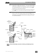
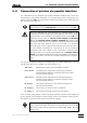
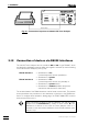
Fig. 24: Connection possibilities for the RS232 interfaces
3.12.1 Connection of a PC
IBM-compatible PCs are connected to the 746 VA Trace Analyzer via RS232 inter-
face 1 (”remote keyboard” function possible) or via RS232 interface 2 (”remote key-
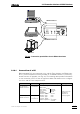
board” function not possible, see Fig. 24). The following table provides information
on the connection of PCs. It lists the required cables and details on the configura-
tion of the 746 VA Trace Analyzer and PC.
PC Cable
Settings on 746 VA Trace Analyzer
Settings on PC
PC with 25-pin
RS232 connector
6.2125.060
RS232 settings Ifc.1/2
Baud rate
Data bits Settings
Stop bit(s) same as
Parity on PC
Handshake
Receive mode on/off
setting of the RS
parameters
depends on
PC with 9-pin
RS232 connector
6.2125.060
+
6.2125.010
Balance type none
Printer type none
Printer width –
Remote keyboard off/send/
receive
control program
Printer
RS232 interface 1
RS232 interface 2
PC
Balance