757 VA Computrace Hardware Manual 8.757.1013 METROHM Ltd.
CH-9101 Herisau/Schweiz Internet www.metrohm.com E-Mail info@metrohm.ch 757 VA Computrace Hardware Manual 8.757.1013 14.09.
Table of contents Table of contents 1 Introduction ......................................................................................... 1 1.1 1.2 1.3 Instrument description...................................................................... 1 Information about the Instructions for Use....................................2 1.2.1 Organization ........................................................................... 2 1.2.2 Notation and pictograms ....................................................
Table of contents 3.9 Connection of the 813 Compact Autosampler ............................ 43 3.9.1 Electrical connection ............................................................ 43 3.9.2 Tubing connections.............................................................. 46 3.9.3 Software settings.................................................................. 48 3.9.4 Operation of the 813 Compact Autosampler ....................... 50 4 Safety.........................................................
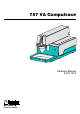
1.1 Instrument description 1 Introduction 1.1 Instrument description 757 VA Computrace is a PC-controlled system for voltammetry, which consists of the following parts: 1.757.0010 VA Computrace Stand with accessories 6.5326.000 VA Computrace Interface 6.2135.010 Connecting Cable 6.6032.100 VA Computrace Software 2.0 For a detailed description of the PC software «VA Computrace 2.0» see the 757 Software Manual.
1 Introduction 1.2 Information about the Instructions for Use Please read through these Instructions for Use carefully before you put the 757 VA Computrace Stand into operation. The Instructions for Use contain information and warnings to which the user must pay attention in order to assure safe operation of the instrument. 1.2.1 Organization These 8.757.
1.2 Information about the Instructions for Use 1.2.2 Notation and pictograms The following notations and pictograms (symbols) are used in these Instructions for Use: Mode 15 Parameter or entry value Part or control of 757 Hazard This symbol draws attention to a possible danger to life or of injury if the associated directions are not followed correctly. Warning This symbol draws attention to possible damage to instruments or instrument parts if the associated directions are not followed correctly.
1 Introduction 1.3 Support documentation 1.3.1 Application Bulletins The «Application Bulletin» is a collection of analytical methods, application examples and literature references. Of Metrohm's approximately 200 Application Bulletins, ca. 60 refer to Polarography and Voltammetry. All these Application Bulletins are available on request free of charge from your Metrohm supplier.
1.3 Support documentation No.
1 Introduction 1.3.2 No. Title 251 Polarographic determination of cinchocaine (dibucaine) in pharmaceutical preparations 254 Determination of zinc, cadmium, lead and copper by anodic stripping voltammetry using carbon electrodes 266 Voltammetric determination of titanium and uranium 276 Validation of Metrohm VA instruments using Standard Operating Procedures Application Notes The «Application Notes» present application information in concentrated form.
2 Parts and controls 2 Parts and controls In this section you will find the numbers and designations of the parts and controls of the 757 VA Computrace Stand. The numbering applies throughout the instructions for use, i.e. bold numbers in the text (e.g. 15) refer to the parts and controls illustrated here.
2 Parts and controls 1 2 3 4 5 6 7 Fig. 1: Front of the 757 VA Computrace Stand 8 1 Cover of measuring head arm hinged 5 Mains pilot lamp lit up when instrument switched on 2 Stopper (6.2709.080) to close the pipetting opening 6 Measuring vessel when measuring head arm is fully raised, the measuring vessel can be pulled forward out of the holder 3 3 Holder for measuring vessel 7 Drip pan (6.2711.040) 4 Gas wash bottle (6.2405.030) for inert gas supply (filling with dist.
2 Parts and controls 8 9 10 11 Type 1.757.0010 Nr. 100-240V f = 50-60Hz P = 26W ON 12 STANDBY 13 Remote PC Interface 14 Made by Metrohm Herisau Switzerland 15 Fig. 2: Rear of the 757 VA Computrace Stand 8 Connection for inert gas lead-off 12 Mains switch (on/off) on/off switching of instrument (the pilot lamp 5 is lit up when the instrument is on) 9 Connection for optional waste solution lead-off 13 Mains connection plug mains connection, see section 3.2.
2 Parts and controls 16 17 2 18 19 20 21 22 23 24 25 22 26 27 28 4 29 30 26 31 32 33 Fig. 3: Right side view of the 757 VA Computrace Stand (fully equipped) 34 35 36 37 16 38 17 2 39 19 20 50 49 48 47 46 31 45 44 43 28 42 39 25 41 40 Fig.
2 Parts and controls 2 Stopper (6.2709.080) to close the pipetting opening 27 Electrode cable ”RE” connection for reference electrode 22 4 Gas wash bottle (6.2405.030) for inert gas supply (must be filled halfway with dist. H2O, see section 3.2.5) 28 Drive belt (6.1244.020) connection between drive wheel 31 and drive shaft 24 29 PTFE tube (4.647.1350) for inert gas delivery to gas wash bottle 4 (attached) 30 FEP tubing (6.1805.
2 Parts and controls 12 42 Stirrer tip (6.1204.090) 43 PTFE tube (6.1819.010) for optional supply of the waste solution to gas wash bottle 44 (attached) 44 Gas wash bottle (6.2405.030) for separating mercury from the waste solution (attached) 45 PTFE tube (6.1819.
3.1 Setting up the instrument 3 Installation This section offers a full description of the 757 VA Computrace Stand and provides detailed information on the various electrodes and the stirrer. Reliable operation of the instrument is assured only if you follow the instructions in this section exactly. 3.1 Setting up the instrument 3.1.1 Packaging The 757 VA Computrace Stand is supplied together with the separately packed accessories in special packages designed to ensure excellent protection.
3 Installation 3.2 Installation of the 757 VA Computrace Stand If the 757 VA Computrace Stand is connected to the power supply, the instrument may not be opened or parts removed as there is a danger of contact with live components.
3.2 Installation of the 757 VA Computrace Stand 3.2.3 Connection to the PC The 757 VA Computrace Stand is connected to the PC via 6.2155.000 VA Computrace Interface. Proceed as follows: 1 Software installation • Switch on PC and start operating system (Windows™ 2000) without connection of the VA Computrace Interface via USB cable. • Insert installation CD into CD drive. • If the autorun option for the CD drive is disabled, select and Run. Browse for the Setup.
3 Installation 3.2.4 Equipping the measuring head The fixtures inserted in the openings and connections of the measuring head 20 in the 757 VA Computrace Stand depend on the working electrode selected (MME or DME) (see Fig. 6). The fully equipped measuring head for operation with a multimode electrode is illustrated in section 2 (Figs 3 and 4), that for operation with a rotating disk electrode in section 3.4 (Fig. 12).
3.2 Installation of the 757 VA Computrace Stand 51 52 53 20 54 55 19 56 57 58 59 60 61 62 63 64 65 66 67 Fig. 6: Measuring head arm 19 Measuring head arm 20 Measuring head 51 Opening for auxiliary electrode 39 (6.0343.000 Pt auxiliary electr. or optional GC electr. comprising 6.1241.020 Electrode holder and 6.1247.000 GC tip) 52 Threaded opening for dummy stopper 41 (6.1446.040) 53 Threaded opening for dummy stopper 40 (6.1446.
3 Installation 66 18 Threaded opening for FEP tubing 68 (6.1805.180); optional waste solution lead-off 67 Threaded opening for FEP tubing 34 (6.1805.090, already permanently attached); optional waste solution supply from gas wash bottle to waste 5 Install reference electrode • Insert reference electrode 22 in opening 58. • Attach electrode cable 27 (RE) to reference electrode 22: push cable lug under the screw and then tighten screw firmly.
3.2 Installation of the 757 VA Computrace Stand 3.2.5 Inert gas connection Nitrogen (N2) is generally used as the inert gas to deaerate the analyte solution and for operation of the MME. The nitrogen must be of sufficient purity. w(N2) ≥ 0.99996 (= 99.996%) for general polarography/voltammetry w(N2) ≥ 0.99999 (= 99.999% = "5 × 9") for analyses in organic solvents; for determinations involving very high current amplification (e.g.
3 Installation V2 33 V3 N2 V1 72 73 V4 4 50 Fig. 7: Scheme showing the inert gas connections at the 757 VA Computrace Stand 4 33 Gas wash bottle (6.2405.030) for inert gas supply (must be filled only halfway with dist. H2O or supporting electrolyte, see also Fig. 3) Slotted screw for controlling the inert gas flow for deaeration (see also Fig. 3) Note: The factory setting of ca.
3.3 Multi-mode electrode (MME) 3.3 Multi-mode electrode (MME) The multi-mode electrode combines the most important polarographic and voltammetric mercury electrodes in a single construction: 3.3.1 • HMDE Hanging mercury drop electrode Mercury is forced through a glass capillary until a drop forms at the capillary tip and the entire voltage sweep performed on this single stationary drop; in general with preceding enrichment (stripping voltammetry).
3 Installation 74 75 76 77 73 78 79 72 72 Connection for inert gas supply 73 Connection for inert gas supply (for all MME operating modes) 74 Locking ring (4.420.2920) for slotted screw 75 75 Slotted screw (6.1247.040) with PTFE membrane and built-in spring 76 Sealing needle (6.1247.020) 77 Screw thread for slotted screw 75 78 Unused connection 84 79 Screw thread for slotted screw 80 85 80 Slotted screw (4.420.
3.3 Multi-mode electrode (MME) 3.3.2 Filling the MME with mercury When handling mercury, it is necessary to take special precautionary measures. These are described in detail in section 4.2. All actions involving the electrode and mercury vessels must be performed in or over the drip pan 92 supplied (see Fig. 10). The Hg reservoir 82 of the multi-mode electrode 17 is filled with mercury of the highest degree of purity (mass fraction w ≥ 0.
3 Installation 2 Draw up mercury • Attach needle 91 to syringe 90. • Draw up 6 mL ultrapure mercury slowly and carefully using syringe 90. 3 Add mercury to MME • Lower syringe needle 91 into the top opening of the MME 17 between sealing ring 85 and sealing needle 76. • Expel mercury slowly and carefully from the syringe to allow it to flow into the Hg reservoir 82. The Hg reservoir 82 must never be filled more than 2/3 full with mercury. 3.3.
3.3 Multi-mode electrode (MME) 1 Install multi-mode electrode in 757 VA Computrace Stand • With the measuring head arm 19 tilted back, slide the empty measuring vessel 6 into the holder 3 of the 757 VA Computrace Stand and then lower the measuring head arm 19. • Carefully insert multi-mode electrode 17 in opening 55 of the measuring head 20 (during insertion, the tip of the capillary 88 must not touch the measuring head) and push in carefully as far as it will go.
3 Installation 5 Checking the MME for leaks • Switch on the dropping mercury electrode by selecting DME in the COMPUTRACE CONTROL window and clicking on drops freely out of the capillary. . The mercury • Select HMDE and click on . A single mercury drop is formed. Knock this off by gently tapping the MME 17 with your finger and check that the mercury flow has really stopped. Repeat this operation several times.
3.3 Multi-mode electrode (MME) 97 94 Pump 95 88 Vacuum release tap 17 92 96 93 96 Fig. 10: Setting up the filling station Vacuum 94 Vacuum 95 1 2 88 3 92 93 17 Fig. 11: Filling the capillary 17 Multi-mode electrode (6.1246.0020) 94 Filling tubing (6.1817.000) 88 Glass capillary (6.1226.030) 95 Filling cone (4.420.2860) (part of the filling tubing 94) 92 Drip pan (6.2711.030) 96 Gas wash bottle 93 Electrode holder (6.2615.030) 97 Tubing coupling (6.1809.
3 Installation 5 Evacuating in vertical position • Place multi-mode electrode 17 vertically in the electrode holder 93 (see Fig. 11-1). • Evacuate for ca. 2 min in this position. 6 Evacuating in inclined position • Carefully tilt multi-mode electrode 17 in the electrode holder 93 to an inclined position and continue evacuating (see Fig. 11-2).
3.3 Multi-mode electrode (MME) 10 Pressurize the MME • Switch on 757 VA Computrace Stand with mains switch 12 (the 757 VA Computrace Stand must first be installed properly as described in section 3.2). • Start the VA Computrace program and click on or MAIN WINDOW / Utility / Computrace control to open the COMPUTRACE CONTROL window. Then switch on the inert gas supply to the 757 VA Computrace Stand by clicking on DME.
3 Installation 3.3.6 Storing the MME On completion of the measurements, the MME is stored in the 757 VA Computrace Stand so that the tip of the glass capillary 88 is immersed in pure water (or in the solvent used). This prevents blockage of the capillary by crystallized salts. An electrode treated in this manner can be taken out of the 757 VA Computrace Stand after a few hours and stored in air for a lengthy period without suffering any damage.
3.3 Multi-mode electrode (MME) 3.3.8 Changing the capillary Contamination of the glass capillary can necessitate its replacement. In such a case, proceed as follows: 1 Remove multi-mode electrode from 757 VA Computrace Stand • Unscrew FEP tubing 30 and 38 from the MME, disconnect electrode cable 16 from MME. • Take multi-mode electrode 17 out of measuring head 20 while gently tapping the MME to knock off any mercury drops on the glass capillary into the measuring vessel.
3 Installation 3.3.9 Cleaning the MME If the mercury in the multi-mode electrode is contaminated and this leads to disturbances, the MME must be cleaned and refilled with ultrapure mercury. Proceed as follows: 1 Remove multi-mode electrode from 757 VA Computrace Stand • Unscrew FEP tubing 30 and 38 from the MME, disconnect electrode cable 16 from MME.
3.3 Multi-mode electrode (MME) 6 Replace sealing needle 76 if need be If problems with leaks arise owing to a worn, deformed or damaged sealing needle 76, this must be replaced. Three spare needles are supplied separately in a protective plastic package. After unpacking a needle, please avoid any contact whatsoever with the needle tip. The spare needle 76 is installed as follows: • Carefully pull old sealing needle 76 out of PTFE membrane of the slotted screw 75.
3 Installation 3.4 Rotating disk electrode (RDE) The rotating disk electrode (RDE) is available as an option and can be used in place of the MME in the 757 VA Computrace Stand with different electrode tips as a working electrode. The following accessories have to be ordered (see also section 6.2): • 6.1246.000 • 6.1204.XXX • 6.2709.040 • 6.2802.000 • 6.2827.000 Drive shaft for rotating electrode Electrode tip for rotating electrode 6.1204.100 Ultra Trace Graphite 6.1204.110 GC (Glassy Carbon) 6.1204.
3.4 Rotating disk electrode (RDE) 34 35 36 37 16 30 98 2 39 19 20 31 28 38 100 99 39 Fig. 12: Measuring head arm with rotating disk electrode (RDE) 2 Stopper (6.2709.080) to close the pipetting opening 36 FEP tubing (6.1805.180) for inert gas supply to tapping mechanism (attached) 16 Electrode cable ”WE” connection for working electr.
3 Installation 3.5 Reference electrode 3.5.1 Construction The complete reference electrode (RE) 22 comprises two parts: • 6.0728.0X0 Ag/AgCl reference system (101) with ceramic diaphragm type D, diameter = 1 mm 6.0728.020 Reference system: Ag/AgCl/c(KCl) = 3 mol/L; supplied in a holder filled with c(KCl) = 3 mol/L as standard 6.0728.010 Reference system: Ag/AgCl supplied dry (option) • 6.1245.
3.5 Reference electrode 3.5.2 Startup procedure The reference electrode 22 is supplied in modular form as the reference system 101 and the electrolyte vessel 102 and has first to be filled and assembled as follows: 1 Add internal electrolyte Filling of the reference system is necessary only when the optional 6.0728.010 Reference system supplied dry is used, if the internal electrolyte solution has to be renewed or if gas bubbles interrupt the electrical connection.
3 Installation 3.6 Auxiliary electrode 3.6.1 Construction The following electrodes can be used as the auxiliary electrode 39 (AE): • 6.0343.000 Pt auxiliary electrode supplied as standard • 6.1241.020 6.1247.000 Electrode holder and Glassy carbon tip together form the glassy carbon auxiliary electrode available as an option The construction of the two auxiliary electrodes and the designations of the individual parts are shown in Fig. 14. 3.6.2 Startup procedure The 6.0343.
3.7 Stirrer 39 112 39 112 Electrical connection for cable "AE" 113 Pt Auxiliary electrode (6.0343.000) 114 Pt tip (permanently attached) 115 Electrode holder (6.1241.020) 116 Locking ring 117 Glassy carbon tip (6.1247.000) 112 115 113 116 117 114 Auxiliary electrode Fig. 14: Construction of the auxiliary electrode 3.7 Stirrer The complete stirrer comprises two parts (see also Fig. 4): • 6.1246.010 Drive shaft (24) • 6.1204.
3 Installation 3.8 Connection of 765 Dosimats The predecessor model 665 Dosimat can also be connected instead of the 765 Dosimat. Up to five 765 Dosimats can be attached to the 757 VA Computrace Stand for the automatic addition of standard and auxiliary solutions. For the connection of 1 or 2 Dosimats, the 6.2141.080 Cable is used, for the connection of up to 5 Dosimats, the 6.9921.170 cable. The 765 Dosimat and the accessories needed have the following ordering designations (see also section 6.2): • 2.
3.8 Connection of 765 Dosimats 3.8.2 Tubing connection For the addition of standard or auxiliary solutions into the measuring vessel of the 757 VA Computrace Stand the 4-way microtip 26 (6.1824.000) can be used. It is fitted with 4 lengths of PTFE tubing with connection nipples for direct attachment to the Exchange unit of the 765 Dosimat. To ready the 765 Dosimat for automatic dispensing, proceed as follows: 1 Mount Exchange unit on 765 Dosimat • Procedure, see section 5 of 765 Instructions for Use.
3 Installation 3.8.3 Changing the Exchange unit The Exchange unit mounted on the 765 Dosimat can be changed only in the exchange position which is reached after filling. Please proceed as follows: 1 Fill exchange unit At the start of the VA Computrace program, the exchange unit is automatically filled. So this step is only necessary if the Dosimat has already been used during the running program session. • Click on or MAIN WINDOW / Utility / Dosimat control to open the DOSIwindow.
3.9 Connection of the 813 Compact Autosampler 3.9 Connection of the 813 Compact Autosampler With the 813 Compact Autosampler connected to the 757 VA Computrace Stand, max. 18 samples can be transferred to the measuring vessel at the 757 VA Computrace Stand. After each measurement, the measuring vessel is rinsed by means of two 772 Pump Units connected to a 731 Relay Box.
3 Installation 6.2141.080 Cable 731 772 772 765 757 813 6.2141.150 Cable Fig. 15: Electrical connection of the 813 Compact Autosampler 6.1831.050 6.1826.100 2 20 -24 0 V I 6.1829.020 O 2x6.1820.020 1 00 -12 0 V Rinsing solution 772 FUSES/EMPL OYER USE ONL Y WITH 2 50 V 6.1618.050 2x6.1820.050 DES FUSIBL ES DE 25 0 V UNIQUEM ENT AVEC 6.1602.105 6.1805.530 6.1822.410 Rinsing pump 2x6.1808.000 6.1805.530 6.1602.105 6.1805.020 6.1805.180 6.1805.530 Aspiration pump 6.1618.050 Waste 6.
3.9 Connection of the 813 Compact Autosampler 34 118 119 20 2 cm 2 cm 3 cm 120 121 45 43 44 Fig. 17: Installation of accessories for rinsing and siphoning off 19 Measuring head arm 20 Measuring head 34 118 FEP tubing (6.1805.180) for transferring the waste solution to gas wash bottle 44 FEP tubing (6.1805.100) for waste solution lead-off (attached) 119 FEP tubing (6.1805.100) for supply of the rinsing solution 43 PTFE tube (6.1819.
3 Installation 3.9.2 Tubing connections For operation of the 757 VA Computrace Stand with 813 Compact Autosampler and 772 Pump Units, the accessories and tubing connections must be installed according to Fig. 16. Proceed as follows: 1 Install accessories at 757 VA Computrace Stand • Instead of the 6.1415.210 measuring vessel, install the 6.1456.210 measuring vessel at the 757 VA Computrace Stand. • Cut PFTE tube 43 (6.1819.010) inserted in opening 67 of the measuring head 20 to a length of max.
3.9 Connection of the 813 Compact Autosampler 3 Connect 772 siphoning pump • Cut 6.1826.100 pump tubing to a length of ca. 17 cm. • Attach two 6.1820.050 tubing connectors to both ends of the 6.1826.100 pump tubing and install it at the first 772 Pump Unit (see Instructions for Use 772). • Screw a 6.1820.020 thread onto both 6.1820.050 connectors. • Using a 6.1805.530 FEP tubing, connect the lower end of the pump tubing on the siphoning pump to the 6.1808.
3 Installation 3.9.3 Software settings Before putting into operation the 757 VA Computrace Stand with the 813 Compact Autosampler, the following settings have to be made in the "757 VA Computrace 2.0" software program: 1 Set Dosimat parameters • Click on MAIN WINDOW / Settings / General settings and select the Hardware tab. • For each Dosimat connected to the remote interface of the 757 VA Computrace Stand, check the Dosimat no.
3.9 Connection of the 813 Compact Autosampler 2 Set automation parameters • Click on MAIN WINDOW / Settings / General settings and select the Automation tab. • Enable the Use Autosampler option, modify the automation parameters as desired and close the GENERAL SETTINGS window. • Close the "757 VA Computrace 2.0" program and restart it. 3 Test automation parameters • Fill two sample vessels with water and place them one after the other on the sample rack of the 813 Compact Autosampler.
3 Installation 3.9.4 Operation of the 813 Compact Autosampler After installation of the instruments according to sections 3.9.1...3.9.3 sample series using the 813 Compact Autosampler can be started. Proceed always in the following sequence: 1 Switch on instruments • Switch on Dosimats and 757 VA Computrace Stand. • Switch on 813 Compact Autosampler and 731 Relay Box. • Switch on PC. • Start 757 VA Computrace software (see Software Manual, section 2.2).
4.1 Electrical safety 4 Safety 4.1 Electrical safety While electrical safety in the handling of the 757 VA Computrace Stand is assured in the context of the specifications IEC 61010-1 (protection class 1), the following points should be noted: • Mains connection Setting mains connection must be effected in accordance with the instructions in section 3.2.1.
4 Safety 4.2 Safety considerations concerning mercury 4.2.1 Properties of mercury The most important properties of mercury (Hg) are listed in the Table below. This compilation allows the following summary: • Mercury is a heavy metal with a very high density and is liquid at room temperature. • Mercury is mobile at room temperature and tends to form drops because of its high surface tension. The surface tension is around 6 times greater than that of water, Hg is thus not wetted by water.
4.2 Safety considerations concerning mercury 4.2.2 Toxicity of mercury and its compounds Mercury and its compounds are toxic since they react with enzymes containing sulfur and decompose them with the formation of HgS. The toxicity depends on the chemical and physical state of the mercury [4, 8 – 10]: • Metallic liquid mercury is readily resorbed by the skin and finds its way through glandular passages into lower skin regions where it is oxidized and carried on as a salt.
4 Safety • Trapping of mercury drops Single mercury drops in this drip pan or any other spilt mercury can be bound in a simple manner by amalgamation: − with silver (Ag): Metrohm drop catcher Type 6.2406.000 which is included in the standard outfit of the 757 VA Computrace Stand − with tin (Sn): e.g. the thin tin foil supplied by Merck, Darmstadt/FRG − with special laboratory aids: e.g. Mercurisorb-Roth from Roth, Karlsruhe/FRG; e.g. Mercury Sponge and Resisorb from Baker, Phillipsburg, N.J.
4.2 Safety considerations concerning mercury 4.2.4 References dealing with mercury [1] [2] [3] [4] [5] [6] [7] [8] [9] [10] [11] [12] [13] [14] [15] [16] Documenta Geigy Wissenschaftliche Tabellen, 7. Ausgabe, Seite 210 (”Masseinheiten, Dichte”), Georg Thieme Verlag, Stuttgart (BRD), 1975 Berufsgenossenschaft der chemischen Industrie (Herausgeber) Quecksilber und seine Verbindungen Merkblatt, Seite 3...4, Verlag Chemie, Weinheim (BRD), 1980 Synowietz, C.; Schä fer, K.
4 Safety 56 757 VA Computrace – Hardware
5 Technical data 5 Technical data Subject to changes ! The listed technical data apply to an ambient temperature of 25°C. Brief characterization PC-controlled system for voltammetry, set chemical workplace with potentiostat and measuring amplifier. With multi-mode electrode, rotating disk electrode (RDE) as option. Tilt-back measuring arm, integrated drip pan. Current measurement techniques DC NP DP SQW AC1 AC2 PSA CV Direct Current Normal Pulse Differential Pulse Square Wave (10 ...
5 Technical data Sweep rate Pulse amplitudes with voltage step 10 mV CV: 0 … 30 V/s DP, NP: 0 … 0.5 V/s AC1, AC2: DP, NP: SQW: SQW, DC: 0 … 20 V/s AC1, AC2: 0 … 0.02 V/s 1 mV … 1 V –1 … 1 V 0.15 mV … 1 V Current measurement Current ranges 100 nA … 10 mA in 6 ranges Current resolution 0.5 % of the current range Minimum current Imin 5 pA Maximum current Imax 35 mA Integration times 0.1 … 20 ms Multi-mode electrode MME (working electrode WE) Designation 6.1246.
5 Technical data Auxiliary electrode (AE) Pt auxiliary electrode GC auxiliary electrode (option) 6.0343.000 Platinum electrode 6.1241.020 Electrode holder + 6.1247.000 Glassy carbon tip Stirrer Construction Material Rotational speed Speed constancy 6.1246.010 Drive shaft + screw-on 6.1204.090 Stirrer tip PTFE 200, 400, 600, ... , 3000 min–1 ±5% Measuring vessels 6.1415.210 6.1415.150 6.1418.220 6.1450.210 6.1456.210 6.1457.210 standard measuring vessel made of glass; working volume = 10 ...
5 Technical data VA Computrace Interface Designation 6.2155.000 VA Computrace Interface Type Interface USB – VA Computrace Stand Plug to 757 D-Sub with 37 pins Mains connection Voltage 100...240 V Frequency 50...60 Hz Power consumption 26 W Fuse 2 × 1.0 ATH (to be replaced by Metrohm Service only using the same type). Additional electronic overload protection.
6.1 Scope of delivery 6 Appendix Subject to changes! All dimensions are given in mm. 6.1 Scope of delivery 6.1.1 2.757.0110 VA Computrace The 2.757.0110 VA Computrace System includes the following accessories: Quant. Order No. Description 1 1.757.0010 757 VA Computrace Stand Instrument without accessories 1 6.0343.000 Pt Auxiliary electrode 116 11 1 6.0728.020 11 Ag/AgCl reference system with ceramic diaphragm Ag/AgCl/c(KCl) = 3 mol/L Together with the 6.1245.
6 Appendix Quant. Order No. Description 1 6.1226.030 Glass capillaries for 6.1246.020 Multi-mode electrode 116 Set of 10 incl. two 4.420.2800 sealing rings 1 6.1244.020 Drive belt made of EPDM (ethylene propylene rubber), set of 3 Connection motor – drive shaft (6.1246.010 or 6.1246.000) 1 6.1245.010 15 Electrolyte vessel with ceramic diaphragm B-NS 14/15 Together with the 6.0728.
6.1 Scope of delivery Quant. Order No. Description 1 6.1415.210 Measuring vessel clear glass ∅78 Volume: 10 ... 90 mL 80 ∅23 7 6.1446.040 Dummy stopper made of PVDF, with M6 thread ∅4.9 For closing the unused openings in the measuring vessel upper half 21.5 1 6.1801.080 PVC tubing for supply of the inert gas 7 4 Length L = 4 m 4 6.1808.000 Tubing coupling made of ETFE, with 2 M6 threads For the connection of 2 lengths of tubing with thread M6 (e.g. 6.1805.XXX) 1 6.1817.
6 Appendix Quant. Order No. Description 1 6.2301.100 Lead standard solution ρ(Pb2+) = 1.000 ± 0.003 g/L plastic bottle, volume V = 50 mL To perform the test methods. 1 6.2308.020 KCl electrolyte solution c(KCl) = 3 mol/L plastic bottle, volume V = 250 mL For 6.0728.020/6.1245.010 Ag/AgCl reference electrode 1 6.2406.000 Mercury drop catcher silver wire in plastic bottle For the destruction of mercury drops by amalgamation 1 6.2615.
6.1 Scope of delivery Quant. Order No. Description 1 6.2711.040 Drip pan made of PS (polystyrene) 20 To be inserted in the 757 VA Computrace Stand 150 200 1 6.2730.030 Stopper with nipple and O-ring For closing the opening of the 757 VA Computrace Stand when the 6.1824.000 4-way microtip is not used (inserted in opening 59) 1 6.2739.000 Spanner for screwing down plastic nipples 38 ∅10 ∅8 68 1 6.2816.
6 Appendix 6.1.2 2.757.0120 VA Computrace The 2.757.0120 VA Computrace System includes the following accessories: Quant. Order No. Description 1 1.757.0010 757 VA Computrace Stand Instrument without accessories 7 6.1446.040 Dummy stopper made of PVDF, with M6 thread ∅4.9 For closing the unused openings in the measuring vessel upper half 21.5 1 6.1801.080 PVC tubing for supply of the inert gas 7 4 Length L = 4 m 4 6.1808.
6.1 Scope of delivery Quant. Order No. Description 1 6.2709.080 Stopper 18 For closing the pipetting aperture of the 757 VA Computrace Stand 1 6.2711.040 76 Drip pan made of PS (polystyrene) 20 To be inserted in the 757 VA Computrace Stand 150 200 1 6.2730.030 Stopper with nipple and O-ring For closing the opening of the 757 VA Computrace Stand when the 6.1824.000 4-way microtip is not used (inserted in opening 59) 1 6.2739.
6 Appendix 6.2 Options Order No. Description 6.0728.010 Ag/AgCl reference system with ceramic diaphragm 11 Together with the 6.1245.010 Electrolyte vessel forms a complete reference electrode (double-junction construction, assembly, see section 3.5.2). 116 The Ag/AgCl reference system is supplied with an empty holder screwed on; the holder can be filled with the desired reference electrolyte. 6.1204.XXX M3 Electrode tip Together with the 6.1246.000 Drive shaft forms the stirrer.
6.2 Options Order No. Description 6.1247.000 Glassy carbon tip 65 ∅2 Together with the 6.1241.020 electrode holder forms the GC auxiliary electrode. 6.1247.040 Slotted screw 20 Slotted screw 75 with holding sleeve. 33 6.1415.150 ∅78 Measuring vessel clear glass, incl. 6.2036.000 holding ring 80 Volume: 5 ... 70 mL ∅23 6.1418.220 ∅78 Measuring vessel clear glass, with thermostatic jacket; incl. 6.2036.000 holding ring Volume: 12 ... 70 mL 82 ∅30 6.1450.
6 Appendix Order No. Description 6.2827.000 Trimming tool for regeneration of the 6.1204.100 Ultra Trace Graphite electrode 53 49 2.765.0010 765 Dosimat Dispensing unit for 757 VA Computrace Stand. 6.3014.XXX Exchange unit with standard reagent bottle of brown glass, rectangular, volume V = 1 L, with GL 45 ISO/DIN glass thread; burette cylinder of clear glass with light protector; PCTFE/PTFE flat stopcock 6.3014.153 burette volume V = 6.3014.213 burette volume V = 10 mL 6.3014.
6.3 Warranty 6.3 Warranty The warranty on our products is limited to defects that are traceable to material, construction or manufacturing error, which occur within 12 months from the day of delivery. In this case, the defects will be rectified in our workshops free of charge. Transport costs are to be paid by the customer. For day and night operation, the warranty is limited to 6 months. Glass breakage in the case of electrodes or other parts is not covered by the warranty.
6 Appendix 6.4 EU Declaration of conformity EU Declaration of Conformity The METROHM AG company, Herisau, Switzerland hereby certifies, that the instrument: 757 VA Computrace meets the requirements of EC Directives 89/336/EWG and 73/23/EWG.
6.5 Certificate of conformity and system validation 6.5 Certificate of conformity and system validation Certificate of Conformity and System Validation This is to certify the conformity to the standard specifications for electrical appliances and accessories, as well as to the standard specifications for security and to system validation issued by the manufacturing company. Name of commodity: 757 VA Computrace Name of manufacturer: Metrohm Ltd.
6 Appendix 6.6 Index A Ag electrode tip (6.1204.130) ................................34,68 Ag/AgCl filling 105 Figure ......................................................................36 Ag/AgCl reference system.......... see Reference system Ambient temperature..................................................60 Appendix.....................................................................61 Application Bulletins .....................................................4 Application Notes ..............
6.6 Index Installing the drive belt ............................................16 Ordering designation ..............................................62 Drive shaft 100 (6.1246.000) Construction of RDE ...............................................34 Figure ......................................................................35 Insertion in measuring head....................................16 Ordering designation ..............................................68 Drive wheel 31 Figure ......................
6 Appendix H Handling of mercury ...................................................53 Hazard ..........................................................................3 Height .........................................................................60 HMDE .........................................................................21 Holder 3 for measuring vessel Figure ........................................................................8 Installation of measuring vessel..............................
6.6 Index O Opening 51 Figure ......................................................................17 Insertion of auxiliary electrode............................18,38 Opening 52 Insertion of stopper 41............................................16 Opening 53 Insertion of stopper 40............................................16 Opening 55 Figure ......................................................................17 Inserting stopper 98 ................................................
6 Appendix Serial number 11 Figure ........................................................................9 Setting up filling station ..............................................27 Setting up instrument .................................................13 Slotted screw 33 Figure ......................................................................11 Inert gas connection scheme .................................20 Slotted screw 50 Figure ....................................................................