CH-9101 Herisau/Switzerland E-Mail info@metrohm.com Internet www.metrohm.com 767 Calibrated Reference for mV, pH, S, :S, °C Instructions for Use 8.767.1023 08.
Teachware Metrohm AG Oberdorfstrasse 68 CH-9101 Herisau teachware@metrohm.com These instructions are protected by copyright. All rights reserved. Although all the information given in these instructions has been checked with great care, errors cannot be entirely excluded. Should you notice any mistakes please inform the author at the address given above.
Contents Table of contents 1 Overview ............................................................... 1 1.1 Introduction ....................................................................................................1 1.2 Functional description ...................................................................................2 2 General instrument handling............................... 4 2.1 Storage ................................................................................................
Contents List of illustrations Fig. 1: 767 Calibrated Reference...............................................................................................1 Fig. 2 Functional scheme: Position "Voltage source ON" .........................................................1 Fig. 3: Label on cover ................................................................................................................1 Fig. 4: Unloaded potential source ..................................................................
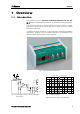
1 Overview 1 Overview 1.1 Introduction The measuring source 767.0010 Calibrated Reference for mV, pH, Ω, µS, °C is a calibrated instrument for the quantities mentioned above. It is connected instead of the electrodes and can be used for rapidly and easily checking of the functioning and the basic accuracy of most Metrohm instruments.
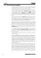
1 Overview 1.2 Functional description As mentioned before the input resistance of high-impedance measuring amplifiers (pH Meters, Titrators) and, for separate amplifiers, the insulation of the reference point from the earth can be checked. This is done using the potential of a reference diode (approx. 1200 mV) on the one hand at output socket (5) +U/direct and on the other hand a high-impedance resistor (1 GΩ) at socket (4) +U/1 GΩ. This potential is also switched to socket (6) −U÷/direct by a divider.
1 Overview Metrohm electrodes and means that a test can be carried out very easily: Screw off cable at electrode plug-in head → plug into Calibrated Reference → measure If this check produces a variation from the expected result then it is not immediately clear as to whether the error lies in the instrument to be checked or in the cable.
2 General instrument handling 2 General instrument handling 2.1 Storage It is best to store the Calibrated Reference in its own case (with closed cover) together with its accessory cables. In this way it is protected against dirt, mechanical stress and moisture. 2.2 Maintenance The instrument needs no real maintenance (it also contains no batteries). Finger prints or other dirt on the solar cell should be removed with a cloth which has been slightly moistened with window-cleaning liquid or alcohol.
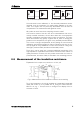
2 General instrument handling Ri Ri Rinput E E Fig. 4: Unloaded potential source Rx Rinput Fig. 5: On-load potential source If the electrode is now calibrated, i.e. the electrode parameters are determined, then the instrument is in reality being adapted to the electrode. This means that the previously determined error will also be compensated. The measurement will again be correct.
3 Procedure for checking instruments 3 Procedure for checking instruments 3.1 Basics The 767 Calibrated Reference is connected instead of the sensors, if possible by means of the original sensor cable. If this is not possible (e.g. for electrodes without a plug-in head) a list of suitable cables can be found in the appendix, see chap. 5.2. Each instrument can be checked with the Calibrated Reference within the normal operating program and therefore also with the worked-out methods.
3 Procedure for checking instruments 3.2.1 1. U/mV, pH carry out on instrument or sensor: carry out on Calibrated Reference: screw off cable at sensor (for plug-in head electrodes, otherwise use corresponding accessory cable, see chap. 5.2 close cover 2. 3. compare display with: remarks place sensor in storage tube connect sensor cable to socket (5) measure mV mV value (5) 4. open cover 5. connect sensor cable to socket (4) 6.
3 Procedure for checking instruments 3.2.2 1. Polarization current and voltage source carry out on instrument or sensor: carry out on Calibrated Reference: screw off cable at sensor close cover 2. 3.
3 Procedure for checking instruments 3.2.4 Tolerances Instruments with digital display: Potential U ± 1 mV pH value ± 0.02 Temperature ± 0.5 °C Polarization functionality test Instruments with analog display: The tolerance is within the reading accuracy. Example: Theoretical potential value: 1200.7 mV Instrument resolution: 1 mV, i.e. nominal pot. value =1201 mV. The test is OK when the read off value lies between 1200...1202 mV.
3 Procedure for checking instruments 3.3.2 Temperature Checking the temperature, see chapter 3.2.3. Note During the measurement the two Pt 100 / Pt 1000 resistances at sockets (1)....(3) can also be used at the same time as the conductance measurement (see further up). Please note that the measuring temperature of the instrument to be tested is approx. 0°C, while the information in the table refers to 20°C. This must be converted accordingly.
3 Procedure for checking instruments 3. note following parameters, then set (example 679) : temperature (see above) 50°C cond. range 20 µS/cm paper feed 20 cm/h 4. press start 5. 6. wait until the printer is printing out a channel which has not been checked. Replug cable (see Fig. 8, p. 11), so that 14.3 kΩ ≅ approx. 69 µS is obtained (see G value (5)) see G value for Rancimat in certificate for 767.0010 (approx.
4 Checking by means of the diagnosis instructions 4 Checking by means of the diagnosis instructions For most Metrohm instruments the so-called diagnosis instructions can be found in the Instructions for Use. These are intended to provide the possibility of testing an instrument with real or suspected malfunctions in a simple way.
5 Appendix 5 Appendix 5.1 5.1.1 Technical specifications Measuring source 3 outputs with socket G: socket (4) socket (5) socket (6) cover closed voltage 0 mV 0 mV 0 mV (pH = 7) resistance 1 GS 14.3 kS 460 kS cover open voltage approx. 1200 mV approx. 1200 mV approx. - 341 mV (pH = 12.7) Outputs with sockets B (temperature measurement): socket (1) socket (2) socket (3) 100 S (Pt100) 1000 S (Pt 1000) The individual data are given in the two tables on the cover.
5 Appendix 5.1.4 Ambient temperature Nominal working range Storage Transport 5.1.5 5 ... 40 °C – 20 ... 60 °C – 40 ... 60 °C Safety specifications Construction and testing 5.1.6 according to IEC publication 1010, protection class 3 Electricity supply Solar cells (no batteries) 5.1.7 5.2 Dimensions Width Height Depth 125 mm 45 mm 85 mm Weight Weight (with accessories) approx. 350 g approx. 1 kg Cables for connecting 767 – instrument X Please note that the cables in the 767.
5 Appendix ordering number of original cable 6.2104.020 6.2104.050 6.2104.080 2x 6.2106.020 with ID 6.2150.040 6.2150.030 6.2150.020 2x 6.2150.000 6.2150.010 Titrators 526 536 X X 576 X 636, 670 672, 682, 686 X 702, 716, 718, 719, 720, 721, 726, 736, 751, 785 X X X X X X X X X KF instruments 678 684, 701, 737, 758, 784 707, 768 X Rancimat 617, 679 X With newer instruments you can normally use the cables 6.2150.040 (pH/mV measurement) and 6.2150.000 (temperature measurement). 5.
5 Appendix 5.4 5.4.1 Warranty and conformity Warranty The warranty on our products is limited to defects that are traceable to material, construction or manufacturing error which occur within 12 months from the day of delivery. In this case the defects will be rectified in our workshops free of charge. Transport costs are to be paid by the customer. For day and night operation the warranty is limited to 6 months. Glass breakage in the case of electrodes or other parts is not covered by the warranty.
5 Appendix 5.4.2 Declaration of Conformity This is to certify the conformity to the standard specifications for electrical appliances and accessories, as well as to the standard specifications for security and to system validation issued by the manufacturing company. Name of commodity 767 Calibrated Reference Description CH-9101 Herisau/Switzerland E-Mail info@metrohm.com www.metrohm.com Instrument for verification of measured values: tension U/mV, pH, resistance, temperature, conductance.
5 Appendix 5.4.3 Quality Management Principles Metrohm Ltd., CH-9101 Herisau, Switzerland CH-9101 Herisau/Switzerland E-Mail info@metrohm.com Internet www.metrohm.com Metrohm Ltd. holds the ISO 9001 Certificate, registration number 10872-02, issued by SQS (Swiss Association for Quality and Management Systems). Internal and external audits are carried out periodically to assure that the standards defined by Metrohm’s QM Manual are maintained.
6 Index 6 Index A Ambient temperature ..............14 C Cable.......................................14 Calibration 767...................................4 Electrode .....................5, 7 Cleaning Solar cell ..........................4 Conductivity meter................2, 9 Conductometer.......................14 Connecting cable....................14 Cover ....................................2, 4 D Depth ......................................14 Dimensions .............................