Metrohm AG CH-9101 Herisau (Switzerland) KF Oven 768 Series 01... ! The following parts around the heating tube of the KF Oven can become hot: Heating tube, lateral shielding walls of the heating tube, guard grill of the heating tube, jacket of the outlet heating. Caution: Never touch these parts and ensure they never come into contact with solvents! 98.12 Ti 8.768.
Inhalt Inhaltsverzeichnis 1. Introduction ...................................................................................................................... 1 1.1 Overview....................................................................................................................... 1 1.2 Operating principle........................................................................................................ 4 2. Operating conditions ............................................................
Inhalt 6. Appendix......................................................................................................................... 53 6.1 Technical specifications .............................................................................................. 53 6.2 "Remote" socket ......................................................................................................... 54 6.2.2 Status of the lines during the automatic determination.......................................... 55 6.
1.1 Overview 1. Introduction 1.
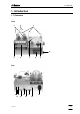
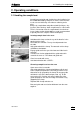
Front 2 1 Drying flasks filled with molecular sieves. For drying the carrier gas. 2 Tubing connections with 6.1805.180 Tubing. 3 Tubing connections with 6.1805.080 Tubing. 4 Adjustment for gas flow 5 Oven insert tube contains sample boat with guide rod. 6 Control panel with display, keypad and status lamps. 7 Temperature sensor for measuring the sample temperature. 8 Heating tube with lateral shielding walls and guard grill. 9 Outlet tubing leads into titration vessel. 6.1805.
Rear 768 KF Oven 10 Tubing connection with 6.1805.040 Tubing. 11 Contrast adjustment for the display 12 Dust filter 13 Connection for titrators 14 Connection for temperature sensor plug the grey connector of the cable into the red socket of the KF Oven! 15 Connection for outlet heating 16 RS232 interface for connection of a printer or computer. 17 Model plate with manufacturing, serial and instrument number. Display of the set mains voltage, the mains frequency and the power consumption.
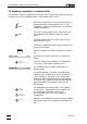
1.2 Operating principle 1.2 Operating principle Operating scheme: Sample temp. Magnet Sample boat Drying flasks with molecular sieves Heater glass Valve to "PURGE" Valve to "TRANSFER" Moves sample boat To KF titration cell To Oven Purge To Oven Air/N2 in From Oven Valve Measurement of the gas flow Setting the gas flow Air out Air pump Air filter Interior of the oven Gas flow If air is used as the carrier gas, work is carried out with the air pump built into the oven.
2.1 Handling the sample boat 2. Operating conditions 2.1 Handling the sample boat Sample boat and guide rod should always be handled using the 6.2056.000 Holding Clamp to ensure the measurement results are not falsified by skin moisture adhering to the glass. Always dry sample boat and guide rod well (hair dryer, drying oven) after cleaning. Store sample boats in a desiccator. There is no need to clean the sample boat if the aluminum inserts (order number 6.2623.
2.2 Automatic sequence of a determination 2.2 Automatic sequence of a determination The automatic sequence facilitates the work when a KF Titrator is attached. After the start, all steps necessary for the determination are performed at the KF Oven. After being switching on, the oven heats up to the set temperature (when "auto preparation: on" is set in ). Until the set temperature is reached, the "READY" lamp flashes.
2.3 Settings on KF Oven 2.3 Settings on KF Oven 2.3.1 Keypad HEATER PUMP 7 8 9 VALVE PUMP 5 6 4 READY BOAT IN 1 BOAT OUT 2 3 . – PRINT 0 PURGE VALVE TRANSFER SELECT CLEAR CONFIG STOP QUIT ENTER PARAM START PUMP HEATER Keys for individual manual functions Switches heating off/on. The "HEATER" lamp lights up or flashes when the heating is switched on. (The lamp is on continuously when full heating power is used; it flashes with reduced heating power.
2.3 Settings on KF Oven Input and determination control keys
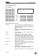
2.3 Settings on KF Oven 2.3.2 key The inquiries are divided into groups. The titles of the inquiry groups are marked with the ">" character. Entry into the inquiry group with . CONFIG >oven settings auto preparation: valve control: Inquiry group: General oven settings OFF Automatic preparation after switching on (ON, OFF) "ON " means: Automatic heating to the sample temperature.
2.3 Settings on KF Oven >auxiliaries dialog: Inquiry group: Auxiliaries english run number 0 auto start OFF Automatic, internal apparatus start (1...9999, OFF) Number of automatic starts. start delay 0 s Start delay (0...9999 s) Delay time following the start before the automatic determination begins. The wait time can be aborted with . beeper 1 device label program baud rate: Current run number (0...9999) The run number is set to 0 when the oven is switched on. Audio signal (1...
2.3 Settings on KF Oven 2.3.3 key Contains the parameters for the automatic determination. *live means: These parameters can be edited during the automatic determination. PARAM temperature unit gas flow: min.gas flow gas type: purge time 50 °C mL/min 5 mL/min Minimum gas flow (0...999 mL/h or 0...59.9 L/h) The automatic determination can be started only when the set minimum gas flow has been reached.
2.3 Settings on KF Oven 2.3.4 Special settings CONFIG Switch the Oven OFF. Press key , keep key pressed and switch the Oven ON again.
2.4 Practical tips 2.4 Practical tips Sample introduction via top opening of the insert tube This possibility can be used if several samples can be heated in succession in the same sample boat. Add samples to sample boat with a syringe or open screw cover. Selection of the carrier gas N2 should always be used as the carrier gas when the hot sample is sensitive to air or oxygen and evolves substances which interfere with the KF reaction.
2.
3.1 General rules 3. Operation via RS232 interface 3.1 General rules The 768 KF Oven has an extensive remote control facility that allows full control via the RS232 interface, i.e. the instrument can receive data from an external controller or it can send data to an external controller. CR and LF are used as terminators for the data transfer. The 768 KF Oven sends 2xCR and LF as termination of a data block, to differentiate between a data line which has CR and LF as terminator.
3.1 General rules3.1 General rules 3.1.1 Call up of objects All objects are grouped hierarchically. They have a tree structure. A section of this tree is shown below: 3rd node 2nd node 1st node Language Prog Aux RSSet Mode Config 0st node & Root Rules The root of the tree is designated with &. For the call up of an object the nodes (levels) of the tree are marked with a point (.). The call up of the objects requires as many letters as necessary to ensure unequivocal the object.
3.1 General rules 3.1.2 Triggers Triggers initiate an action at the KF Oven, e.g. starting of a mode or sending of data. Triggers are marked with the introducer: $ The following triggers are possible: $G Go: Starts operations, e.g. start of the automatic determination or setting of the RS232 interface parameters $S Stop: Stops operations $Q Query: Used for inquiry of all information from the current node in the tree upwards up to and including the values $Q.
3.1 General rules3.1 General rules 3.1.3 Status and error messages Detailed status conditions Status conditions of the global $G: $G.Mode .Inac Waiting during start delay .PurgeTime Waiting during purge time .CondTime Waiting during cond.time .HeatSmpl Heating the sample .Terminate Carrying out the terminating steps $G.Assembly .Prep.Wait Heating the oven to the set temperature .Boat The sample boat has been manually moved Status conditions of the global $R: $R.Mode .
3.1 General rules E40 E41 E42 E43 E44 E45 E26 E135 E154 E163 E164 E165 E168 E169 768 KF Oven RS send errors: DSR=OFF. No proper handshake for more than 1 s. Exit: . Is the receiver switched on and ready to receive? DCD=ON. No proper handshake for more than 1 s. Exit: . Is the receiver switched on and ready to receive? CTS=OFF. No proper handshake for more than 1 s. Exit: .
3.2 Remote control commands3.2 Remote control commands 3.2 Remote control commands 3.2.1 Overview ³& ³ Mode ³ ³ .Temp ³ ³ .Gas ³ ³ ³ .UnitFlow ³ ³ ³ .MinFlow ³ ³ ³ .Type ³ ³ ³ ³ .Select ³ ³ ³ ³ .OtherFac ³ ³ .PurgeTime ³ ³ .CondTime ³ ³ ³ Config ³ ³ .OvenSet ³ ³ ³ .AutoPrep ³ ³ ³ .ValveControl ³ ³ ³ .StartCond ³ ³ ³ .TempLimit ³ ³ ³ .TempCorr ³ ³ ³ .CharSet ³ ³ ³ ³ ³ ³ .Report ³ ³ ³ ³ .Aux ³ ³ ³ .Language ³ ³ ³ ³ ³ ³ ³ ³ ³ .RunNo ³ ³ ³ ³ ³ ³ .AutoStart ³ ³ ³ .StartDelay ³ ³ ³ .Beeper ³ ³ ³ .DevName ³ ³ ³ .
3.2 Remote control commands ³& ³ Info ³ ³ .Report ³ ³ ³ .Select ³ ³ ³ ³ ³ ³ ³ ³ .Results ³ ³ ³ .PurgeTime ³ ³ ³ .CondTime ³ ³ ³ .SmplHeatTime ³ ³ ³ .LowTemp ³ ³ ³ .HighTemp ³ ³ ³ .GasFlow ³ ³ ³ .LowFlow ³ ³ ³ .HighFlow ³ ³ ³ ³ .ActualInfo ³ ³ ³ .Inputs ³ ³ ³ ³ .Status ³ ³ ³ ³ .Change ³ ³ ³ ³ .Clear ³ ³ ³ .Outputs ³ ³ ³ ³ .Status ³ ³ ³ ³ .Change ³ ³ ³ ³ .Clear ³ ³ ³ .Meas ³ ³ ³ ³ .CyclNo ³ ³ ³ ³ .SampleTemp ³ ³ ³ ³ .OvenTemp ³ ³ ³ ³ .GasFlow ³ ³ ³ .Status ³ ³ ³ ³ .BoatPos ³ ³ ³ ³ .Valve ³ ³ ³ ³ .
3.2 Remote control commands3.2 Remote control commands ³& ³ Setup ³ ³ .IdReport ³ ³ .Keycode ³ ³ .Tree ³ ³ ³ .Short ³ ³ ³ .ChangedOnly ³ ³ .Trace ³ ³ ³ ³ .Lock ³ ³ ³ .Keyboard ³ ³ ³ .Config ³ ³ ³ .Parameter ³ ³ ³ .Heater ³ ³ ³ .Pump ³ ³ ³ .Valve ³ ³ ³ .Boat ³ ³ ³ .Display ³ ³ ³ ³ .TController ³ ³ ³ .InitHeatFactor ³ ³ ³ .AddHeatFactor ³ ³ ³ ³ .SendMeas ³ ³ ³ .SendStatus ³ ³ ³ .Interval ³ ³ ³ .Meas ³ ³ ³ ³ .CyclNo ³ ³ ³ ³ .SampleTemp ³ ³ ³ ³ .OvenTemp ³ ³ ³ ³ .GasFlow ³ ³ ³ ³ .AutoInfo ³ ³ ³ .Status ³ ³ ³ .
3.2 Remote control commands 3.2.2 Description of the remote control commands 3.2.2.1 Mode $G, $S Start and stop ($G, $S) of the automatic determination. 3.2.2.2 Mode.Temp 50...300 Entry of the sample temperature in °C. 3.2.2.3 Mode.Gas.UnitFlow Mode.Gas.MinFlow mL/min, L/h 0...5...999 .UnitFlow: .MinFlow: Selection of the unit for display of the gas flow. Setting of the minimum gas flow in the unit selected above. If the flow is less than the mini 3.2.2.4 Mode.Gas.Type.Select Mode.Gas.Type.
3.2 Remote control commands3.2 Remote control commands 3.2.2.8 Config.OvenSet.CharSet Epson, Seiko, Citizen, HP, IBM Selection of the character set. IBM means IBM character set according to character set table 437. Select "IBM" for work with the computer. 3.2.2.9 Config.OvenSet.Report ON, OFF ON means: Output of a report at the end of the automatic determination. 3.2.2.10 Config.Aux.Language english, deutsch, francais, español Selection of the dialog language. 3.2.2.11 Config.Aux.RunNo 0...
3.2 Remote control commands 3.2.2.17 Info.Report $G Output of the selected report. 3.2.2.18 Info.Report.Select configuration, parameters, result Selection of the report. configuration: Configuration report. Not accessible when a determination is running. parameters: Parameter report. Only "live" parameters when a determination is running. result: Result report of the last completed determination. The report output must be triggered with &Info.Report $G, see 3.2.2.17.
3.2 Remote control commands3.2 Remote control commands 3.2.2.21 Info.ActualInfo.Meas.CyclNo Info.ActualInfo.Meas.SampleTemp Info.ActualInfo.Meas.OvenTempread only Info.ActualInfo.Meas.GasFlowread only read only read only Inquiry of the current values. NV: Not Valid. If the measured value is exceeded, OV (overrange) is sent. A time frame can be generated from the cycle number and the cycle time (see 3.2.2.24). The cycle number is always zeroed on start and on termination of an automatic determination. 3.
3.2 Remote control commands .Rate: .Pos: .InPos: .OutPos: Rate in mm/s Position moved to with &Assembly.Boat $G, in mm. The inputted position is moved to irrespective of the limits set in &Assembly.Boat.SetPos. Limits for the movement of the boat in automatic determinations and for manual operation. Inner stop in mm. Outer stop in mm. 3.2.2.29 Assembly.Pump .SetPos: $G, $S Switch pump on/off. 3.2.2.30 Assembly.Outputs.SetLines Assembly.Outputs.SetLines.L1 up to .L8 Assembly.Outputs.
3.2 Remote control commands3.2 Remote control commands .ChangedOnly: Sends only those paths and their values which have once been edited. All path names are sent in absolute terms, i.e. from the root. 3.2.2.34 Setup.Trace ON, OFF The KF Oven reports when a value has been confirmed with at the KF Oven. Space (ASCII 32) and & are sent as introducers. Example: &Mode.Temp"100" 3.2.2.35 Setup.Lock.Keyboard Setup.Lock.Config Setup.Lock.Parameter Setup.Lock.Heater Setup.Lock.Pump Setup.Lock.
3.2 Remote control commands NV: Not Valid. If the measured value is exceeded, OV (overrange) is sent. The associated values are sent on 1 line separated by a space (ASCII 32). 3.2.2.38 Setup.AutoInfo.Status Setup.AutoInfo.P Setup.AutoInfo.T.G Setup.AutoInfo.T.R Setup.AutoInfo.T.S Setup.AutoInfo.T.B Setup.AutoInfo.T.F Setup.AutoInfo.T.E Setup.AutoInfo.I Setup.AutoInfo.O ON, OFF ON, OFF ON, OFF ON, OFF ON, OFF ON, OFF ON, OFF ON, OFF ON, OFF ON, OFF Automatic message as soon as a change appears. .
3.2 Remote control commands3.2 Remote control commands 3.2.2.41 Setup.RamInit $G Initialises the device as in the diagnostic test, see page 42: All parameters are set to the default value and error messages are cleared. 3.2.2.42 Setup.InstrNo Setup.InstrNo.Value $G up to 8 ASCII Device identification outputted in the report. The serial number and manufacturing number are entered here in the factory as an unequivocal identification. 3.2.2.43 Setup.
3.3 Characteristics of the RS232 interface 3.3 Characteristics of the RS232 interface 3.3.1 Data transfer protocol The KF Oven is configured as DTE (Data Terminal Equipment). The RS232 interface has the following technical specifications: Data interface in accordance with the RS232C standard, with selectable parameters. Max. line length: 80 characters + CR + LF Control characters: CR (ASCII DEC 13) LF (ASCII DEC 10) XON (ASCII DEC 17) XOFF (ASCII DEC 19) Cable length: max. ca.
3.3 Characteristics of the RS232 interface3.3 Characteristics of the RS232 interface KF Oven as sender: KF Oven External device XOFF XON RxD Data output LF TxD Data input Data output disabled max. 4 Data output enabled characters Time 3.3.2.2 Software Handshake, SWline Handshake inputs at the KF Oven (CTS, DSR, DCD) are not checked. Handshake outputs (DTR, RTS) are set by the Oven. The Oven is equipped with an input buffer that can accommodate a string of up to 80 characters + CR LF.
3.3 Characteristics of the RS232 interface KF Oven as sender: KF Oven External device Inquiry XOFF LF XON RxD Data output 1 line LF LF Antwort TxD Data input Data output of Oven enabled Data output of Oven disabled Time The transmission of the Oven can be stopped by the external device with XOFF. After receipt of XOFF, the Oven completes transmission of the line already started. If the data output is disabled for more than 3 s by XOFF, E43 appears in the display. 3.3.2.
3.3 Characteristics of the RS232 interface3.3 Characteristics of the RS232 interface 3.3.2.4 Hardware handshake, HWf All handshake inputs are checked at the Oven, handshake outputs are set. KF Oven as receiver: KF Oven External device DTR DTR LF RxD RxD Time KF Oven as sender: KF Oven External device RTS RTS DSR DSR DCD DCD CTS CTS LF TxD TxD Time The data flow can be interrupted by deactivation of the CTS line.
3.3 Characteristics of the RS232 interface 3.3.3 Pin assignment external RS 232C Interface Transmitted data (TxD) E2 If no data are transmitted, the line is held in the "ON" condition. Data are transmitted only when CTS and DSR are in the "ON" condition and DCD is in the "OFF" condition. Received data (RxD) Transmitted Data E3 Data are received only when DCD is "ON". Received Data E4 Request to Send (RTS) Request to Send ON condition: Instrument is ready to send data.
Protective earth Direct connection from cable connector to protective earth of instrument. Polarity allocation of the signals • Data lines (TxD, RxD) Voltage negative (<-3 V): Signal status "ONE" Voltage positive (>+3 V): Signal status "ZERO" • Control or message lines (CTS, DSR, DCD, RTS, DTR) Voltage negative (<-3 V): OFF status Voltage positive (>+3 V): ON status In the transition region from +3 V to -3 V the signal status is undefined.
4.1 Troubleshooting 4. Troubleshooting, rectification of malfunctions 4.1 Troubleshooting Problem Remedial action Large scatter in the titration results. • • • • • • • Drift too high. • • • • • • Titration times too long. • • • • 768 KFOven Do not touch sample boat and guide rod with your fingers. Use holding clamp or fit cut rubber tubing over your fingers. Dry sample boat well before use and store it in a desiccator.
4.1 Troubleshooting Problem Remedial action Titration times differ widely. • • The titrator does not switch off. • • Gas does not reach titration vessel. • • • • No gas flow although the pump is adjusted or another gas is connected. Error message "conditioning not ok" although the attached titrator is conditioned. 38 • • • • • • Grind sample before weighing and spread over sample boat as evenly as possible.
4.2 Error messages 4.2 Error messages check T-sensor The temperature sensor for the sample temperature is not plugged in or is faulty or the cable is faulty. Remedial action: Rectify fault. conditioning not ok The connected titrator is not conditioned. The fault disappears when the conditioning message of the titrator appears (pin 12 of the "Remote" socket is active) and the determination is automatically continued.
4.3 Troubles with a connected printer 4.3 Troubles with a connected printer Problem Questions for remedial action No characters can be received on a connected printer. • No data transmission occurs and the display of the Oven shows an error message. The received characters are garbled.
4.4 Flow test 4.4 Flow test 1. Switch pump ON, key . 2. Turn gas flow control anticlockwise (setting of max. flow). You should have a flow of at least 400 mL/min or 24.0 L/h, resp. 3. Screw off the short tubing at the rear of the Oven (outlet "Air out") and seal the outlet with your finger. The display should read 0 mL/min or 0 L/h, resp. 4. Screw the tubing onto the outlet again and set the gas flow as for your applications. 4.
4.6 Initializing the RAM 4.6 Initializing the RAM On the odd case, the RAM of the Oven has to be initialized. After the RAM initialization, all values are reset to their standard values. You should therefore document your settings if possible. Print the following reports: Parameters Configuration RAM initialization 1. Switch off Oven. 2. Switch Oven on again and press key <9> at the same time. The display shows: diagnose >RAM Initialization 3.
4.
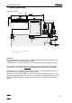
5.1 Setting up the Oven 5. Preparations Ensure that the set operating voltage matches the mains voltage before you switch the apparatus on. If this is not the case, the operating voltage must be changed over: 1. Disconnect mains plug. Detach all tubing and cable connections to the oven. Take out drying flasks. 2. Unscrew the 3 screws at the bottom of the oven at the front. 3. Unscrew the 3 screws at the green edge at the rear of the oven. 4. Carefully lift off top part of oven and lower to the front. 5.
5.1 Setting up the Oven 5.1 Setting up the Oven 6.1808.130 6.1805.180 6.1805.070 6.1805.180 6.1805.080 (6.1808.140) Unpack Oven and remove all protective coverings. 1. Insert 6.2407.020 Insert Tube in the heating chamber of the Oven and fasten it to the Oven with the clamp (red screw). The glass protrusion on the insert tube is positioned in the slot of the clamp. 2. Screw 6.2104.080 Cable onto temperature sensor of the insert tube and connect to the Pt1000 sockets of the Oven.
5.1 Setting up the Oven 7. Connect right drying flask to the gas connection of the Oven "From drying flask" using 6.1805.080 Tubing. 8. Set 6.2724.010 Dust filter onto the connection "Purge" of the Oven and set 6.1808.130 Adapter onto dust filter. Connect this adapter with the left outlet of the insert tube using 6.1805.180 tubing. 9. Set up the tubing connection "To Oven" to the right inlet of the insert tube with another 6.1805.180 Tubing. 10.
5.2 Connection of the 756 KF Coulometer or of a Titrino 5.2 Connection of the 756 KF Coulometer or of a Titrino The Titrino or the 756 Coulometer, resp., is connected to the 768 KF Oven as follows (warning: plug cable ends into proper sockets): A 768 707 A B C B 7XX D Kabel 6.2141.010 6.2141.010 cable If you wish to have the Oven data incorporated in the report of the 756 Coulometer, you have to connect the RS interfaces of the Coulometer and the Oven by means of 6.2125.110 cable.
5.2 Connection of the 756 KF Coulometer or of a Titrino 5.2.1 Installation of the coulometric cell (756 KF Coulometer) Generator electrode with drying tube Indicator electrode Equip the cell for gas inlet as follows: Introduce the tip in the SGJ 14/15 by means of 6.14446.060 stopper. Screw tip into stopper with nipple and O-ring from 6.2730.030. Tip 6.1543.060 Screw nipple from 6.2730.030 Stopper 6.1446.060 If you wish to aspirate the solvent automatically, set up gas inlet into the lateral aperture.
5.3 Connection of the 737 KF Coulometer 5.3 Connection of the 737 KF Coulometer The 737 KF Coulometer is connected to the 768 KF Oven as follows: 768 707 737 D A B C D 6.2141.000 cable Connection of the 684 KF Coulometer is analogous to that of the 737 KF Coulometer.
5.4 Connection of the outlet heating 5.4 Connection of the outlet heating If the 6.1830.000 Heatable Outlet Tubing is used, appreciably shorter determination times are achieved. The heatable outlet tubing should be used in all cases where problems arise with condensation water in the normal outlet tubing.
5.5 Connection of a printer 5.5 Connection of a printer A variety of printers can be connected to the RS232 interface of the Oven. If you connect a printer other than one of those mentioned below, ensure that the Epson mode is emulated or that it uses the international character set following the IBM Standard Table 437 and IBMcompatible graphics control characters. You may connect the KF Oven together with the Titrator at the same printer using the 2.145.0100 Auto-Switch.
5.6 Connection of a computer 5.6 Connection of a computer The computer can be connected as follows: 768 707 A B C D PC 6.2125.060 Kabel 6.2125.060 cable For connection to a 9-pin socket of the Pc you need 6.2125.110 cable.
6.1 Technical specifications 6. Appendix 6.1 Technical specifications Sample temperature 50...300 °C (Pt1000 resistance thermometer) Gas flow with built-in air pump 0... 15 L/h or ca. 250 mL/min (0 °C, 0 m a.
6.2 "Remote" socket 6.2 "Remote" socket 6.2.1 Pin assignment We accept no responsibility whatsoever for damage arising from improper interconnection for the instruments. Inputs Pin Meaning 21 Start 9 Stop 22 Terminate 12 Cond.
6.2 "Remote" socket 6.2.2 Status of the lines during the automatic determination Inputs Cond.ok Sequence a 12 Start a 21 Outputs Stop a Terminate 9 a 22 Ready a 5 Heat.Smpl a 17 Start a 18 Stop a 4 Terminate Error 1) a a 3 16 a=active Preparation Temp. not ok Ready (purge time) (cond.time) Sample heating Boat out Ready 1): The error signal is reset as soon as the fault has been rectified.
6.3 Checking sample temperature 6.3 Checking sample temperature For GLP requirements it may be necessary to check the sample temperature of the Oven with the 6.5615.000 measuring equipment. The actual measurement of the temperature is carried out with a type K thermal element (with yellow plug) and a suitable temperature measuring device. Purchase this measuring device separately at your laboratory equipment agency. Proceed as follows: 1.
6.4 Warranty and certificates 6.4 Warranty and certificates The warranty regarding our products is limited to rectification free of charge in our workshops of defects that can be proved to be due to material, design or manufacturing faults which appear within 12 months from the day of delivery. Transport costs are chargeable to the orderer. For day and night operation, the warranty is valid for 6 months. Glass breakage in the case of electrodes or other glass parts is not covered by the warranty.
6.4 Warranty and certificates Certificate of Conformity and System Validation This is to certify the conformity to the standard specifications for electrical appliances and accessories, as well as to the standard specifications for security and to system validation issued by the manufacturing company. Name of commodity: System software: Name of manufacturer: 768 KF Oven Stored in ROMs Metrohm Ltd.
6.4 Warranty and certificates Ionenanalytik • Analyse des ions • Ion analysis • Análisis iónico 768 KF Oven Metrohm Ltd. CH-9101 Herisau Switzerland Phone +41 71 353 85 85 Fax +41 71 353 89 01 EC Declaration of Conformity The METROHM AG company, Herisau, Switzerland hereby certifies, that the instrument: 768 KF Oven meets the requirements of EC Directives 89/336/EWG and 73/23/EWG.
6.5 Accessories, scope of delivery 6.5 Accessories, scope of delivery 768 KF Oven including the following accessories: 2.768.0010 1 Set septa (5 items) for 6.2701.060 Screw Cap ...................................................6.1448.040 1 Tip for gas inlet ...................................................................................................6.1543.060 2 Covers for drying flasks .......................................................................................6.1602.
6.5 Accessories, scope of delivery Accessories for outlet heating Heatable outlet tubing.............................................................................................6.1830.000 756 Coulometer: Stopper for heatable outlet tubing...........................................................................6.1446.170 737 Coulometer, cell without diaphragm: Stopper for heatable outlet tubing...........................................................................6.1446.
Index Index Texts which appear in the display are printed small and keys are marked by < >. Page numbers for operation via RS232 (green pages ) are shown in italics. A D Accessories ........................................60 add.heat.factor ....................................12 Attachment - computer ........................................55 - KF Coulometer .........................47, 49 - outlet heating .................................50 - printer.............................................
Index K Key - ......................................7 - ..................................7 - .........................................8 - .......................................9 - ........................................8 - ......................................7 - ......................................11 - ..........................................7 - ..........................................7 - ..........................
Index Sequence .............................................6