797 VA Computrace Hardware Manual 8.797.
Metrohm AG CH-9101 Herisau Switzerland Phone +41 71 353 85 85 Fax +41 71 353 89 01 info@metrohm.com www.metrohm.com 797 VA Computrace Hardware Manual 8.797.8001EN 08.
Teachware Metrohm AG CH-9101 Herisau teachware@metrohm.com This documentation is protected by copyright. All rights reserved. Although all the information given in this documentation has been checked with great care, errors cannot be entirely excluded. Should you notice any mistakes please send us your comments using the address given above. Documentation in additional languages can be found on http://products.metrohm.com under Literature/Technical documentation.
Inhaltsverzeichnis Table of contents 1 Introduction ..........................................................1 1.1 1.2 1.3 Instrument description.................................................................. 1 Parts and controls......................................................................... 2 Information about the Instructions for Use................................... 7 1.3.1 1.3.2 1.4 Organization............................................................................
Inhaltsverzeichnis 2.10.1 2.10.2 2.10.3 2.10.4 2.10.5 General composition.............................................................. 55 System description for a combined system for Brightener and Suppressor............................................................................. 56 System description for Suppressor determination .................. 59 System description for Brightener determination with MLAT . 61 System description for Brightener determination with LAT .... 65 2.11 Control lines....
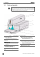
Inhaltsverzeichnis List of figures Fig. 1: Front of the 797 VA Computrace Stand ..................................... 2 Fig. 2: Rear of the 797 VA Computrace Stand ...................................... 3 Fig. 3: Right side view of the 797 VA Computrace Stand (fully equipped) .................................................................................. 4 Fig. 4: Left side view of the 797 VA Computrace Stand (fully equipped) .......................................................................
Inhaltsverzeichnis IV Fig. 26: Tubing connections for Suppressor determination (with DT) with the 838 Advanced Sample Processor ............................... 60 Fig. 27: Tubing connections for Suppressor determination (with RC) with the 838 Advanced Sample Processor ............................... 60 Fig. 28: Measuring head for Suppressor determination with the 838 Advanced Sample Processor.................................................... 61 Fig.
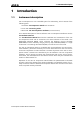
1.1 Instrument description 1 1.1 Introduction Instrument description 797 VA Computrace is a PC controlled system for voltammetry, which consists of the following parts: 1.797.0010 VA Computrace Stand with accessories 6.2151.020 Connecting Cable 6.6053.030 797 VA Computrace Software (current version) For a detailed description of the PC software «797 VA Computrace Software» see the 797 Software Manual.
1 Introduction 1.2 Parts and controls In this section you will find the numbers and designations of the parts and controls of the 797 VA Computrace Stand. The numbering applies throughout the instructions for use, i.e. bold numbers in the text (e.g. 7 ) refer to the parts and controls illustrated here. 2 3 4 5 6 1 7 8 Fig.
1.2 Parts and controls 9 10 11 12 Type: 1.797.0010 Nr.:___________ 13 14 MSB 1 15 16 MSB 2 MSB 3 USB 2 Remote PC Fuse 100 - 240 V: 1.6 A(TH) USB 1 Made by Metrohm Herisau Switzerland 19 18 Fig. 2: f = 50-60 Hz S= 120 VA WARNING - Fire Hazard - For continued protection replace only with the same type and rating of fuse 17 Rear of the 797 VA Computrace Stand 9 Connection for inert gas lead-off 15 Fuse cover Changing the fuses, see section 3.
1 Introduction 20 21 4 22 23 24 25 26 27 28 29 26 Fig. 3: 30 31 32 6 33 34 30 35 36 37 Right side view of the 797 VA Computrace Stand (fully equipped) 38 39 40 41 20 42 21 4 43 23 24 53 52 51 50 Fig. 4: 4 49 35 48 47 46 32 43 29 45 44 Left side view of the 797 VA Computrace Stand (fully equipped) 797 VA Computrace / Hardware-Manual 8.797.
1.2 Parts and controls 4 Stopper (6.2709.080) to close the pipetting opening 31 Electrode cable ”RE” connection for reference electrode 26 6 Gas wash bottle (6.2405.030) for inert gas supply (must be filled halfway with dist. H2O, see section 2.2.5) 32 Drive belt (6.1244.020) connection between drive wheel 35 and stirrer 28 20 Electrode cable ”WE” connection for working electrode (MME or RDE) 21 Multi-Mode Electrode (MME) (6.1246.020) details, see section 2.3 33 PTFE tube (6.1819.
1 Introduction 46 PTFE tube (6.1819.010) for optional supply of the waste solution to gas wash bottle 47 (attached) 47 Gas wash bottle (6.2405.030) for separating mercury from the waste solution (attached) 48 PTFE tube (6.1819.
1.3 Information about the Instructions for Use 1.3 Information about the Instructions for Use Please read through these Instructions for Use carefully before you put the 797 VA Computrace Stand into operation. The Instructions for Use contain information and warnings to which the user must pay attention in order to assure safe operation of the instrument. 1.3.1 Organization This 8.797.
1 Introduction 1.3.2 Notation and pictograms The following notations and pictograms (symbols) are used in these Instructions for Use: Mode 15 Parameter or entry value Part or control Hazard This symbol draws attention to a possible danger to life or of injury if the associated directions are not followed correctly. Warning This symbol draws attention to possible damage to instruments or instrument parts if the associated directions are not followed correctly.
1.4 Support documentation 1.4 Support documentation 1.4.1 Application-Bulletins The «Application Bulletins» is a collection of analytical methods, application examples and literature references. Of Metrohm's approximately 200 Application Bulletins, ca. 60 refer to Polarography and Voltammetry. All these Application Bulletins are available on request free of charge from your Metrohm supplier.
1 Introduction 1.4.2 No.
1.4 Support documentation ied from there. All these Application Notes are printed in the 8.757.2003 VA Applications Collection supplied with the instrument. All methods required to run the applications described in the Application Notes are installed when the 797 VA Computrace software is installed. 1.4.3 Monographs The «Metrohm Monographs» listed below impart theoretical fundamentals and general information on measurement techniques and sample preparation of polarography and voltammetry.
2 Installation 2 Installation This section offers a full description of the 797 VA Computrace Stand and provides detailed information on the various electrodes and the stirrer. Reliable operation of the instrument is assured only if you follow the instructions in this section exactly. 2.1 Setting up the instrument 2.1.1 Packaging The 797 VA Computrace Stand is supplied together with the separately packed accessories in special packages designed to ensure excellent protection.
2.2 Installation of the 797 VA Computrace Stand Any break in the grounding inside or outside the instrument can make it a hazard! Plug the mains cable into mains connection plug 16 of the 797 VA Computrace Stand (see Fig. 2). 2.2.2 Switching the instrument on/off The 797 VA Computrace Stand is switched on and off using mains switch 14. When the instrument is switched on, the pilot lamp 1 lights up. 2.2.3 Connection to the PC The 797 VA Computrace Stand is connected to the PC via USB Cable 6.2151.020.
2 Installation 797 PC 6.2151.020 USB Cable Fig. 5: Connection to PC In case your computer does not start if the 797 VA Computrace stand is switched on, it might is due to an older version of the BIOS. These BIOS versions are not able to handle USB Hubs in a correct way. In that case, start the computer first, and switch on 797 VA Computrace stand as soon as Windows booting is finished. 2.2.
2.2 Installation of the 797 VA Computrace Stand 3 Insertion of 4-way microtip (option) For automatic solution addition with Dosinos or Dosimats, the 6.1824.000 4way microtip has to be installed. Proceed as follows: • Remove stopper from nipple 27 and insert 4-way microtip 30 into nipple as far as it will go. • Tighten nipple using a 6.2739.010 Wrench until the 4-way microtip can no longer move.
2 Installation 55 Threaded opening for dummy stopper 45 (6.1446.040) 56 Threaded opening for dummy stopper 44 (6.1446.040) 57 Pipetting opening for the manual addition of solutions, closed with stopper 4 (6.2709.080) 58 Opening in operation with MME: for Multi-Mode Electrode 21 (6.1246.020) in operation with RDE: for 6.2709.040 Stopper 59 Threaded opening for FEP tubing 22 (6.1805.180, already permanently attached); inert gas supply to measuring vessel 7 60 Threaded opening for dummy stopper 25 (6.1446.
2.2 Installation of the 797 VA Computrace Stand 2.2.5 6 Install auxiliary electrode • Insert auxiliary electrode 43 (6.0343.000 Pt auxiliary electrode or GC auxiliary electrode, see section 2.6) in opening 54. • Attach electrode cable 41 (AE) to auxiliary electrode: push cable lug under the screw and then tighten screw firmly.
2 Installation 18 1 Fill gas wash bottle • Unscrew gas wash bottle 6 from measuring head arm 23. • Fill gas wash bottle half full with dist. H2O (for long-term measurements with supporting electrolytes such as Acetic acid / Acetate buffer or Ammonia / Ammonium chloride buffer, fill with supporting electrolyte; for measurements in organic solvents fill with the used solvent). • Screw gas wash bottle back on measuring head arm. 2 Connect inert gas supply • Attach one end of 6.1801.
2.2 Installation of the 797 VA Computrace Stand V2 37 V3 N2 V1 71 72 V4 6 53 Fig. 7: 6 37 Gas wash bottle (6.2405.030) for inert gas supply (must be filled only halfway with dist. H2O or supporting electrolyte, see also Fig. 3) Slotted screw for controlling the inert gas flow for de-aeration (see also Fig. 3) Note: 53 Scheme showing the inert gas connections at the 797 VA Computrace Stand The factory setting of ca.
2 Installation 2.3 Multi-Mode Electrode (MME) The Multi-Mode Electrode combines the most important polarographic and voltammetric mercury electrodes in a single construction: 2.3.1 • HMDE Hanging mercury drop electrode Mercury is forced through a glass capillary until a drop forms at the capillary tip and the entire voltage sweep performed on this single stationary drop; in general with preceding enrichment (stripping voltammetry).
2.3 Multi-Mode Electrode (MME) 73 74 75 76 72 77 71 78 88 71 Connection for inert gas supply 72 Connection for inert gas supply (for all MME operating modes) 73 Locking ring (4.420.2920) for slotted screw 74 79 80 74 Slotted screw (6.1247.040) with PTFE membrane and built-in spring 81 75 Sealing needle (6.1247.020) 82 76 Screw thread for slotted screw 74 83 77 Unused connection 84 78 Screw thread for slotted screw 79 85 79 Slotted screw (4.420.
2 Installation 2.3.2 Filling the MME with mercury When handling mercury, it is necessary to take special precautionary measures. These are described in detail in section 3.4. All actions involving the electrode and mercury vessels must be performed in or over the drip pan 91 supplied (see Fig. 9 - Fig. 11). The Hg reservoir 81 of the Multi-Mode Electrode 21 is filled with mercury of the highest degree of purity (mass fraction w ≥ 0.
2.3 Multi-Mode Electrode (MME) 2 Draw up mercury • Attach needle 90 to syringe 89. • Draw up 6 mL ultra pure mercury slowly and carefully using syringe. 3 Add mercury to MME • Lower syringe needle 90 into the top opening of the MME 21 between sealing ring 84 and sealing needle 75. • Expel mercury slowly and carefully from the syringe to allow it to flow into the Hg reservoir 81. The Hg reservoir 81 must never be filled more than 2/3 full with mercury. 2.3.
2 Installation 1 Install Multi-Mode Electrode in 797 VA Computrace Stand • With the measuring head arm 23 tilted back, slide the empty measuring vessel 7 into the holder 5 of the 797 VA Computrace Stand and then lower the measuring head arm. • Carefully insert Multi-Mode Electrode 21 in opening 58 of the measuring head 24 (during insertion, the tip of the capillary 87 must not touch the measuring head) and push in carefully as far as it will go. Avoid water drops touch the tip of the capillary.
2.3 Multi-Mode Electrode (MME) PUTRACE CONTROL window and clicking on freely out of the capillary. . The mercury drops • Select HMDE and click on . A single mercury drop is formed. Knock this off by gently tapping the MME 21 with your finger and check that the mercury flow has really stopped. Repeat this operation several times. • If mercury continues to flow, turn slotted screw 74 still further in a clockwise direction and repeat check.
2 Installation 96 93 Pump 94 Vacuum release tap 87 21 95 91 92 95 Fig. 10: Setting up the filling station Vacuum 93 Vacuum 94 1 2 87 3 91 92 Fig. 11: 21 Filling the capillary 21 Multi-Mode Electrode (6.1246.0020) 87 Glass capillary (6.1226.030) 92 Electrode holder (6.2615.030) 93 Filling tubing (6.1817.000) 91 Drip pan (6.2711.030) 26 797 VA Computrace / Hardware-Manual 8.797.
2.3 Multi-Mode Electrode (MME) 94 Filling cone (4.420.2860) (part of the filling tubing 93) 96 Tubing coupling (6.1809.000) (part of the filling tubing 93) 95 Gas wash bottle 5 Evacuating in vertical position • Place Multi-Mode Electrode 21 vertically in the electrode holder 92 (see Fig. 11-1). • Evacuate for ca. 2 min in this position. 6 Evacuating in inclined position • Carefully tilt Multi-Mode Electrode 21 in the electrode holder 92 to an inclined position and continue evacuating (see Fig. 11-2).
2 Installation 9 Connect Multi-Mode Electrode • Screw FEP tubing 34 for the inert gas supply into connection 71 of the Multi-Mode Electrode 21. • Screw FEP tubing 42 for the inert gas supply into connection 72 of the Multi-Mode Electrode. • Attach electrode cable 20 (WE) to screw connection 88 of the Multi-Mode Electrode push cable lug under the screw and then tighten screw firmly.
2.3 Multi-Mode Electrode (MME) 2.3.6 Storing the MME On completion of the measurements, the MME is stored in the 797 VA Computrace Stand so that the tip of the glass capillary 87 is immersed in pure water (or in the solvent used). This prevents blockage of the capillary by crystallized salts. An electrode treated in this manner can be taken out of the 797 VA Computrace Stand after a few hours and stored in air for a lengthy period without suffering any damage.
2 Installation can also lead to leakage of the MME, i.e. the mercury flow cannot be stopped any more. Proceed as follows: 30 1 Remove Multi-Mode Electrode from 797 VA Computrace Stand • Unscrew FEP tubing 34 and 42 from the MME, disconnect electrode cable 20 from MME. • Take Multi-Mode Electrode 21 out of measuring head 24 while gently tapping the MME to knock off any mercury drops on the glass capillary into the measuring vessel.
2.3 Multi-Mode Electrode (MME) 2.3.9 7 Mount new capillary Proceed as described in section 2.3.3. 8 Fill capillary Proceed as described in section 2.3.4 or section 2.3.5. Cleaning the MME If the mercury in the Multi-Mode Electrode is contaminated and this leads to disturbances, the MME must be cleaned and refilled with ultra pure mercury. Proceed as follows: 1 Remove Multi-Mode Electrode from 797 VA Computrace Stand • Unscrew FEP tubing 34 and 42 from the MME, disconnect electrode cable 20 from MME.
2 Installation 5 Clean MME • Clean inner compartments of the MME, contact pin 80 and the screw threads 76, 78 and 82 with a lint-free cloth. • If required, rinse all inner compartments of the MME and the unscrewed individual parts with dist. water and then dry with N2. Do not use any organic solvents. If you used water to clean the MME, make sure that the inside of the electrode has dried entirely. Residual moistness can cause problems during subsequent measurements.
2.3 Multi-Mode Electrode (MME) • Using a suitable coin, screw slotted screw 74 into the screw thread 80 until the contact surface of the black O-ring at the Plexiglas wall (thin, black stripe) is just visible below the metal thread. • Place Multi-Mode Electrode 21 with the opening 82 facing upwards in the electrode holder 92 (see Fig. 11-1). • Insert ring 83 in opening 86. • Push sealing ring 84 onto locking ring 85 and insert both in the opening 82.
2 Installation 2.4 Rotating disk electrode (RDE) The rotating disk electrode (RDE) can be used in place of the MME in the 797 VA Computrace Stand with different electrode tips as a working electrode. Version 2.797.0030 is delivered solely with a rotating plating electrode. For operation of the rotating disk electrode (RDE) the following accessories are required (see also section 4.3): • 6.1204.210 Driving axle for rotating disk electrode (RDE) with titanium axle • 6.1204.
2.4 Rotating disk electrode (RDE) 38 39 40 41 20 34 97 4 43 23 24 35 Fig. 12: 32 42 99 98 43 Measuring head arm with rotating disk electrode (RDE) 4 Stopper (6.2709.080) to close the pipetting opening 20 Electrode cable ”WE” connection for working electrode (RDE) 23 Measuring head arm carrier plate with permanently attached measuring head, raisable 24 Measuring head measuring vessel upper half made of PTFE; with openings for electrodes, stirrer, gas and liquid supply lines 32 Drive belt (6.
2 Installation 2.5 Reference electrode 2.5.1 Construction The complete reference electrode (RE) 26 comprises two parts: • 6.0728.0X0 Ag/AgCl-reference system (100) with ceramic diaphragm type D, diameter = 1 mm 6.0728.030 Reference system: LL-Ag/AgCl/c(KCl) =3 mol/L; 6.0728.020 Reference system: Ag/AgCl/c(KCl) = 3 mol/L; supplied in a holder filled with c(KCl) = 3 mol/L as standard 6.0728.010 Reference system: Ag/AgCl supplied dry (option) • 6.1245.
2.5 Reference electrode 2.5.2 Startup procedure The reference electrode 26 is supplied in modular form as the reference system 100 and the electrolyte vessel 101 and has first to be filled and assembled as follows: 1 Add internal electrolyte Filling of the reference system is necessary only when the optional 6.0728.010 Reference system supplied dry is used, if the internal electrolyte solution has to be renewed / filled up or if gas bubbles interrupt the electrical connection.
2 Installation 2.6 Auxiliary electrode 2.6.1 Construction The following electrodes can be used as the auxiliary electrode 43: • 6.0343.000 Pt auxiliary electrode supplied as standard • 6.1241.020 6.1247.000 Electrode holder and Glassy carbon tip together form the glassy carbon auxiliary electrode available as an option The construction of the two auxiliary electrodes and the designations of the individual parts are shown in Fig. 14. 2.6.2 Startup procedure The 6.0343.
2.7 Stirrer 43 43 Auxiliary electrode 111 111 114 115 116 113 2.7 112 Pt Auxiliary electrode (6.0343.000) 113 Pt tip (permanently attached) 112 Fig. 14: 111 Electrical connection for cable "AE" 114 Electrode holder (6.1241.020) 115 Locking ring 116 Glassy carbon tip (6.1247.000) Construction of the auxiliary electrode Stirrer The startup procedure for the stirrer is as follows: 1 Insert stirrer • Insert complete stirrer in opening 63 of the measuring head 24 as far as it will go (see Fig.
2 Installation 2.8 Connection of Dosing devices For the automatic addition of standard and auxiliary solutions, up to three Dosing devices (possible: 700/800 Dosino or 685/805 Dosimat) can be attached via the MSB sockets MSB1 - MSB3 (12) to the 797 VA Computrace Stand. For the connection of four additional Dosing devices, a 846 Dosing Interface can be used (from software version 1.2). The 846 Dosing Interface (ordering details see Section 4.3.
2.8 Connection of Dosing devices 700 Dosino and 800 Dosino 1 Mount Dosing unit on Dosino • Procedure, see Instructions for Use 700, section 2.2, and Instructions for Use 800, section 3.1 respectively. 2 Insert 4-way microtip in 797 VA Computrace Stand (see section 2.2.4) • Remove stopper from nipple 27 and insert 4-way microtip 30 into nipple as far as it will go (see Fig. 3 and Fig. 6). • Tighten nipple manually, so that the 4-way microtip can no longer move.
2 Installation • Note: The maximum allowed dose rate is 2 mL/min if the 4-way microtip is used to dose the solution in the measuring vessel. • Click . • Click on or MAIN WINDOW / Utility / Dosino control to open the DOSINO CONTROL window. • The connected Dosino and the mounted Dosing unit are automatically identified. • Click the the Dosino. button to empty and refill the Dosing unit installed on • Check if there are air bubbles left in the glass cylinder of the Dosing unit.
2.8 Connection of Dosing devices 2 Insert 4-way microtip in 797 VA Computrace Stand (see section 2.2.4) • Remove stopper from nipple 27 and insert 4-way microtip 30 into nipple as far as it will go (see Fig. 3 and Fig. 6). • Tighten nipple manually, so that the 4-way microtip can no longer move. • Pull the 4 lengths of PTFE tubing of the 4-way microtip 26 in succession from above through the opening 64. 3 Connect PTFE tubing to Exchange unit • Unscrew the attached 6.1805.
2 Installation used to dose the solution in the measuring vessel. • Click . • Click on or MAIN WINDOW / Utility / Dosino control to open the DOSINO window. • The connected Dosimat and the mounted Exchange Unit are automatically identified. CONTROL • Click the on the Dosimat. button to empty and refill the Exchange unit installed • Check if there are air bubbles left in the glass cylinder of the Exchange unit. If this is the case, repeat the flushing procedure by clicking the button.
2.8 Connection of Dosing devices Exchange unit 806 The Exchange unit 806 mounted on the Dosimat can be changed only in the exchange position which is reached after filling. Please proceed as follows: 1 Fill Exchange unit At the start of the VA Computrace program, the exchange unit is automatically filled. So this step is only necessary if the Dosimat has already been used during the running program session. • Click on CONTROL or MAIN WINDOW / Utility / Dosino control to open the DOSINO window.
2 Installation 2.9 Connection of 863 Compact Autosampler With the 863 Compact Autosampler connected to the 797 VA Computrace Stand, max. 18 samples can be transferred to the measuring vessel at the 797 VA Computrace Stand. It can only be used for the automated voltammetric trace analysis. After each measurement, the measuring vessel is rinsed by means of a 843 Pump Station.
2.9 Connection of 863 Compact Autosampler 2.9.1 Electrical connection Before any instruments are attached to the 797 VA Computrace Stand, the 797 VA Computrace Stand must be switched off using the mains switch 14. The 863 Compact Autosampler is connected to the socket “Remote 2” of the 843 Pump Station with the cable 6.1241.230 (Autosampler accessory). The socket “Remote 1” of the 843 Pump Station is connected to the socket “Remote” 15 of the 797 VA Computrace Stand with the cable 6.2141.
2 Installation 38 117 118 24 2 cm 2 cm 3 cm 119 120 48 Fig. 17: 47 46 Installation of accessories for rinsing and siphoning off 24 Measuring head 38 FEP tubing (6.1805.100) for waste solution lead-off (attached) 46 PTFE tube (6.1819.010) for supply of the waste solution to gas wash bottle 47 47 Gas wash bottle (6.2405.030) for separating mercury from the waste solution (attached) 117 FEP tubing (6.1805.180) for transferring the waste solution to gas wash bottle 47 118 FEP tubing (6.1805.
2.9 Connection of 863 Compact Autosampler 1 Install accessories at 797 VA Computrace Stand • Instead of the 6.1415.210 measuring vessel, install the 6.1456.210 measuring vessel at the 797 VA Computrace Stand. • Cut PTFE tube 119 (6.1819.010) to a length of max. 20 mm and insert from above in opening 56 of the measuring head 24. • Cut the bottom end of PTFE tube 120 (6.1819.010) diagonally and insert from above in opening 55 of the measuring head 24.
2 Installation 50 3 Connect 843 Pump Station • On both membrane pumps, replace the two 6.1446.040 threaded stoppers by two 6.1820.010 screw connectors. • Attach one end of a 6.1805.530 FEP tubing to the top screw connector of the siphoning pump (upper membrane pump). Attach the other end of the 6.1805.530 FEP tubing to one of the 6.1808.000 connection bushings of the waste container. • Attach one end of a 6.1805.530 FEP tubing to the lower screw connector of the siphoning pump (upper membrane pump).
2.9 Connection of 863 Compact Autosampler 2.9.
2 Installation 2 Set automation parameters • Select the Automation tab. • Select „813/863 Compact Autosampler“ for the field Sample processor in the Sample handling-part of the Automation tab. • Check the checkbox Relay box. • Normally, the default settings can be used for samples with 10 mL volume: 3 Test automation parameters • Fill two sample vessels with water and place them in position 1 and 2 on the sample rack of the 863 Compact Autosampler.
2.10 Connection of 838 Advanced Sample Processor • Start 797 VA Computrace Software (see Software Manual, section 2.2) 2 Load Autosampler method • Load Method 2 of the 863 Compact Autosampler (see Instructions for Use 863, section 3.4) 3 Load and modify VA method • Click on or 797 VA COMPUTRACE / Mode / Determination. or 797 VA COMPUTRACE / Window / Working method specification • Click on to open the WORKING METHOD SPECIFICATIONS window.
2 Installation Order no. 54 Instrument/Accessory Complete system Suppressor determination with DT / RC Brightener determination with MLAT Brightener determination with LAT 2.797.0030 797 VA Computrace for CVS 1 1 1 1 2.838.0310 838 Advanced VA Sample Processor 1 1 1 1 2.800.0010 800 Dosino 3 2 3 1 6.3032.120 807 Dosing Unit 2 mL 3 1 2 1 6.3032.250 807 Dosing Unit 50 mL 1 1 1 - 2.843.0040 843 Pump Station 1 1 1 1 6.1608.050 Bottle 100 mL 2 1 2 1 6.1608.
2.10 Connection of 838 Advanced Sample Processor 2.10.1 General composition Instruments for a complete system Fig. 19: Complete system for automation with the 838 Advanced Sample Processor Brightener/Suppressor analysis of electroplating baths can be fully automated with a 797 VA Computrace, an 838 Advanced Sample Processor, three 800 Dosinos, four 807 Dosing Units (one 50 mL, three 2 mL), and one 843 Pump Station.
2 Installation Pipetting needle adjustment Adjust 6.1835.040 or 6.1835.050 pipetting needle at the 838 Advanced Sample Processor to ensure that the lower end of the needle is positioned max. 0.5 mm above the bottom of the sample vessel. This is essential to guarantee a complete transfer of the sample from the sample vessel into the measuring vessel of the 797 VA Computrace Stand. Follow the Instructions for Use 838 for the definition of the "work position". 0.5 ... 1 mm 2.10.
2.10 Connection of 838 Advanced Sample Processor System description for Suppressor determination: 6.1805.530 to SIphoning Pump 5 x 6.1808.000 (already attached) 6.1805.530 6.1831.080 6.1805.530 6.1805.060 6.1805.530 6.1805.530 800 (1) 6.1828.020 800 (2) Metrohm Metrohm 800 Dosino 800 Dosino 50 mL 2 mL 2 mL VENT VENT VENT Waste 6.1808.210 6.2744.010 6.1543.060 800 (3) 6.2744.080 Metrohm 6.2833.020 6.1446.040 6.1805.100 6.1805.100 800 Dosino 6.1808.000 6.1543.060 6.1835.
2 Installation For the modification from a Suppressor system to a Brightener system, following procedure is recommended: 1 Permute Dosino 3 • Remove Dosino 3 from the 2 mL Dosing Unit attached to the 838 Advanced Sample Processor. • Attach Dosino 3 to the 2 mL Dosing Unit with Suppressor concentrate. 2 Unscrew 6.1831.080 PEEK capillary from needle clamp • Unscrew 6.2744.010 PEEK pressure screw from the 6.2744.080 M6 coupling at the robotic arm of the 838 Advanced Sample Processor. • Unscrew 6.2744.
2.10 Connection of 838 Advanced Sample Processor 2.10.3 System description for Suppressor determination Electrical connection Before any instruments are attached to the 797 VA Computrace Stand, the 797 VA Computrace Stand must be switched off using the mains switch 14. A composition with two Dosinos connected to the 797 is recommended for the Suppressor determination with the DT (dilution titration technique) or RC (response curve technique): Fig.
2 Installation Tubing connections for suppressor determination with DT 800 (1) Metrohm 6.1805.530 800 Dosino 6.1831.080 50 mL VENT 6.2744.010 6.1829.020 3 x 6.1808.000 800 (3) 6.2833.000 Metrohm 6.1805.530 3 x 6.1446.040 6.1835.040 6.1805.120 6.1808.000 6.1805.020 800 Dosino 2 mL 6.2057.040 6.1824.000 2 x 6.1446.040 VENT 6.1828.020 838 6.1805.530 to Siphoning Pump 6.1819.010 (2 cm) Fig. 26: Waste 6.1618.020 6.2744.010 6.2744.
2.10 Connection of 838 Advanced Sample Processor Tubing connections at the measuring head of the 797 843 Rinsing pump 6.1805.020 + 6.1819.010 (shorten to 2 cm) 800 Dosino for VMS (Port 1 Dosino 1) 6.1805.020 + 6.1819.010 (shorten to 2 cm) Fig. 28: Waste 6.1819.010 Waste 6.1805.180 843 Waste (Syphoning pump) 6.1805.470 (already attached) 800 Dosinos for suppressor standard / sample (Port 1 Dosino 3) 4-way microtip 6.1824.
2 Installation A composition with three to the 797 connected Dosinos is recommended for the Brightener determination with the Calibration technique MLAT: Fig. 29: Electrical connection for Brightener determination with the 838 Advanced Sample Processor and MLAT A 50 mL Dosing Unit filled with VMS is connected to Dosino 1. A 2 mL Dosing Unit filled with Brightener standard solution is connected to Dosino 2. A 2 mL Dosing Unit filled with Suppressor concentrate is connected to Dosino 3.
2.10 Connection of 838 Advanced Sample Processor Sample volume > 10 mL 6.1805.530 to siphoning pump 6.1446.040 5 x 6.1808.000 (already attached) 6.1805.530 6.1805.530 6.1805.530 800 (1) 800 (2) 800 (3) Metrohm Metrohm Metrohm 800 Dosino 800 Dosino 800 Dosino 50 mL 2 mL 2 mL VENT VENT VENT 6.1828.020 Waste 6.1805.060 6.1808.210 6.1543.060 6.2833.020 2 x 6.1446.040 6.1805.100 6.1805.100 6.1543.060 6.1835.050 6.1829.020 2 x 6.1808.000 2 x 6.1805.020 6.1805.120 6.1824.000 6.1805.
2 Installation Tubing connections at the measuring head of the 797 sample volume >10 mL 843 Rinsing pump 6.1805.020 + 6.1819.010 (shorten to 2 cm) Sample from 838 6.1805.120 + 6.1819.010 (shorten to 2 cm) Fig. 32: Waste 6.1819.010 Waste 6.1805.180 843 Waste (Syphoning pump) 6.1805.470 (already attached) 800 Dosinos for suppressor concentrate (Port 1 Dosino 3) + brightener standard (Port 1 Dosino 2) 4-way microtip 6.1824.000 800 Dosino for VMS (Port 1 Dosino 1) 6.1805.020 + 6.1819.
2.10 Connection of 838 Advanced Sample Processor For software settings and measurement procedures: see Software Manual 797 section 8.6, and Online-Help of the <797 VA Computrace Software> section Brightener Analysis with the 838 Advanced Sample Processor and MLAT. 2.10.5 System description for Brightener determination with LAT Electrical connection Before any instruments are attached to the 797 VA Computrace Stand, the 797 VA Computrace Stand must be switched off using the mains switch 14.
2 Installation Brightener sample volume > 10 mL 6.1805.530 to siphoning pump 3 x 6.1446.040 5 x 6.1808.000 (already attached) 6.1805.530 6.1828.020 800 (2) Waste Metrohm 6.1805.060 800 Dosino 6.1808.210 2 mL VENT 6.2833.020 3 x 6.1446.040 6.1805.100 6.1835.050 6.1543.060 3 x 6.1808.000 6.1805.020 6.1824.000 6.1805.120 6.1808.210 6.1808.000 6.1826.150 838 6.1819.010 (2 cm) Fig.
2.11 Control lines For software settings and measurement procedures: see Software Manual 797 section 8.6, and Online-Help of the <797 VA Computrace Software> section Brightener Analysis with the 838 Advanced Sample Processor and LAT. 2.
2 Installation 2.13 Communication diagrams for automation In this chapter, sequence diagrams are used to describe the communication between the devices for automation with a 838 Advanced Sample Processor. The communication sequence depends on the selected Calibration technique in the window WORKING METHOD SPECIFICATION. The 797 VA Computrace acts as master.
2.13 Communication diagrams for automation 2.13.1 Communication diagram VA Standard addition / Sample with calibration curve / Record calibration curve Dosinos 1..3 838 Advanced Sample Processor 797 VA Computrace 731 Relay Box Set line: Start 838 (TTL 3) Scan line : 838 ready (TTL 7) Ready (TTL 7) Set line: Siphoning (TTL 5) Wait siphoning time Prep Dosino 1,2,3 ? NO YES No.
2 Installation 2.13.2 Communication diagram LAT LAT Standard addition for brighteners / LAT Record intercept value Dosinos 1..3 838 Advanced Sample Processor 797 VA Computrace 731 Relay Box Set line: Start 838 (TTL 3) Scan line : 838 ready (TTL 7) Ready (TTL 7) Set line: Siphoning (TTL 5) Wait siphoning time Prep Dosino 1,2,3 ? NO YES No.
2.13 Communication diagrams for automation 2.13.3 Communication diagram MLAT MLAT Standard addition for brighteners Dosinos 1..3 838 Advanced Sample Processor 797 VA Computrace 731 Relay Box Set line: Start 838 (TTL 3) Scan line : 838 ready (TTL 7) Ready (TTL 7) Set line: Siphoning (TTL 5) Wait siphoning time Prep Dosino 1,2,3 ? NO YES No.
2 Installation 2.13.4 Communication diagram DT DT Suppressors with calibration curve / DT Record calibration curve Dosinos 1..3 838 Advanced Sample Processor 797 VA Computrace 731 Relay Box Set line: Start 838 (TTL 3) Scan line : 838 ready (TTL 7) Ready (TTL 7) Set line: Siphoning (TTL 5) Wait siphoning time Prep Dosino 1,2 ? NO YES No.
2.13 Communication diagrams for automation 2.13.5 Communication diagram "RC Record response curve" RC Record response curve Dosinos 1..3 838 Advanced Sample Processor 797 VA Computrace 731 Relay Box Set line: Start 838 (TTL 3) Scan line : 838 ready (TTL 7) Ready (TTL 7) Set line: Siphoning (TTL 5) Wait siphoning time Prep Dosino 1,2,3 ? NO YES No.
2 Installation 2.13.6 Communication diagram "RC Sample with response curve" RC Sample with response curve Dosinos 1..3 838 Advanced Sample Processor 797 VA Computrace 731 Relay Box Set line: Start 838 (TTL 3) Scan line: Waiting for START signal Ready (TTL 7) Set line: Siphoning (TTL 5) Wait siphoning time Prep Dosino 1,2,3 ? NO YES No.
3.1 Electrical safety 3 Safety 3.1 Electrical safety While electrical safety in the handling of the 797 VA Computrace Stand is assured in the context of the specifications IEC 61010-1 (protection class 1), the following points should be noted: • Mains connection Setting mains connection must be effected in accordance with the instructions in section 2.2.1.
3 Safety 3.2 Change fuses The fuses of the 797 VA Computrace are placed between the mains switch 14 and the mains connection plug 16 under the Fuse cover. To change them, proceed as follows: 1 Disconnect mains cable Disconnect mains cable from mains connection plug 16 of the 797 VA Computrace. 2 Remove fuse cover Using a screwdriver, lever out fuse cover 15 forwards until it opens.
3.4 Safety considerations concerning mercury 3.4 Safety considerations concerning mercury 3.4.1 Properties of mercury The most important properties of mercury (Hg) are listed in the Table below. This compilation allows the following summary: • Mercury is a heavy metal with a very high density and is liquid at room temperature. • Mercury is mobile at room temperature and tends to form drops because of its high surface tension.
3 Safety 3.4.2 Toxicity of mercury and its compounds Mercury and its compounds are toxic since they react with enzymes containing sulfur and decompose them with the formation of HgS. The toxicity depends on the chemical and physical state of the mercury [4, 8 – 10]: • Metallic liquid mercury is readily resorbed by the skin and finds its way through glandular passages into lower skin regions where it is oxidized and carried on as a salt.
3.4 Safety considerations concerning mercury with special laboratory aids: e.g. Mercurisorb-Roth™ from Roth, Karlsruhe/FRG; e.g. Mercury Sponge™ and Resisorb™ from Baker, Phillipsburg, N.J./USA • Empty reservoir of mercury trap regularly The storage container of the 6.2406.000 mercury trap should be emptied regularly and rinsed thoroughly several times. If the mercury trap is needed outside the fume cupboard, a minimum safety distance of 50 cm between the head and the mercury trap must be observed.
3 Safety 3.4.4 References dealing with mercury [1] [2] [3] [4] [5] [6] [7] [8] [9] [10] [11] [12] [13] [14] [15] 80 Documenta Geigy Wissenschaftliche Tabellen, 7. edition, page 210 (”Masseinheiten, Dichte”), Georg Thieme Verlag, Stuttgart (BRD), 1975 Berufsgenossenschaft der chemischen Industrie (Herausgeber) Quecksilber und seine Verbindungen Merkblatt, Seite 3...4, Verlag Chemie, Weinheim (BRD), 1980 Synowietz, C.; Schäfer, K. (Herausgeber) Chemiker-Kalender, 3.
3.4 Safety considerations concerning mercury [16] Quecksilberreinigung GIT 6 (1962), 351 797 VA Computrace / Hardware-Manual 8.797.
4 Appendix 4 Appendix 4.1 Technical data Subject to changes! The listed technical data apply to an ambient temperature of 25°C. Brief characterization PC-controlled system for voltammetry, set chemical workplace with potentiostat and measuring amplifier. With Multi-Mode Electrode or rotating disk electrode (RDE). Tilt-back measuring arm, integrated drip pan. Current measurement techniques DC NP DP SqW AC1 AC2 PSA CCPSA CV CVS CPVS Direct Current Normal Pulse Differential Pulse Square Wave (10 ...
4.1 Technical data Pulse amplitudes 1 mV … 1 V –1 … 1 V 0.15 mV … 1 V AC1, AC2: DP, NP: SQW: Current measurement Current ranges 10 nA … 10 mA in 7 ranges Current resolution 0.2 % of the current range Minimum current Imin 30 fA Maximum current Imax 80 mA Integration times 0.1 … 20 ms Multi-Mode Electrode MME (working electrode WE) Designation 6.1246.020 Electrode types DME (dropping mercury electrode) HMDE (hanging mercury drop electrode) SMDE (static mercury drop electrode) Drop surface 0.
4 Appendix Regeneration with 6.2802.000 Polishing kit or with 6.2802.020 Trimming tool (only for 6.1204.180) –1 Rotational speed 200, 400, 600, ... , 3000 min Speed constancy ±2% Reference electrode(RE) Reference system double-junction; 6.0728.0X0 Ag/AgCl Ref. system + 6.1245.010 Electrolyte vessel to be filled by user 6.0728.030 LL-Ag/AgCl(KCl) Reference system 6.0728.020 Ag/AgCl/c(KCl) = 3 mol/L 6.0728.010 Ag/AgCl/dry (Option); can be filled with any electrolyte.
4.1 Technical data Dummy Cell Use Connections Checking of the 797 VA Computrace Determination of the signal-to-noise ratio AE auxiliary electrode RE reference electrode WE-L working electrode linear mode (RC element) WE-D working electrode differential mode (peak/wave) Inert gas (in general nitrogen N2) Use Operation of MME de-aeration of sample solution (Not needed for electroplating bath analysis) Purity Required pressure min. 5.0 (99.999 %) p = 1 ± 0.
4 Appendix Cable 6.2141.170 (option, for the 863 Compact Autosampler) 6.2141.180 (option, for 838 Advanced Sample Processor) Sample changer Rinsing equipment 863 Compact Autosampler (2.863.0020, option) or 838 Advanced Sample Processor (2.838.0310, option) 843 Pump Station or 731 Relay Box (2.731.0010, option) with two 772 Pump units (2 x 2.772.0110, option) or two 823 Membrane Pump Units (2 x 2.823.0010, option), Adapter cable (6.2160.010) and Rinsing equipment (6.5323.010, Option).
4.1 Technical data Storage, transport –40…+70 °C Housing Material of cover Polyurethane rigid foam (PUR) with fire protection for fire class UL94VO, FCH-free Material of base Steel, enameled Material of measuring head arm Steel, enameled Dimensions Width 259 mm Height 240mm (544/620 mm with cover raised) Depth 530 mm Weight 9.7 kg (excl. accessories) 797 VA Computrace / Hardware-Manual 8.797.
4 Appendix 4.2 Scope of delivery Subject to changes! All dimensions are given in mm. 4.2.1 VA Computrace 2.797.0010 The 2.797.0010 VA Computrace System includes the following accessories: Quant. Order No. Description 1 1.797.0010 797 VA Computrace Stand Instrument without accessories 1 6.0343.000 Pt Auxiliary electrode 116 11 1 6.0728.020 11 Ag/AgCl reference system with ceramic diaphragm Ag/AgCl/c(KCl) = 3 mol/L Together with the 6.1245.
4.2 Scope of delivery Quant. Order No. 1 6.1226.030 Description Glass capillaries for 6.1246.020 Multi-Mode Electrode 116 Set of 10 incl. two 4.420.2800 sealing rings 1 6.1226.050 Glass capillaries (silanized) for 6.1246.020 Multi-mode electrode 116 Set of 10 incl. two 4.420.2800 sealing rings 1 6.1244.020 Drive belt made of EPDM (ethylene propylene rubber), set of 3 Connection motor – drive shaft (6.1246.010 or 6.1204.210) 1 6.1245.
4 Appendix Quant. Order No. 7 6.1446.040 Description Dummy stopper made of PVDF, with M6 thread ∅4.9 For closing the unused openings in the measuring vessel upper half 1 6.1801.080 21.5 PVC tubing for supply of the inert gas 7 4 Length L = 4 m 4 6.1808.000 Tubing coupling made of ETFE, with 2 M6 threads For the connection of 2 lengths of tubing with thread M6 (e.g. 6.1805.XXX) 1 6.1817.000 ∅10 M6 25 Filling tubing, made of PVC incl. 4.420.2860 Filling cone and 6.1809.
4.2 Scope of delivery Quant. Order No. 1 6.2406.000 Description Mercury drop catcher silver wire in plastic bottle For the destruction of mercury drops by amalgamation 1 6.2615.030 100 ∅32 Electrode holder 52 For filling and storing the 6.1246.020 Multi-Mode Electrode 80 1 6.2703.000 Stand ring made of PVC ∅63 To hold the 6.1415.210 measuring vessel outside the 797 VA Computrace Stand ∅53.2 50 1 6.2709.080 18 Stopper For closing the pipetting aperture of the 797 VA Computrace Stand 1 6.
4 Appendix Quant. Order No. 1 6.2816.020 Description Syringe made of PP, with Luer connection Volume V = 10 mL For filling the MME 102 1 6.2816.030 Needle for 6.2816.020 syringe ∅0.8 80 1 6.2151.020 USB Cable 797 – PC For connection of the 797 VA Computrace Stand to the PC via USB USB A – USB B (1.8 m) 92 1 6.6053.030 PC Software-CD «797 VA Computrace Software» 1 8.797.8001EN 1 8.797.8027 Registration card (German/English) for PC program «797 VA Computrace» 1 8.757.
4.2 Scope of delivery 4.2.2 VA Computrace 2.797.0020 The 2.797.0020 VA Computrace System includes the following accessories: Quant. Order No. Description 1 1.797.0010 797 VA Computrace Stand Instrument without accessories 7 6.1446.040 Dummy stopper made of PVDF, with M6 thread ∅4.9 For closing the unused openings in the measuring vessel upper half 21.5 1 6.1801.080 PVC tubing for supply of the inert gas 7 4 Length L = 4 m 4 6.1808.
4 Appendix Quant. Order No. 1 6.2709.080 Description 18 Stopper For closing the pipetting aperture of the 797 VA Computrace Stand 1 6.2711.040 76 Drip pan made of PS (polystyrene) 20 To be inserted in the 797 VA Computrace Stand 150 200 1 6.2739.000 Spanner for screwing down plastic nipples ∅10 ∅8 68 1 6.2151.020 USB Cable 797 – PC For connection of the 797 VA Computrace Stand to the PC via USB USB A – USB B (1.8 m) 94 1 6.6053.030 PC Software-CD «797 VA Computrace Software» 1 8.
4.2 Scope of delivery 4.2.3 VA Computrace 2.797.0030 The 2.797.0030 VA Computrace System includes the following accessories: Quant. Order No. Description 1 1.797.0010 797 VA Computrace Stand Instrument without accessories 1 6.0343.000 Pt Auxiliary electrode 116 11 1 6.0728.030 11 LL-Ag/AgCl rerference electrode for CVS Internal system with electrolyte KCl = 3 mol/L 116 1 6.1204.190 Platinum electrode tip M3 Metal electrode tip made of platinum (Pt), electrode disk diameter 1 mm ±0.
4 Appendix Quant. Order No. 1 6.1204.210 Description Driving axle for rotating disk electrode (RDE) for VA Stands 46 14 1 6.1244.020 Drive belt made of EPDM (ethylene propylene rubber), set of 3 Connection motor – drive shaft (6.1246.010 or 6.1204.210) 1 6.1245.010 15 Electrolyte vessel with ceramic diaphragm B-NS 14/15 Together with the 6.0728.020 Ag/AgCl reference system forms a complete reference electrode (double-junction construction, assembly, see section 2.5.2) 82 ∅5 1 6.1415.
4.2 Scope of delivery Quant. Order No. 4 6.1808.000 Description Tubing coupling made of ETFE, with 2 M6 threads ∅10 M6 For the connection of 2 lengths of tubing with thread M6 (e.g. 6.1805.XXX) 1 6.1824.000 25 4-way microtip made of PTFE 700 With 4 lengths of PTFE tubing with connection nipples with thread M6 for the attachment of 4 Dosing devices. 100 1 1 6.2122.0X0 6.2308.
4 Appendix Quant. Order No. 1 6.2709.080 Description 18 Stopper For closing the pipetting aperture of the 797 VA Computrace Stand 1 6.2711.040 76 Drip pan made of PS (polystyrene) 20 To be inserted in the 797 VA Computrace Stand 150 200 1 6.2739.000 Spanner for screwing down plastic nipples ∅8 ∅10 68 1 6.2802.000 Polishing kit for mechanical regeneration of the active surface of 6.1204.XXX electrode tips comprising: 1× 2 g α-Al2O3 (0.3 μm) 1× polishing cloth 1 6.2151.
4.3 Options 4.3 Options 4.3.1 General options Order No. 6.0728.010 Description 11 Reference system 6.0728.010 Ag/AgCl Reference Electrode Internal system without electrolyte 11 6.0728.020 Ag/AgCl Reference Electrode Internal system with electrolyte KCl = 3 mol/L 6.0728.030 LL Ag/AgCl reference electrode for CVS Internal system with electrolyte KCl = 3 mol/L 116 6.0728.040 LL Ag/AgCl (gel) reference electrode for CVS Internal system with electrolyte KCl = 3 mol/L (gel) 6.1204.
4 Appendix Order No. Description 6.1204.220 Driving axle for rotating disk electrode (RDE) with titanium axle and mercury contact for VA Stands 6.1241.020 Electrode holder to take the 6.1247.000 glassy carbon rod Together with the 6.1247.000 glassy carbon rod forms the GC auxiliary electrode. 65 ∅2.1 6.1247.000 Glassy carbon tip 65 ∅2 Together with the 6.1241.020 electrode holder forms the GC auxiliary electrode. 6.1247.040 Slotted screw 20 Slotted screw with PTFE membrane. 6.1415.
4.3 Options Order No. 6.1450.210 Description ∅78 Measuring vessel Made of PFA (polyfluoralkyloxycopolymer), incl. 6.2036.000 holding ring 80 Volume: 10 ... 90 mL ∅23 6.2709.040 Stopper made of PVC, incl. 2 E.301.0004 O-rings of NBR (nitril rubber) For closing the MME opening when the RDE is used; with two dummy holes (thread M6) for holding the two MME gas lines not used in operation with the RDE. 6.2802.000 Polishing kit for mechanical regeneration of the active surface of 6.1204.
4 Appendix Order No. 6.3032.XXX 6.5323.010 Description Dosing unit 807 Burette unit for Metrohm 700 and 800 Dosino, with glass cylinder, four dosing ports (In- and Outlets) and integrated data chip; transparent housing. 6.3032.120 burette volume V = 2 mL 6.3032.150 burette volume V = 5 mL 6.3032.210 burette volume V = 10 mL 6.3032.220 burette volume V = 20 mL 6.3032.250 burette volume V = 50 mL Rinsing equipment for 797 VA Computrace incl.
4.3 Options Quant. Order No. 1 6.1204.140 Description Au - Electrode tip M3 Forms the rotating disc electrode (RDE). together with the 6.1204.210 Drive shaft. Shaft material: PEEK Disk diameter: 2.0 ± 0.1 mm 52.5 Concentricity error: ≤ 0.2 mm ∅7 1 6.1204.210 Driving axle for rotating disk electrode (RDE) for VA Stands 46 14 1 6.1241.020 Electrode holder to take the 6.1247.000 glassy carbon rod Together with the 6.1247.000 glassy carbon rod forms the GC auxiliary electrode. 65 ∅2.1 1 6.
4 Appendix Quant. Order No. 1 6.1415.150 Description Measuring vessel borosilicate glass, incl. 6.2036.000 holding ring ∅78 Volume: 5 ... 70 mL 80 ∅23 1 6.2709.040 Stopper made of PVC, incl. 2 E.301.0004 O-rings of NBR (nitril rubber) For closing the MME opening when the RDE is used; with two dummy holes (thread M6) for holding the two MME gas lines not used in operation with the RDE. 1 6.2802.000 Polishing kit for mechanical regeneration of the active surface of 6.1204.
4.3 Options Quant. Order No. 1 6.1204.210 Description Driving axle for rotating disk electrode (RDE) for VA Stands 46 14 1 6.1241.020 Electrode holder to take the 6.1247.000 glassy carbon rod Together with the 6.1247.000 glassy carbon rod forms the GC auxiliary electrode. 65 ∅2.1 1 6.1245.010 15 Electrolyte vessel with ceramic diaphragm Together with the 6.0728.020 Ag/AgCl reference system forms a complete reference electrode (double-junction construction, assembly, see section 2.5.
4 Appendix Quant. Order No. 1 6.2802.000 Description Polishing kit for mechanical regeneration of the active surface of 6.1204.XXX electrode tips comprising: μm) 4.3.4 1 × 2 g α-Al2O3 (0.3 1 × polishing cloth 6.5327.020 MVA-CVS: Equipment for CVS/CPVS Quant. Order No. 1 6.0343.000 Description Pt Auxiliary electrode 116 11 1 6.0728.030 11 LL-Ag/AgCl Reference electrode for CVS Internal system with electrolyte KCl = 3 mol/L 116 1 6.1204.
4.3 Options Quant. Order No. 1 6.1204.210 Description Driving axle for rotating disk electrode (RDE) for VA Stands 46 14 1 6.1245.010 15 Electrolyte vessel with ceramic diaphragm Together with the 6.0728.020 Ag/AgCl reference system forms a complete reference electrode (double-junction construction, assembly, see section 2.5.2) B-NS 14/15 82 ∅5 1 6.1415.210 Measuring vessel borosilicate glass ∅78 Volume: 10 ... 90 mL 80 ∅23 1 6.1415.
4 Appendix Quant. Order No. 1 6.2802.000 Description Polishing kit for mechanical regeneration of the active surface of 6.1204.XXX electrode tips comprising: 1× 2 g α-Al2O3 (0.3 μm) 1× polishing cloth 4.3.5 Accessories for the automated addition of auxiliary solutions It is recommended to use a 800 Dosino for the automated addition of auxiliary solutions (standards, electrolytes, etc.): Quant. Order No. 1..3 2.800.0010 Description 800 Dosino Dosing device to 797 VA Computrace Stand.
4.3 Options higher mL range: Quant. Order No. 1 6.3032.250 50mL Dosing unit 807 50mL Burette unit for Metrohm 700 and 800 Dosino, with glass cylinder, four dosing ports (In- and Outlets) and integrated data chip; transparent housing. 1 6.1608.070 Glass bottle 2 L 1..2 6.1618.020 Thread adapter S40 1 6.1805.020 FEP tubing L = 52 cm 1 6.1805.120 FEP tubing L = 100 cm 1 6.1819.010 PTFE tube L = 86 mm 4.3.
4 Appendix Quant. Order No. 1 6.5323.010 Description Rinsing equipment for 797 VA Computrace incl. the following accessories: 1 1 × × 6.1446.040 6.1456.210 2 2 2 1 1 1 4 1 2 1 4 1 1 × × × × × × × × × × × × × 6.1602.105 6.1618.050 6.1621.000 6.1805.020 6.1805.100 6.1805.180 6.1805.530 6.1808.000 6.1819.010 6.1819.020 6.1820.020 6.1828.020 6.1829.
4.3 Options Quant. Order No. Description 1 6.2141.290 Connection cable 843 Pump Station - 838 Advanced Sample Processor (standard) 1 6.2141.180 Cable 797-838-731 (alternative) Connection cable for 731 Relay Box and 838 Advanced Sample Processor to the 797 VA Computrace 2 6.2160.010 Adapter cable (alternative) Connection cable for 823 Membrane Pump Units to the 731 Relay Box 1 6.5323.010 Rinsing equipment for 797 VA Computrace incl. the following accessories: 1 1 × × 6.1446.040 6.1456.
4 Appendix 4.4 Validation / GLP GLP (Good Laboratory Practice) requires, among other things, that the precision and correctness of analytical instruments is checked at regular intervals by using SOPs (Standard Operating Procedures, SOP). In the 797 VA Computrace Software, a GLP Wizard is integrated. If this function is activated, the GLP Wizard monitors your system, reminds you of due verifications, leads you through verifications and creates your GLP-report.
4.5 Warranty and certificates 4.5 Warranty and certificates 4.5.1 Warranty The warranty on our products is limited to defects that are traceable to material, construction or manufacturing error, which occur within 12 months from the day of delivery. In this case, the defects will be rectified in our workshops free of charge. Transport costs are to be paid by the customer. For day and night operation, the warranty is limited to 6 months.
4 Appendix 4.5.2 Declaration of Conformity This is to certify the conformity to the standard specifications for electrical appliances and accessories, as well as to the standard specifications for security and to system validation issued by the manufacturing company. CH-9101 Tel. Fax Herisau, Switzerland +41 71 353 85 85 +41 71 353 89 01 www.metrohm.com Name of commodity 797 VA Computrace Name of manufacturer Metrohm Ltd.
4.6 Index 4.5.3 Quality Management Principles Metrohm Ltd., CH-9101 Herisau, Switzerland CH-9101 Herisau/Switzerland E-Mail info@metrohm.com Internet www.metrohm.com Metrohm Ltd. holds the ISO 9001 Certificate, registration number 10872-02, issued by SQS (Swiss Association for Quality and Management Systems). Internal and external audits are carried out periodically to assure that the standards defined by Metrohm’s QM Manual are maintained.
4 Appendix 823 Membrane Pump Units Ordering designation..............111 838 Advanced Sample Processor Brightener determination MLAT66 Brightener determination with MLAT .......................................63 Complete system ......................56 Delivery option .......................111 Pipetting needle adjustment .....57 Suppressor determination.........60 Tubing connections for the rinsing equipment................................56 846 Dosing Interface ....................40 Ordering designation.
4.6 Index Electrical connection 111 Figure.......................................39 Electrical safety ............................76 Electrode cable 41 (AE) Connection to auxiliary electrode17 Electrode cable 20 (WE) Connection to RDE ...................15 Figure.........................................5 Electrode cable 31 (RE) Attachment to reference electrode ................................................37 Connection to reference electrode ................................................16 Figure......
4 Appendix For Brightener determination with the 838 and MLAT ...................65 For Suppressor determination with the 838 ....................................62 Measuring head 24 Equipping .................................14 Figure.............................5, 15, 49 Measuring head arm 23 Figure.................................15, 35 Measuring head arm23 Figure.........................................5 Measuring head for Suppressor determination with the 838..........62 Measuring head24 Figure........
4.6 Index Safety directions...........................87 Safety specifications .....................87 Scheme of inert gas connections ..19 Screw connection 88 Connection of electrode cable 20 ................................................17 Figure.......................................21 Screw thread 76 Figure.......................................21 Screw thread 78 Figure.......................................21 Screw thread 82 Figure.......................................21 Sealing needle 75 (6.1247.