
Owner manual

3.3 Defining work positions
■■■■■■■■■■■■■■■■■■■■■■
14
■■■■■■■■
1
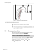
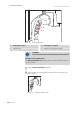
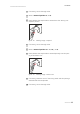
Figure 14 Alignment with the retaining plate
1
Sample tube swing range
3
Retighten the screw (11-2) on the clamping fastener.
4
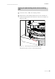
Check whether the distance to the sample rack is consistent with Fig-
ure 12 and whether the position in relation to the retaining plate (see
Figure 14, page 14) is suitable.
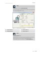
3.3 Defining work positions
The Liquid Handling Station has three positions. These work positions
have to be defined in the software (e.g. MagIC Net™).
Defining the work positions for the sample tube
The work positions are defined in the software as external positions.
You can find the value settings under the following path:
Configuration ▶ Devices ▶ Properties ▶ Tower ▶ Swing
Head ▶ External position