IS1000 Series Radio Frequency Bar Code Reader Configuration Guide Metrologic Instruments GmbH Dornierstrasse 2 82178 Puchheim GERMANY Tel.
Metrologic Instruments GmbH makes no guaranteed declaration or offer concerning the contents or use of this manual, and notably refutes any express or implicit liability as regards the merchandisable quality or suitability for a particular use of the product. In addition, Metrologic Instruments GmbH reserves the right to update this publication and to make changes at any time without notice.
Metrologic Instruments GmbH Donierstrasse 2 82178 Puchheim GERMANY Tel.: +49 (0)89 890 190 Fax: +49 (0)89 890 19 200 info@europe.metrologic.com Metrologic Instruments Italia S.r.L. Via Emilia 70 40064 Ozzano Dell'Emilia (BO) ITALY Tel.: +39 051 651 19 78 Fax: +39 051 652 13 37 Metrologic Eria Ibérica S.A. Julian Camarillo 29, D1 Bajo 28037 Madrid SPAIN Tel.: +34 91 327 24 00 Fax: +34 91 327 38 29 Metrologic Eria Ibérica S.A. Consell de Cent 106 – 108 – 3° 3a 08015 Barcelona SPAIN Tel.
TABLE OF CONTENTS 1. INTRODUCTION............................................................................................................. 1 1.1. Default Configuration (factory setting) .............................................................. 3 2. COMMUNICATION MODES........................................................................................... 5 2.1. RS232.................................................................................................................... 6 2.1.1.
3.4.1. 3.4.2. 3.4.3. 3.4.4. 3.4.5. 3.4.6. 3.4.7. 3.4.8. Types of UPC/EAN Authorized................................................................ 31 Transformations....................................................................................... 31 Add-On Options ....................................................................................... 32 Leading Prefixes for P.O.S. Systems ...................................................... 33 Flag Option ..........................................
4.5. Setting the Timers ............................................................................................. 51 4.5.1. Timer T1 .................................................................................................. 51 4.5.2. Timer T2 .................................................................................................. 52 4.5.3. Timer T3 .................................................................................................. 52 5. EDITING MODE.....................
Page intentionally left blank IS1000 – Configuration Guide vi
1. INTRODUCTION This manual contains information about configuration IS1000 laser reader and decoder present in the radio base. The installation procedures and technical description are described in the IS1000 Installation and User’s Guide. The IS1000 Connection List contains the connection numbers (or ID) and the cable references to be used for Keyboard-Wedge communication on PCs and terminals, for communication with P.O.S. systems and Notebooks.
Once the radio base is powered on, each parameter value can be changed simply by scanning, with the laser reader, the codes appearing in this manual with respect to configuration sequence.
1.1.
Page intentionally left blank IS1000 – Configuration Guide 4
2. COMMUNICATION MODES The radio base is equipped with a decoder offering a multi-interface communication port. The default communication mode is RS232 (9600 baud, 7 data bits, parity even, 1 stop bit, end message: CR LF).
2.1. RS232 Use the codes on this page through to page 11 to activate and adjust the RS232 parameters. RS232 MODE ACTIVATED * 2.1.1.
2.1.2. Data Bits 7* 8 EVEN * MARK ODD SPACE 2.1.3. Parity 2.1.4.
2.1.5. End of Message Character One character can be systematically transmitted with each code to indicate the end of message: CR/LF * STX…ETX HT SUITE (MINITEL) NONE LF CR EOT Other characters or complete fields can be added to the message using the Preamble / Postamble function (see appendix 6.3, page 58) or the Editing Mode (see chapter 5, page 53).
2.1.6.
2.1.7. ACK/NAK Protocol Once this protocol is activated, the decoder waits for an acknowledgment from the host system: • ACK (06 hexa) means: message correctly received by the host system. • NAK (15 hexa) means: message incorrectly received by the host, upon reception of this character the decoder resends the message. ACK/NAK ACTIVATED ACK/NAK DISACTIVATED * 2.1.8.
2.1.10. PC-Term Mode Some applications use several RS232 terminals connected to a PC host system configured in PC-Term mode. When a character is typed on a keyboard of a terminal, its scan code value is transmitted to the PC instead of its ASCII value. Then, upon reception, the PC sends back the corresponding ASCII character to display on the screen. Therefore, once this mode is activated, the decoder sends the scan code value of each character read.
2.2. Keyboard-Wedge In this mode the radio base is connected between the keyboard and the computer (or terminal). Data is emulated by the decoder as if it was typed on the keyboard.
PC Keyboard-Wedge ID: PC Keyboard Type ! ID ALT Mode 114 Belgian 644 French 1 German 104 Hungarian 437 Italian 123 Spanish 313 Swedish 169 Swiss 148 UK 611 US 11 Note: For other Keyboard-Wedge interfaces, please refer to the IS1000 Connection List to obtain ID and cable reference.
2.2.1. End of Message Character One of the characters below can be systematically emulated by the decoder as the end of message character: RETURN * FIELD EXIT ENTER TAB + CR/LF ; FEED ; SEND LF FIELD ADVANCE NO CHARACTER Other characters, signs, function keys or fields can be added using the Preamble / Postamble function (see appendix 6.3, page 58) or the Editing Mode (see chapter 5, page 53). 2.2.2.
2.2.3. Types of Numeric Characters This function allows the emulation of the numeric characters of the numeric pad or those located on top of the keyboard. Use this function if trouble occurs with upper/lower case keyboard modes. NUMERIC PAD NUMERICS LOCATED OVER THE ALPHANUMERIC PAD * ! Note: If the option Numeric Pad is chosen, the numeric pad of the keyboard must be also turned on (or locked) for correct operation. 2.2.4.
2.2.5. "WYSE" Time-Out Some Keyboard-Wedge connections on some Wyse terminals can drop characters especially when a string of identical characters appears in a code.
2.3. P.O.S. (Point Of Sale) Systems The main communication modes with P.O.S. systems are: • RS232 • Keyboard-Wedge • OCIA • RS485 To set RS232 communication use pages 6 to 11 to adjust the transmission parameters. To set a Keyboard-Wedge, OCIA or RS485 communication use page 12 of this manual; scan the code Keyboard-Wedge Mode Activated and enter your ID. ! Note: Please refer to the IS1000 Connection List to obtain ID and cable reference.
2.4. Wand Emulation Scan this code to activate the wand emulation mode: WAND EMULATION MODE ACTIVATED Then select the symbology to be emulated using the Bar Code Pad page 12, without reading the code Keyboard-Wedge Mode Activated: Emulation ID Code 39 69 Interleaved 2/5 68 UPC/EAN * 70 * Only 8 or 13 characters messages are accepted for this emulation Then adjust the following transmission parameters. 2.4.1.
2.4.2. Bar/Space Polarity BAR = 0, SPACE = 1 BAR = 1, SPACE = 0 * 2.4.3.
2.5. Laser Emulation With this mode, data are transmitted as code 39 data coming from a TTL hand held laser or CCD scanner. Scan this code to activate this mode: LASER EMULATION MODE ACTIVATED ! Note: For the radio base connector pin-out, refer to the IS1000 Installation and User’s Guide.
3. SYMBOLOGIES Many bar code symbologies have been developed to suit many data capture applications in different domains (retail, industry, medical, transport…) requiring simple or complete sets of characters (numeric, alphanumeric, full ASCII set…) with various density performances. Each symbology has options which must be carefully checked and adjusted by the user. Some samples are printed in appendix 6.12, page 82.
3.1. Symbology Selection NEW SELECTION This code must be read to initialize any new selection of symbologies CODE 39 * INTERLEAVED 2/5 * UPC/EAN * MONARCH/CODABAR * CODE 128 * EAN 128 * These six bar code symbologies are the most commonly used and are active by default. Other symbologies can be selected on the next page. ! Note: • If no symbology is selected after the reading of New Selection code, the above six symbologies will remain activated.
STANDARD 2/5 MSI PLESSEY TELEPEN CODE 93 MATRIX 2/5 IATA BC 412 ** 3W7 Reserved # 1 Reserved # 2 Reserved # 3 Once your selection is completed, consult the next pages to verify and adjust the options you require for each symbology. ** Strictly reserved for IBM and authorized companies; require a specific firmware.
3.2. Code 39 This is the most popular alpha-numeric bar code symbology. It has a set of 43 characters (alphanumeric and a few symbols) and can be used with or without a check digit. 3.2.1. Standard/Full ASCII The Code 39 Full ASCII option allows the transmission of the 128 ASCII characters. Each ASCII character is a combination of two Code 39 characters. It can be very useful specially to transmit control characters (STX, ETX, TAB, EOT…) as preambles or postambles in a message (see appendix 6.3, page 58).
3.2.3. Multiread ACTIVATED DISACTIVATED * The Multiread function permits the temporary storage of one or more codes in the decoder's memory which will then be transmitted in a single string message. To operate the Multiread function, the desired group of codes to be first stored must have a Multiread Character as the leading character. This character can be chosen in the Multiread Character Table (see appendix 6.9, page 67; default is SPACE character) after reading code Activated.
3.2.5. Pharmacode or Pharma 32/39 This symbology is used only in Italy. The encoding uses the Code 39 standard but the decoding performs a transformation of the digits using a translation table. Example: The Code 39 message: 2 D W W K P will be transformed into 080638517. To activate this symbology, the code New Selection must be read first. NEW SELECTION * PHARMACODE ACTIVATED START/STOP NOT TRANSMITTED * START/STOP TRANSMITTED CHECK DIGIT TRANSMITTED * CHECK DIGIT NOT TRANSMITTED 3.2.6.
3.2.7. Start/Stop This function activates the transmission of the start and stop characters (sign ¸). TRANSMITTED NOT TRANSMITTED * 3.2.8. Modulo 43 Algorithm Code 39 is strongly self checked and most situations do not require a check character. If a specific application requires exceptional data security, a check character can be added as the last character of the code. Example: Message: 12345/ABCDE Sum of values: 1 + 2 + 3 + 4 + 5 + 40 + 10 + 11 + 12 + 13 + 14 = 115 Divide 115 by 43.
3.3. Interleaved 2/5 This symbology is only numeric and offers a very high density of characters per inch due to its interleaved encoding system. The decoding is very easy even if the symbols are poorly printed. These advantages make it very popular for industrial applications. But to avoid missing characters when scanning is incomplete, it has to be used with fixed lengths (see pages 28 or 29) or variable lengths with a check digit (see page 30). 3.3.1.
3.3.2. Fixed Length(s) Authorized and Set Using the Numeric Pad Select the number of code length(s) desired (1 to 4): ONE TWO THREE FOUR Select the N° of the length to be adjusted: LENGTH N° 1 LENGTH N° 2 LENGTH N° 3 LENGTH N° 4 Enter the desired number of characters using the Numeric Pad page 81 VALIDATION Go back to adjust a next N° of length or read the code End of Configuration if no other lengths is desired. ! Note: In this mode, the code lengths are saved after power-off.
3.3.3. Variable Lengths Authorized ACTIVATED CHECK DIGIT VERIFIED BUT NOT TRANSMITTED CHECK DIGIT VERIFIED AND TRANSMITTED How to calculate the check digit value: Example: Message: 14356 Add the odd positions: 1 + 3 + 6 = 10 Multiply by 3 = 30 Add the even positions.
3.4. UPC/EAN This symbology is mainly used for retail applications. It has fixed lengths (8 or 12 characters for UPC, 8 or 13 characters for EAN) and uses a check digit as the last character and is only numeric. Two or five supplemental digits called Add-On can be added to the right hand size of the codes. 3.4.1. Types of UPC/EAN Authorized ALL UPC/EAN CODES * EAN 13 AUTHORIZED UPC A AUTHORIZED EAN 8 AUTHORIZED UPC E AUTHORIZED ! Note: Several selections can be accumulated. 3.4.2.
3.4.3.
3.4.4. Leading Prefixes for P.O.S. Systems Leading characters can be transmitted with each code to inform the P.O.S. system with the type of UPC or EAN read. The prefixes are: FF for EAN 8, F for EAN 13, A for UPC A, E for UPC E. PREFIXES TRANSMITTED PREFIXES NOT TRANSMITTED * 3.4.5. Flag Option The Flag is the first digit of the code. It can be transmitted or suppressed.
3.4.6. Check Digit Options EAN 13 CHECK DIGIT TRANSMITTED * EAN 13 CHECK DIGIT NOT TRANSMITTED EAN 8 CHECK DIGIT TRANSMITTED * EAN 8 CHECK DIGIT NOT TRANSMITTED UPC A CHECK DIGIT TRANSMITTED * UPC A CHECK DIGIT NOT TRANSMITTED UPC E CHECK DIGIT TRANSMITTED * UPC E CHECK DIGIT NOT TRANSMITTED 3.4.7. Product Code The product code is represented by the last six digits (without the check digit) can be transmitted alone: PRODUCT CODE ONLY ALL CHARACTERS TRANSMITTED * 3.4.8.
3.5. Monarch/Codabar The Codabar (or Monarch) is a very high reliable bar code which has been designed specially for medical applications such as blood bag identification. Its character set contains numerics and four symbols. 3.5.1. Start/Stop NOT TRANSMITTED * TRANSMITTED a b c d Small * ABCD BLOCK a, b, c, d are the different start/stop characters. 3.5.2. Concatenation STANDARD CONCATENATED * This function permits the capture of two codes with only one scan.
3.6. Code 128 This symbology offers a great flexibility with its three sets of characters: • Set A: upper case alphanumeric characters and all ASCII control characters. • Set B: upper and lower case alphanumeric characters and some symbols. • Set C: numeric only but which a very high density of characters per inch. Good quality printed codes are recommended due to the continuous structure (no gaps between characters) and the four types of bar and space widths.
3.7. UCC/EAN 128 This symbology is fully compatible with Code 128. The main difference between EAN 128 and conventional Code 128 is that EAN 128 codes always contain a reserved non-data character, function 1 (FNC1), as the first character after the start character. This FNC1 character acts also as a separator of fields in the code.
3.8. Standard 2/5 This symbology is numeric only and uses the same encoding system as the code Interleaved 2/5 but only the bars are significant. The problem of reliability is also the same in case of incomplete scanning of a code so it has to be used with fix length(s). 3.8.1. Number of Lengths Authorized TWO ONE * To fix the number of characters per length, read one (or two) bar code label(s) having the desired length(s) after the decoder is turned on.
3.9. MSI This symbology is mainly used in libraries to trace the loan of books. It is only numeric and due to its very simple encoding system it can be used only with fixed length or with variable lengths when including one or two check digits. 3.9.1. Variable or Fix Lengths ONE FIXED LENGTH SET BY READING A LABEL AFTER POWER-ON VARIABLE LENGTHS * ! Note: The length is not saved after power-off. 3.9.2.
3.10. Plessey This was the first bar code symbology invented in the UK during the early 70's to control the loan of library books. The character set is numeric and its encoding system is very simple (thin bar = 0, large bar = 1). It can be only read with two check digits as last characters. CHECK DIGIT NOT TRANSMITTED CHECK DIGIT TRANSMITTED * 3.11. Telepen Mainly used in UK, this symbology has two separated sets of characters; one is numeric and the other is alphanumeric.
3.13. Matrix 2/5 This is a numeric and a more dense code than the Standard 2/5. Each character is encoded with three bars and two spaces. It is advised to use it with fixed lengths or with a check digit. 3.13.1. Types of Start/Stop WITH 2 BARS WITH 3 BARS * START STOP START STOP 3.13.2.
3.13.4.
3.14. IATA This code is used by the airline and railway companies and are printed at the bottom of each ticket. It is in fact a Standard 2/5 code with 2 bar start/stop characters. Once activated (see Symbology Selection, chapter 3.1), only codes with 15, 17, 19 or 21 characters can be decoded. 3.15. BC 412 This symbology has been developed by IBM and is reserved for IBM and authorized companies only.
3.17. Leading Identifiers They are characters added by the decoder to the leading positions of each code which inform the host system of the type of symbology decoded. For example, they can be used when several codes with different symbologies appear on a product or document. Two types of identifiers can be used: 3.17.1.
3.18. Decoding Selectivity This function can be used to fully optimize the reliability of decoding when poor printed codes are used. Once activated, the decoder performs three data captures and three decodes then compares them before transmission.
Page intentionally left blank START OF CONFIGURATION IS1000 – Configuration Guide END OF CONFIGURATION 46
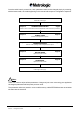
4. OPERATING MODES The default operating mode of the IS1000 is the "Simple Acknowledgment". Other operating modes can be selected by using the following sequence: Read the code Start of Configuration bottom left of each page Select the desired operating mode Adjust the timers value Read the code End of Configuration bottom right of each page 4.1. Simple Acknowledgment SIMPLE ACKNOWLEDGMENT * • Timer T1 = 200 ms (default value). To configure it, see page 51.
4.2. Host System Acknowledgment HOST SYSTEM ACKNOWLEDGMENT ACK/NAK PROTOCOL ACTIVATED • Timer T1 = 200 ms (default value). To configure it, see page 51. • Timer T2 = 3 s (default value). To configure it, see page 52. • Timer T3 = 2 s (default value). To configure it, see page 52. 4.3. On File / Not On File ACTIVATED DISACTIVATED ON FILE / NOT ONFILE • Timer T1 = 200 ms (default value). To configure it, see page 51. • Timer T2 = 3 s (default value). To configure it, see page 52.
4.3.1. Setting the On File Character This function can be used to change the On File Character sends by the host. By default: Character ~ (7E hexa). ACCESS CODE ON FILE CHARACTER Enter the desired character using the Code 39 Full ASCII Table page 70 VALIDATION 4.3.2. Setting the Not On File Character This function can be used to change the Not On File Character sends by the host. By default: Character DEL (7F hexa).
4.4. Bell ACTIVATED DISACTIVATED BELL • Timer T1 = 200 ms (default value). To configure it, see page 51. • Timer T2 = 3 s (default value). To configure it, see page 52.
4.5. Setting the Timers Operating Mode Default Value Timer T1 Timer T2 Timer T3 Simple Acknowledgment 200 ms Host System Acknowledgment 200 ms 3s 2s On File / Not On File 200 ms 3s 2s Bell 200 ms 3s 4.5.1.
4.5.2. Timer T2 Default value = 3 s ACCESS CODE TIMER T2 Enter the desired value using the Numeric Pad page 81 (Step of 100 ms) 10 ≤ value ≤ 254 VALIDATION 4.5.3.
5.
START OF CONFIGURATION IS1000 – Configuration Guide END OF CONFIGURATION 54
6. APPENDIXES 6.1. Radio Parameters 6.1.1. Radio Channel Channel Number Frequency 1 433.4 MHz 2 433.6 MHz 3 433.8 MHz 4 434.0 MHz 5 434.2 MHz 6 434.
6.1.2. Number of Re-transmissions Maximum number of bar code re-transmission attempts by the IS1000.
6.2. Adjustment of the Beep Sound 6.2.1. Laser Reader VOLUME LOW VOLUME HIGH * 6.2.2.
6.3. Preamble / Postamble One or several characters (22 maximum) can be systematically added to each message as Preamble (leading positions) or as Postamble (ending positions) before transmission to the host system. These characters can be chosen from the Code 39 Full ASCII Table (see appendix 6.10, page 70) when ASCII characters are required or from the Code 39 Full ASCII Extended Table (see appendix 6.8, page 65) to emulate function keys in Keyboard-Wedge mode. 6.3.1.
6.4. Conversion of Characters 6.4.1. First Character A first character can be converted into another defined by the user with the codes on this page (see next page for changing a second one). Example: The user wants to convert all Q characters found in an input message into A. Input message Q10Q234 will be changed into output message A10A234.
Read this code to clear a pre-programmed conversion of a first character.
6.4.2. Second Character ACCESS CODE SECOND CHARACTER TO BE CONVERTED Enter the desired character using the Code 39 Full ASCII Table page 70 VALIDATION ACCESS CODE NEW CHARACTER DESIRED Enter the desired character using the Code 39 Full ASCII Table page 70 VALIDATION Read this code to clear a pre-programmed conversion of a second character.
6.5. Rolling Buffer Mode In this mode, the input data is first stored in the buffer of the decoder (up to 3K characters maximum) and transmitted to the host system at a rhythm fixed by the inter-message timeout selected on this page.
6.6. Transmission of the Full ASCII Character Set This function releases the transmission of the 96 printable ASCII characters (20 to 7F hexa) to the host system in any communication mode. The purpose of this function is to verify that all characters are correctly emulated by the decoder specially in Keyboard-Wedge mode.
6.7. Displaying the Firmware Level Once the IS1000 radio base is connected to a host system with communication parameters correctly adjusted, the level of the firmware implemented in the IS1000 laser reader, radio base and its decoder can be displayed. LASER READER AND RADIO BASE The message will appear as follow: Portable=X.XX - - Base=X.XX RADIO BASE DECODER The message will appear as follow: FIRMWARE LEVEL: XXX.
6.8.
●N ●O F1 F2 ●P ●Q F3 F4 ●R ●S F5 F6 ●T ●U F7 F8 ●V ●W F9 F10 ●X ●Y F11 F12 ●Z RESERVED IS1000 – Configuration Guide 66
6.9.
IS1000 – Configuration Guide F G H I J K L M N O P Q R S T U 68
IS1000 – Configuration Guide V W X Y Z - .
6.10. Code 39 Full ASCII Table Translation and values of the bar codes which appear on the next pages. ASCII Code 39 Hexa Value ASCII Code 39 Hexa Value NUL %U 00 SP Space 20 SOH $A 01 ! /A 21 STX $B 02 " /B 22 ETX $C 03 # /C 23 EOT $D 04 $ /D 24 ENQ $E 05 % /E 25 ACK $F 06 & /F 26 BEL $G 07 ' /G 27 BS $H 08 ( /H 28 HT $I 09 ) /I 29 LF $J 0A * /J 2A VT $K 0B + /K 2B FF $L 0C , /L 2C CR $M 0D - - 2D SO $N 0E . .
Translation and values of the bar codes which appear on the next pages.
NUL SOH STX ETX EOT ENQ ACK BEL BS HT LF VT FF CR SO SI IS1000 – Configuration Guide 72
DLE DC1 DC2 DC3 DC4 NAK SYN ETB CAN EM SUB ESC FS GS RS US IS1000 – Configuration Guide 73
SP ! " # $ % & ' ( ) * + , - .
IS1000 – Configuration Guide 0 1 2 3 4 5 6 7 8 9 : ; < = > ? 75
@ A B C D E F G H I J K L M N O IS1000 – Configuration Guide 76
IS1000 – Configuration Guide P Q R S T U V W X Y Z [ \ ] ^ _ 77
IS1000 – Configuration Guide ` a b c d e f g h i j k l m n o 78
IS1000 – Configuration Guide p q r s t u v w x y z { l } ~ DEL 79
Page intentionally left blank IS1000 – Configuration Guide 80
6.11. Numeric Pad For entering variable data while configuration.
6.12.
UPC E UPC A UPC A with ADD-ON of 5 characters EAN 8 EAN 13 EAN 13 with ADD-ON of 5 characters IS1000 – Configuration Guide 83
Page intentionally left blank IS1000 – Configuration Guide 84