IS4813, IS4815, IS4823, and IS4825 Single-Line Laser Scan Engine Integration Guide
Disclaimer Metrologic Instruments Inc. (Metrologic) reserves the right to make changes in specifications and other information contained in this document without prior notice, and the reader should in all cases consult Metrologic to determine whether any such changes have been made. The information in this publication does not represent a commitment on the part of Metrologic.
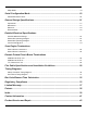
Table of Contents Introduction Product Overview ...........................................................................................................................................1 Models and Accessories Non-Decode Engines................................................................................................................................2 Decode Engines........................................................................................................................................
Sleep Mode...................................................................................................................................................18 Serial Configuration Mode......................................................................................... 19 Abbreviated ASCII Table ..............................................................................................................................20 General Design Specifications..................................................
Introduction Product Overview The non-decode IS4813 and IS4815 laser scan engines are designed for direct integration into custom OEM devices equipped with a decoder. The engine’s small size is ideal for integration into mobile computers, handheld scanners, medical/diagnostic equipment, mobile printers, lottery terminals, ATMs and access control devices.
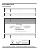
Models and Accessories Non-Decode Engines Options Model IS4813 IS4815 Description Non-Decode, 3.3VDC Scan Engine Non-Decode, 5VDC Scan Engine Accessories Part Number 19-07335 Description Flex Cable, 10-POS, 67.5 mm Length Decode Engines Options Base Model IS4823 IS4825 Description 3.3VDC Scan Engine with Decode PCB 5VDC Scan Engine with Decode PCB Model and Kit Delineation Figure 1.
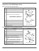
Components of the IS4800 Engine Series IS4813 and IS4815 Non-Decode Engine Item Description 1 Pin Locator Holes (see page 6) 2 Threaded Mounting Points (see page 6) Item Location Exit Beam Location, Laser Light Aperture 3 AVOID EXPOSURE! – LASER LIGHT IS EMITTED FROM THIS APERTURE. 4 Flex Cable, 10-POS 5 ZIF Connector, 10-Pin 6 Printed Circuit Board and Shield 7 Die Cast Chassis Figure 3.
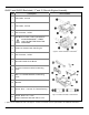
IS4823 and IS4825 Bracketed (-1† and -2) Decode Engine Assembly Item Description 1 Flex Cable, 12-POS 2 Flex Cable, 10-POS 3 ZIF Connector, 10-PIN 4 Exit Beam Location, Laser Light Aperture AVOID EXPOSURE! – LASER LIGHT IS EMITTED FROM THIS APERTURE 5 IS4813 or IS4815 Laser Scan Engine Item Location Figure 5. IS4823-1/IS4825-1 Assembled† 6 ZIF Connector, 12-PIN 7 Decode Printed Circuit Board 8 0.10 Dia. Clearance Holes for Mounting, 2 Pls. 9 M2 x 0.4 Threaded Bosses for Mounting, 3 Pls.
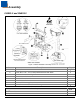
Assembly IS4823-2 and IS4825-2 Figure 7. IS4823-2/IS4825-2 Assembly Item 1 2 3 4 5 6 7 8 Description Bracket, Base Screw, M1.6 x 35 – 5 mm, Philips Stainless Steel with Patch IS4813 or IS4815 Scan Engine Flex Cable, 10-POS Decode Printed Circuit Board Flex Cable, 12-POS Bracket, PCB Locking Bar Screw, M1.2 – 6 mm, T3, Thread Forming Tools Required ® Torx Screw Driver Phillips Screw Driver Qty.
Mounting Specifications IS4813 and IS4815 Scan Engine Dimensions The engine has two M1.6 tapped holes on the bottom of the chassis for mounting the engine with screws. Two additional blind holes are provided on the bottom of the engine for keying purposes to assist with engine alignment (see figure below). Warning: The limited warranty (on page 37) is void if the following recommendations are not adhered to when mounting the IS4800 series laser scan engine.
IS4823 and IS4825 Bracketed (-1 and -2) Dimensions The engine bracket has three M2 x 0.4 threaded inserts on the bottom for mounting the assembly with screws. Two through holes are also provided as an alternative mounting method. Warning: The limited warranty (on page 37) is void if the following recommendations are not adhered to when mounting the IS4800 series laser scan engine. When securing the engine by utilizing the three M2 threaded inserts: • Use M2 x 0.
IS4823 and IS4825 (-0) Decode Printed Circuit Board Dimensions Warning: The limited warranty (on page 37) is void if the following recommendations are not adhered to when mounting the IS4800 series laser scan engine. When securing the decode board: • 3M™ 4032 1/32" double-coated urethane foam tape (or equivalent). • Use safe ESD practices when handling and mounting the decode board. Figure 10.
Exit Beam Specifications Figure 11. IS4800 Series Exit Beam Specifications See page see pages 12 - 15 for information on window material specifications and enclosure design considerations. Specifications are subject to change without notice.
Enclosure Specifications The IS4800 laser scan engine series was specifically designed for integration into custom housings for OEM applications. The scan engine’s performance will be adversely affected or permanently damaged when mounted in an unsuitable enclosure. Note: THIS DEVICE DOES NOT COMPLY WITH 21 CFR 1040. USE ONLY AS COMPONENT. The limited warranty (on page 37) is void if the following considerations are not adhered to when integrating an IS4800 series scan engine into a system.
Flex Cables Note: To ensure optimum engine stability, use the flex cables shipped with the scan engine. The host flex cable is used to carry power and data signals between the engine and the host system. The flex cable should allow for a minimal voltage drop and maintain a good ground connection between the host and the engine. In terms of grounding and voltage drop, a shorter cable is better.
Beam Clearance • Keep the scan engine’s beam sweep free from obstructions. For detailed information on the exit beam angle and location, please refer to Exit Beam Specifications on page 9. • A dark matte-finish on the internal walls of the housing can be utilized to avoid internal beam reflections. Output Window Properties Note: Contact a customer service representative to coordinate the best window material required to maintain laser safety requirements for your application.
Output Window Coatings • Anti-Reflection An anti-reflective coating can be applied to the inside and/or outside of the window to reduce the possibility of internal beam reflections interfering with the scan performance of the engine. If an antireflective coating is applied, it is recommended that it be on both sides of the window providing a 0.5% maximum reflectivity on each side from 640 to 690 nanometers at the nominal window tilt angle.
Minimum Allowable Window Position Required To Avoid Detrimental Internal Reflective Beam Interference at Positive Exit Beam Angle Tolerance +2.5° Minimum Projected Distance (mm) from the Engine’s Base to the Window’s Internal Surface (L) 5.0 +2.5° 10.0 14.5° +2.5° 15.0 10.5° +2.5° 20.0 8.0° +2.5° 25.0 7.0° +2.5° 30.0 6.5° +2.5° 35.0 6.0° +2.5° 40.0 5.5° +2.5° 45.0 5.0° +2.5° 50.0 5.0° Exit Beam Elevation Angle α Figure 12. Specifications are subject to change without notice.
Minimum Allowable Window Position Required To Avoid Detrimental Internal Reflective Beam Interference at Negative Exit Beam Angle Tolerance Exit Beam Depression Angle β Minimum Projected Distance (mm) from the Engine’s Base to the Window’s Internal Surface (M) Minimum Window Angle θ -2.5° 5.0 23.5° -2.5° 10.0 16.5° -2.5° 15.0 12.5° -2.5° 20.0 10.5° -2.5° 25.0 9.0° -2.5° 30.0 8.0° -2.5° 35.0 7.5° -2.5° 40.0 7.0° -2.5° 45.0 6.5° -2.5° 50.0 6.0° Figure 13.
Scan Engine Field of View and Depth of Field Field of View Distance from Engine Face Width of Field of View 50 mm (2") 57 mm (2.2") 254 mm (10") 264 mm (10.4") See page 9 for detailed information on the engine's exit beam specifications. Based on a .33 mm (13.0 mil) bar code. Figure 14. Typical Field of View Depth of Field vs. Minimum Bar Code Element Bar Code Element Width 1D Depth of Field* (In the Field of View) .13 mm 5.2 mil Start (From Engine Face) 70 mm (2.
Descriptions of IS4823 and IS4825 Operating Modes Activation Modes The following activation modes initiate the engine’s laser and motor drive circuitry for bar code scanning. Activate Scanning with the External Trigger (Default). An external I/O pin is used to enable the scanning cycle. A High-to-Low transition on the I/O signal is used to activate scanning. The signal must be deactivated (HIGH) and re-activated for subsequent scanning cycles.
Transmit “NO READ” Message on Laser Timeout If the scanning cycle terminates without scanning a bar code during the cycle, a “NO READ” message is transmitted with the termination of the scanning cycle. Activate the LED During the “NO READ” Transmission The LED is activated with the “NO READ” message. The LED is also activated after a successful scan. Enable RTS “NO READ” Pulse A configurable RTS pulse width transmitted after the “NO READ” message has been transmitted.
Serial Configuration Mode The IS4823/IS4825 can be configured by scanning configuration bar codes† or by serial commands sent from the host device. With serial configuration, each command sent to the engine is the ASCII representation of each numeral in the configuration bar code (see Figure 15). The entire numeric string is framed with an ASCII [stx] and an ASCII [etx]. Do Not Include in the Command ³ 1 0 0 1 0 4 Include in the Command Figure 15.
Example 2: The following sample illustrates the serial command sequence for configuring the engine for the factory default settings, disabling Code 128 scanning, and adding a “G” as a configurable prefix. Commands for features that require sequences of multiple bar codes for activation (i.e. prefixes, suffixes, and timeout features) should be sent in the same order that they are normally scanned.
General Design Specifications Operational Light Source: Visible Laser Diode (VLD) @ 650 nm Laser Power: 1 mW Depth of Scan Field: 50 mm – 254 mm (2" – 10") for 0.33 mm (13 mil) bar codes Width of Scan Field: 57 mm (2.2") @ 50 mm (2") from engine face 264 mm (10.4") @ 254 mm (10") from engine face Scan Speed: 100 Scan Lines per Second Typical Scan Pattern: Single Scan Line Minimum Bar Width: 0.10 mm (4.
Electrical IS4813 IS4815 Input Voltage: 3.3VDC ± 0.3VDC 5.0VDC ± 5% Power Consumption: 400 mW 350 mW Typical Operating Current: < 120 mA @ 3.3VDC < 70 mA @ 5.0VDC Standby Current: < 30 mA @ 3.3VDC < 15 mA @ 5.0VDC IS4823 IS4825 USB TTL USB TTL, RS232 Peak Operating Current: 170 mA 150 mA 135 mA 135 mA Idle Current: 75 mA 50 mA 72 mA 45 mA Sleep Current: 65 mA 5.5 mA 53 mA 15 mA Suspend Current (USB): 5.5 mA N/A 0.30 mA N/A Power Down Current (TTL): 5.
Detailed Electrical Specifications Absolute Maximum Ratings Signal * Signal Description Minimum Maximum Vinput † Voltage Applied to Any input pin (except D+ and D-) * -0.3V Vin Voutput Voltage Applied to Any output pin ** -0.3V Vin + 0.3V For USB version, Voltages on D+ and D- signal must conform to USB Specification ** Voutput must be less than 5.
IS4825 DC Operating Voltages Signal Minimum Maximum Operating Voltage 4.75V 5.25V VIH(1) Input High (RX, CTS) 2.5V VIL(1) Input Low (RX, CTS) VIH(2) Input High (TTL_INV, nWake) VIL(2) Input Low (TTL_INV, nWake) VIH(3) Input High (EXT. Trigger) VIL(3) Input Low (EXT. Trigger) VIN Signal Description Condition 0.8V 0.8 x Vin 0.8V 0.8 x Vin 0.8V VOH(1) Output High Voltage (TX,RTS) 0.
Scan Engine Terminations IS4813 Engine Connections 10-Pin ZIF Connector Figure 16. IS4813 Pin Signal Name Function 1 No Connect No Connect 2 Power, VCC 3.3V ± 0.
Decode Printed Circuit Board Terminations USB Decode PCB, 3.3V 12-Pin ZIF Connector Pin Signal Name Function 1 No Connect 2 +3.3V Power: Supply Voltage Input, +3.3V ± 0.3V 3 GND Ground: Power and Signal Ground 4 D- 5 6 D+ 7 Pin Function Reserved 8 PWRDWN Output: Active High = IS4823 is in Power Down Mode 9 nBEEPER Output: Active Low, Signal Capable of Sinking Current See Detailed Electrical Specifications starting on page 23.
USB Decode PCB, 5V 12-Pin ZIF Connector Pin Signal Name Function 1 No Connect 2 +5.0V Power: Supply Voltage Input, +5.0V ± 5% 3 GND Ground: Power and Signal Ground 4 D- 5 6 D+ 7 Pin Function Reserved 8 PWRDWN Output: Active High = Engine is in Power Down Mode 9 nBEEPER Output: Active Low, Signal Capable of Sinking Current See Detailed Electrical Specifications starting on page 23.
TTL, RS232, 3.3V / 5V 12-Pin ZIF Connector Pin Signal Name 1 TTLINV 2 Function Input: TTL RS232 Polarity Control with 33.2k ohm Pull-Up +3.3V or 5.0V Power: Supply Voltage Input, +3.3V ± 0.3V or +5.
Flex Cable Specifications and Installation Guidelines Figure 21. Flex Cable Specifications and Installation Guidelines Specifications are subject to change without notice.
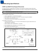
Timing Diagrams Startup Condition Timing Diagram The timing diagram below illustrates the correct power up procedure for the IS4813 and IS4815 engines. Scan Enable and Laser Enable are host driven signals. The Scan Enable and Laser Enable signals should be kept LOW (ON) at power up. Scan Control and Laser Control are engine driven signals. The engine's onboard microcontroller drives the Scan Control and Laser Control signals so the engine's laser will not turn ON before the scan mirror starts moving.
Scan Sense Timing Diagram The Scan Sense signal is a 50% duty cycle square wave with the transitions from HIGH to LOW indicating a change in the scan direction of the scanning beam (see Figure 22). Valid scan data occurs between the HIGH to LOW transitions. Figure 23 illustrates the condition in which power to the engine stays ON. Scan Enable and Laser Enable signals are controlled separately by the host.
Bar Code Element Time Calculation Realization of the full depth of field for all bar codes given in the specification is based on the ability of the decoding hardware to resolve a varying range of minimum element times. The minimum element time calculation for a given bar code size at a given distance is shown in Equation 1 (below). Minimum Element Time = (Element Size / Spot Speed) Equation 1. Example: Bar code Size = 5.2 mil Spot Speed @ 95 mm from face = 650 inches/second Minimum Element Time = (0.
Regulatory Compliance THIS DEVICE DOES NOT COMPLY WITH 21 CFR 1040. USE ONLY AS COMPONENT. The IS4800 Series Laser Scan engines are designed to meet the requirements of IEC Class 2 in accordance with IEC 60825-1:1993+A1:1997+A2:2001. IEC Class 2 is defined as follows: Emission Duration: Greater than 0.25 seconds Accessible Emission Limit: Less than 0.001 W (1.
United States Laser Safety To assist with the FDA filing requirements (refer to Regulatory Requirements), Metrologic has registered the scan engine with the FDA as a component. Customers can contact CDRH at the following address: Food and Drug Administration Center for Devices and Radiological Health Light Products Branch (HFX-312) Office of Compliance 2098 Gaither Road Rockville, MD 20850 Tel: 301-594-4654 www.fda.
Canada Laser Safety The Radiation Protection Bureau currently accepts products meeting the FDA standards in Canada. For more information contact: Radiation Protection Bureau 775 Brookfield Road Ottawa, Ontario K1A 1C1 EMC Products meeting FCC 47 CFR Part 15 will meet Industry Canada interference-causing equipment standard for digital apparatus, ICES-003. Additional testing is not required. A written notice indicating compliance must accompany the apparatus to the end user.
Caution Use of controls or adjustments or performance of procedures other than those specified herein may result in hazardous laser light exposure. Under no circumstances should the customer attempt to service the laser scanner. Never attempt to look at the laser beam, even if the scanner appears to be nonfunctional. Never open the scanner in an attempt to look into the device. Doing so could result in hazardous laser light exposure.
Limited Warranty The IS4800 series laser scan engines are manufactured by Metrologic at its Suzhou, China facility. The IS4800 series scan engines have a two (2) year limited warranty from the date of manufacture.
Patents Worldwide patents pending.
Index A G Accessories ........................................................... 2 Activate .................................................. See Modes ASCII ............................................................. 19, 20 Assignments pin ..................................................................... 25 Ground............................................................10, 25 B Beam aperture .............................................................. 9 clearance ..........................
Scan Speed ......................................................... 21 Screws ............................................................... 6–8 Serial Configuration ............................................. 19 Signals ................................................................. 23 V T Weight ..................................................................21 Window angle ............................................................13–15 coatings ...............................................
Contact Information The Americas (TA) Germany USA Tel: 49-89-89019-0 Fax: 49-89-89019-200 Email: info@de.metrologic.com Tel: 866.460.8033 (Customer Service) 888.633.3762 (Technical Support) 856.228.8100 (Corporate) Fax: 856.228.6673 (Sales) 856.228.1879 (Marketing) 856.228.0653 (Legal/Finance) Italy Tel: +39 0 51 6511978 Fax: +39 0 51 6521337 Email: info@it.metrologic.com Brazil Tel: 55.11.5185.8222 Fax: 55.11.5185.8225 Email: info@br.metrologic.
Product Service and Repair North America Suzhou Sales Office European Repair Center Tel: 800.436.3876 (Customer Service) 866.460.8033 (Customer Support) 888.633.3762 (Technical Support) Fax: 856.228.6673 (Sales) Email: info@metrologic.com Tel: 86-512-67622550 Fax: 86-512-67622560 Email: info@cn.metrologic.
Metrologic Instruments, Inc.