
Single-Line Laser Scan Engine Integration Guide


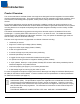
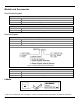
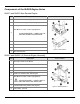
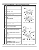
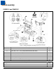
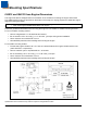
Table Of Contents
- IS4813, IS4815, IS4823 and IS4825
- Copyright/Trademarks
- Table Of Contents
- Introduction
- Assembly
- Mounting Specifications
- IS4813 and IS4815 Scan Engine Dimensions
- IS4823 and IS4825 Bracketed (-1 and -2) Dimensions
- IS4823 and IS4825 (-0) Decode Printed Circuit Board Dimensions
- Exit Beam Specifications
- Enclosure Specifications
- Electrostatic Discharge (ESD) Cautions
- Grounding
- Power Supply
- Power Sequencing
- Flex Cables
- Thermal Considerations
- Printed Circuit Board (PCB) Component Clearance
- Magnetic Sensitivity
- Airborne Contaminants and Foreign Materials
- Beam Clearance
- Output Window Properties
- Output Window Coatings
- Output Window Angle
- Minimum Allowable Window Position RequiredTo Avoid Detrimental Internal Reflective Beam Interference at Positive Exit Beam Angle Tolerance
- Minimum Allowable Window Position Required To Avoid Detrimental Internal Reflective Beam Interference at Negative Exit Beam Angle Tolerance
- Scan Engine Field Of View And Depth Of Field
- Descriptions Of IS4823 AND IS4825 Operating Modes
- Serial Configuration Mode
- General Design Specifications
- Detailed Electrical Specifications
- Scan Engine Terminations
- Decode Printed Circuit Board Terminations
- Flex Cable Specifications And Installation Guidelines
- Timing Diagrams
- Bar Code Element Time Calculation
- Regulatory Compliance
- Limited Warranty
- Patents
- Index
- Contact Information
- MANUAL DATE CODE
6
Mounting Specifications
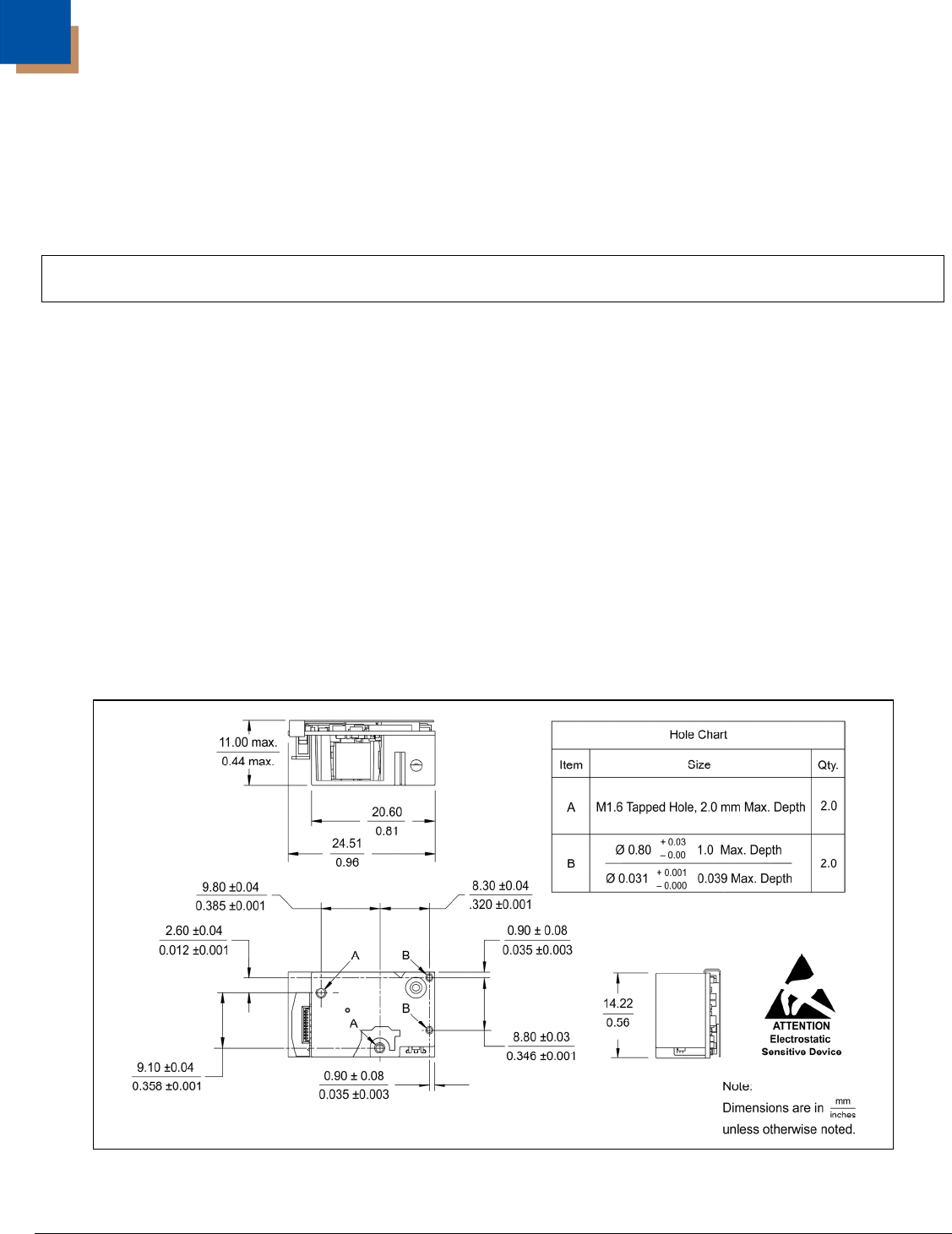
IS4813 and IS4815 Scan Engine Dimensions
The engine has two M1.6 tapped holes on the bottom of the chassis for mounting the engine with screws.
Two additional blind holes are provided on the bottom of the engine for keying purposes to assist with engine
alignment (see figure below).
Warning: The limited warranty (on page 37) is void if the following recommendations are not adhered to
when mounting the IS4800 series laser scan engine.
Follow the guidelines listed below when securing the engine to non-metallic or metallic mounting surfaces.
For a non-metallic mounting surface:
• Use non-magnetic M1.6 x .35 stainless steel screws.
• Do not exceed 1.35 ± .09 cm-kg [ 1.17 ± .08 in-lbs. ] of torque during screw installation.
• Use a minimum mount thickness of 3 mm.
• Use safe ESD practices when handling and mounting the engine.
For a metallic mounting surface:
• The die-cast engine chassis is at +Vcc. Use an insulator between the engine chassis and the host
(.005" thick PR4, or equivalent).
• Use non-metallic nylon or equivalent M1.6 x .35 screws.
• Do not exceeding 1.35 ± .09 cm-kg [ 1.17 ± .08 in-lbs. ] of torque.
• Use a minimum mount thickness of 3 mm.
• Use safe ESD practices when handling and mounting the engine.
Figure 8. IS4813 and IS4815 Engine Dimensions
Specifications are for reference only and are subject to change without notice.