
Single-Line Laser Scan Engine Integration Guide
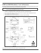
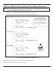
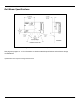
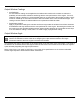
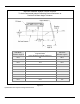
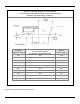
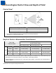
Table Of Contents
- IS4813, IS4815, IS4823 and IS4825
- Copyright/Trademarks
- Table Of Contents
- Introduction
- Assembly
- Mounting Specifications
- IS4813 and IS4815 Scan Engine Dimensions
- IS4823 and IS4825 Bracketed (-1 and -2) Dimensions
- IS4823 and IS4825 (-0) Decode Printed Circuit Board Dimensions
- Exit Beam Specifications
- Enclosure Specifications
- Electrostatic Discharge (ESD) Cautions
- Grounding
- Power Supply
- Power Sequencing
- Flex Cables
- Thermal Considerations
- Printed Circuit Board (PCB) Component Clearance
- Magnetic Sensitivity
- Airborne Contaminants and Foreign Materials
- Beam Clearance
- Output Window Properties
- Output Window Coatings
- Output Window Angle
- Minimum Allowable Window Position RequiredTo Avoid Detrimental Internal Reflective Beam Interference at Positive Exit Beam Angle Tolerance
- Minimum Allowable Window Position Required To Avoid Detrimental Internal Reflective Beam Interference at Negative Exit Beam Angle Tolerance
- Scan Engine Field Of View And Depth Of Field
- Descriptions Of IS4823 AND IS4825 Operating Modes
- Serial Configuration Mode
- General Design Specifications
- Detailed Electrical Specifications
- Scan Engine Terminations
- Decode Printed Circuit Board Terminations
- Flex Cable Specifications And Installation Guidelines
- Timing Diagrams
- Bar Code Element Time Calculation
- Regulatory Compliance
- Limited Warranty
- Patents
- Index
- Contact Information
- MANUAL DATE CODE
13
Output Window Coatings
• Anti-Reflection
An anti-reflective coating can be applied to the inside and/or outside of the window to reduce the
possibility of internal beam reflections interfering with the scan performance of the engine. If an anti-
reflective coating is applied, it is recommended that it be on both sides of the window providing a 0.5%
maximum reflectivity on each side from 640 to 690 nanometers at the nominal window tilt angle. The
coating must also meet the hardness adherence requirements of MIL-M-13508.
• Polysiloxane Coating
Apply a polysiloxane coating to the window surface to help protect the window from surface scratches
and abrasions that may interfere with the scan performance of the engine. Recessing the window into
the housing can also provided added protection against surface damage such as scratches and chips.
If an anti-reflective coating is used, there is no need to apply a polysiloxane coating.
Output Window Angle
Note: An improperly placed window has the serious potential to reduce the scan engine’s performance.
Careful consideration must be made when designing the output window’s distance and angle
placement relative to the scan engine’s exit beam and chassis.
It is important that angle of the window not be perpendicular to the exit beam of the scan engine. The angle of
the window can cause the beam’s laser light to reflect off the inside of the window back into the scan engine’s
optics ultimately degrading the engine’s performance.
Refer to the Figure 12 on page 14 and Figure 13 on page 15 for specifications on the minimum allowable
window angle required to avoid reflective beam interference.