
Single-Line Laser Scan Engine Integration Guide
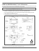
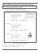
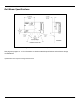
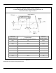
Table Of Contents
- IS4813, IS4815, IS4823 and IS4825
- Copyright/Trademarks
- Table Of Contents
- Introduction
- Assembly
- Mounting Specifications
- IS4813 and IS4815 Scan Engine Dimensions
- IS4823 and IS4825 Bracketed (-1 and -2) Dimensions
- IS4823 and IS4825 (-0) Decode Printed Circuit Board Dimensions
- Exit Beam Specifications
- Enclosure Specifications
- Electrostatic Discharge (ESD) Cautions
- Grounding
- Power Supply
- Power Sequencing
- Flex Cables
- Thermal Considerations
- Printed Circuit Board (PCB) Component Clearance
- Magnetic Sensitivity
- Airborne Contaminants and Foreign Materials
- Beam Clearance
- Output Window Properties
- Output Window Coatings
- Output Window Angle
- Minimum Allowable Window Position RequiredTo Avoid Detrimental Internal Reflective Beam Interference at Positive Exit Beam Angle Tolerance
- Minimum Allowable Window Position Required To Avoid Detrimental Internal Reflective Beam Interference at Negative Exit Beam Angle Tolerance
- Scan Engine Field Of View And Depth Of Field
- Descriptions Of IS4823 AND IS4825 Operating Modes
- Serial Configuration Mode
- General Design Specifications
- Detailed Electrical Specifications
- Scan Engine Terminations
- Decode Printed Circuit Board Terminations
- Flex Cable Specifications And Installation Guidelines
- Timing Diagrams
- Bar Code Element Time Calculation
- Regulatory Compliance
- Limited Warranty
- Patents
- Index
- Contact Information
- MANUAL DATE CODE
14
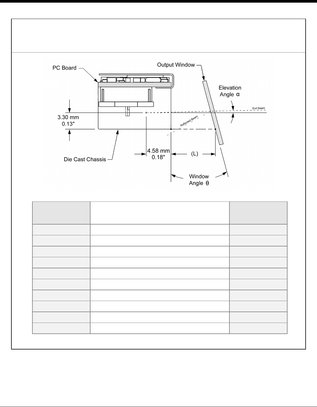
Minimum Allowable Window Position Required
To Avoid Detrimental Internal Reflective Beam Interference at
Positive Exit Beam Angle Tolerance
Exit Beam
Elevation Angle α
Minimum Projected Distance (mm) from the
Engine’s Base
to the Window’s Internal Surface (L)
Minimum
Window Angle θ
+2.5° 5.0 28.0°
+2.5° 10.0 14.5°
+2.5° 15.0 10.5°
+2.5° 20.0 8.0°
+2.5° 25.0 7.0°
+2.5° 30.0 6.5°
+2.5° 35.0 6.0°
+2.5° 40.0 5.5°
+2.5° 45.0 5.0°
+2.5° 50.0 5.0°
Figure 12.
Specifications are subject to change without notice.