
Single-Line Laser Scan Engine Integration Guide
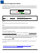
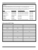
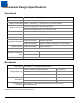
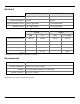
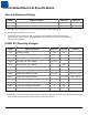
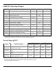
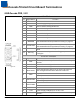
Table Of Contents
- IS4813, IS4815, IS4823 and IS4825
- Copyright/Trademarks
- Table Of Contents
- Introduction
- Assembly
- Mounting Specifications
- IS4813 and IS4815 Scan Engine Dimensions
- IS4823 and IS4825 Bracketed (-1 and -2) Dimensions
- IS4823 and IS4825 (-0) Decode Printed Circuit Board Dimensions
- Exit Beam Specifications
- Enclosure Specifications
- Electrostatic Discharge (ESD) Cautions
- Grounding
- Power Supply
- Power Sequencing
- Flex Cables
- Thermal Considerations
- Printed Circuit Board (PCB) Component Clearance
- Magnetic Sensitivity
- Airborne Contaminants and Foreign Materials
- Beam Clearance
- Output Window Properties
- Output Window Coatings
- Output Window Angle
- Minimum Allowable Window Position RequiredTo Avoid Detrimental Internal Reflective Beam Interference at Positive Exit Beam Angle Tolerance
- Minimum Allowable Window Position Required To Avoid Detrimental Internal Reflective Beam Interference at Negative Exit Beam Angle Tolerance
- Scan Engine Field Of View And Depth Of Field
- Descriptions Of IS4823 AND IS4825 Operating Modes
- Serial Configuration Mode
- General Design Specifications
- Detailed Electrical Specifications
- Scan Engine Terminations
- Decode Printed Circuit Board Terminations
- Flex Cable Specifications And Installation Guidelines
- Timing Diagrams
- Bar Code Element Time Calculation
- Regulatory Compliance
- Limited Warranty
- Patents
- Index
- Contact Information
- MANUAL DATE CODE
26
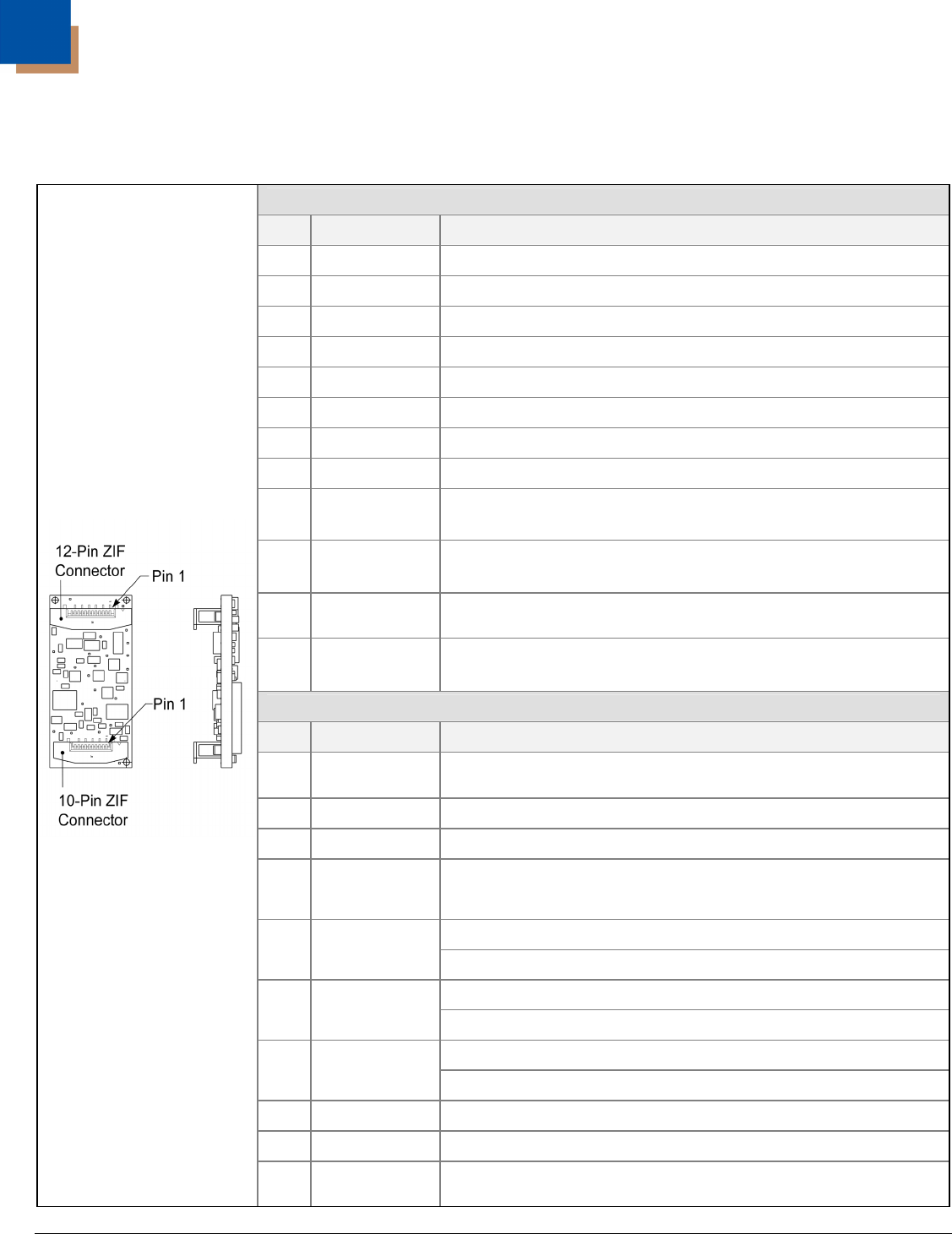
Decode Printed Circuit Board Terminations
USB Decode PCB, 3.3V
12-Pin ZIF Connector
Pin Signal Name Function
1 No Connect No Connection
2 +3.3V Power: Supply Voltage Input, +3.3V ± 0.3V
3 GND Ground: Power and Signal Ground
4 D- Input: USB D- Signal
5 <reserved> Pin Function Reserved
6 D+ Input: USB D+ Signal
7 <reserved> Pin Function Reserved
8 PWRDWN Output: Active High = IS4823 is in Power Down Mode
9 nBEEPER
Output: Active Low, Signal Capable of Sinking Current
See Detailed Electrical Specifications starting on page 23.
10 nGood Scan
Output: Active Low, Signal for Sinking Current (Good Scan)
See Detailed Electrical Specifications starting on page 23.
11 nEXT Wake
Input: Active Low, Wakes Engine From Suspend or Sleep
Mode
12 EXT Trig
Input: Active Low, Signal Used as Trigger Input to Activate
the Engine
10-Pin ZIF Connector
Pin Signal Name Function
1 SDA
I
2
C Data (Bi-Directional) – Devices Function as Auxiliary
Devices
2 GND Ground: Power and Signal Ground
3 GND Ground: Power and Signal Ground
4 Scan Sense
Level changes from High to low or low to high when the
laser changes direction at the start of the scan line
High = Bar
5 Data
Low = Space
High = Engine OFF
6 Scan Enable
Low = Engine ON
High = Laser OFF
7 Laser Enable
Low = Laser ON
8 NC No Connection
9 +3.3V Power: Supply Voltage Input, +3.3V ± 0.3V
Figure 18.
10 SCL
I
2
C Data (Bi-Directional) – Devices Function as Auxiliary
Devices