METROLOGIC INSTRUMENTS, INC.
Copyright © 2005 by Metrologic Instruments, Inc. All rights reserved. No part of this work may be reproduced, transmitted, or stored in any form or by any means without prior written consent, except by reviewer, who may quote brief passages in a review, or provided for in the Copyright Act of 1976. Products and brand names mentioned in this document are trademarks of their respective companies.
TABLE OF CONTENTS Introduction........................................................................................................... 1 Scanner and Accessories..................................................................................... 2 Installing the Scanner to the Host (Standard Features) Single Holotrak® Installation ............................................................................. 3 Holotrak® Primary/Secondary Installation .......................................................
iii
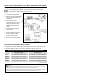
INTRODUCTION Metrologic's IS8000 series scanners bring the benefits of holography to longrange industrial bar code scanning. Enclosed in rugged NEMA-12 cases for industrial environments, the IS8000 series provides omnidirectional scanning with optional no code/wrong code warning. They can be mounted in any orientation and are capable of primary/secondary setup for added versatility. There are several IS8000 models to choose from depending on the scanning application.
SCANNER AND ACCESSORIES The following is a list of parts included in a standard IS8000 kit: ¾ IS8000 Series HoloTrak® Holographic Scanner ¾ Power Supply ¾ ¾ [MLPN 46-46207-US] 12VDC @ 4.16 Amps, 220VAC or ¾ [MLPN 46-46207-UK] 12VDC @ 4.16 Amps, 240VAC or ¾ [MLPN 46-46207-EC] 12VDC @ 4.16 Amps, 120VAC Communication Cable ¾ ¾ [MLPN 52-52702] Standard 2 meter (6 ft.
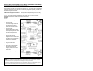
INSTALLING THE SCANNER TO THE HOST (STANDARD FEATURES) Single HoloTrak® Installation To avoid potential problems, do not power up the scanner until the communication cable is secured to the host. 1. Turn off the host system. 2. Connect the communications ® cable to the HoloTrak and to the host. 3. Check the AC input requirements of the power supply to make sure the voltage matches the AC outlet. 4. Plug the power supply to the scanner. 5.
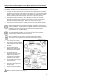
INSTALLING THE SCANNER TO THE HOST (STANDARD FEATURES) Primary/Secondary setup continued from previous page. All equipment must be connected before power-up. After both units complete the power-up diagnostics, the operator will need to program the primary unit with the MetroSet Program provided. Additional Equipment needed: Primary/Secondary Cable [MLPN 52-52707] To avoid potential problems, do not power up the scanner until the communication cable is secured to the host. 1. Turn off the host system.
INSTALLING THE SCANNER TO THE HOST (OPTIONAL FEATURES) Industrial Controller MX001 Interface Option The MX001 Industrial Control Interface performs three functions. ¾ Through an object sensor input, the scanner can be alerted to any package present in the scan field. The sensor must have a 12V or 5V at 10mA output signal or switch closure (relay) output. The MX001 can also supply 12VDC power at 200mA (max) to the sensor.
INSTALLING THE SCANNER TO THE HOST (OPTIONAL FEATURES) External Speaker Box Option When attached, beeper tones from the scanner are emitted from both the scanner speaker and external speaker to serve as an audible indication of the operation of the scanner. There are 6 beeper options available: ¾ Normal Tone ¾ Tone 2 ¾ Tone 1 ¾ Tone 3 ¾ Tone 4 ¾ No Tone ® Beeper tones can be adjusted by using the MetroSet program.
INSTALLING THE SCANNER TO THE HOST (OPTIONAL FEATURES) Hand-held Port Option A Non-Decode Hand-Held Scanner can be connected to an IS8000 series fixed scanner. To avoid potential problems, do not power up the scanner until the communication cable is secured to the host. 1. Turn off the host system. 2. Connect the communications cable ® to the HoloTrak and to the host. 3. Connect the communication cable of the hand-held scanner to the HoloTrak. 4.
CONFIGURATION TO THE HOST SYSTEM The scanner is shipped from the factory configured to a set of default conditions noted in the Default Settings section of this guide. In order for the scanner to communicate with the host system, it will need to be properly configured. Since each host system is unique, the scanner must be configured to match the host system requirements. Use the MetroSet®2 Scanner Configuration Program provided to configure the scanner.
INSTALLING AND RUNNING THE METROSET®2 PROGRAM How to Start To avoid potential problems, do not power up the scanner until the communication cable is secured to the host. 1. Turn off the PC after installing the MetroSet 2 program. 2. Connect the communication cable to the scanner and to the RS-232C serial port (COM1 or COM2) located on the PC. 3. Check the AC input requirements of the transformer to make sure the voltage matches the AC outlet.
PARTS OF THE SCANNER c Green and Red LEDs The red LED is on when the unit is done power up, the VLD is emitting light and the unit is ready to scan. The green LED flashes when the scanner has read a bar code successfully. The functions of the LED's can be reversed through special configuration with the MetroSet®2 configuration program. See the Visual and Audible Indicators section of this guide for more details. d Speaker The speaker is configured to emit a beep when a bar code has been transmitted.
MOUNTING BRACKET INSTALLATION 1. Locate the mounting bolts on the sides of the scanner. 2. Align the bolts on the scanner with the channels on the mounting bracket. 3. Slide the unit into place until the scanner bolts sit securely in the bottom of the channels. 4. Rotate the unit to the desired angle and secure into place with a locking bolt in the lower slot. 5. Tighten both bolts to secure the scanner in place.
VISUAL AND AUDIBLE INDICATORS When the scanner is on, the activity of the red and green LEDs indicate the status of the scanner. Flashing Red, No Green During power-up and diagnostic mode. Steady Red, No Green Unit has completed power-up, the VLD is emitting light, and the unit is ready to scan. Steady Red, Green Flash When the scanner transmits a successful read, the green LED will flash. Generally, if the green LED does not flash, then the bar code has not been successfully read.
LABELS A – B C D 13
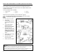
DEPTH OF FIELD AND SCAN PATTERN CHARACTERISTICS IS8300 Depth of Field and Scan Pattern The depth of field area defined is based conservatively on a 0.25 mm/0.010” bar code width. Actual scan areas will vary by label size and application.
DEPTH OF FIELD AND SCAN PATTERN CHARACTERISTICS IS8400 Depth of Field and Scan Pattern The depth of field area defined is based conservatively on a 0.33 mm/0.013” bar code width. Actual scan areas will vary by label size and application.
DEPTH OF FIELD AND SCAN PATTERN CHARACTERISTICS IS8500 Depth of Field and Scan Pattern The depth of field area defined is based conservatively on a 0.33 mm/0.013” bar code width. Actual scan areas will vary by label size and application.
DEPTH OF FIELD AND SCAN PATTERN CHARACTERISTICS IS8800 Depth of Field and Scan Pattern The depth of field area defined is based conservatively on a 0.33 mm/0.013” bar code width. Actual scan areas will vary by label size and application.
MAINTENANCE Smudges and dirt can interfere with the proper scanning of a bar code. Therefore, the output window will need occasional cleaning. 1. Spray optical quality cleaning fluid onto lint free, nonabrasive cleaning cloth. 2. Gently wipe the output window. Do not use solvents like alchohol or acetone. These materials can damage the window.
TROUBLESHOOTING GUIDE PROBLEM No LEDs POSSIBLE CAUSE(S) ACTION NEEDED No Power Check the power supply and outlet. No Scan Pattern No Power Alternating Red and Green LEDs flash with a razz tone. Motor Failure Contact a Metrologic service representative. The communication cable is not connected to the COM port. Check the communication cable connection at the host and scanner. The communication cable is damaged. Replace the communication cable. Scanner configuration settings have been lost.
APPENDIX A Design Specifications IS8800 IS8500 IS8400 IS8300 5 5 3 5 Optical Number of VLD Scan pattern Omni Omni Omni Omni Scan lines per second 5,600 5,600 3,360 5,250 Focal planes 4 4 4 5 Scan lines per focal plane 20 20 12 15 Total scan lines Minimum bar width 80 80 48 75 0.30 mm/0.012” 0.25 mm/0.010” 0.25 mm/0.010” 0.20 mm/0.008” Scan Area (Small Bar Widths) Bar width 0.33 mm/0.013” 0.33 mm/0.013” 0.33 mm/0.013” 0.25 mm/0.
APPENDIX A (CONTINUED) Design Specifications IS8800 IS8500 IS8400 IS8300 Input Voltage 12 VDC 12 VDC 12 VDC 12 VDC Starting Power 69 watts 69 watts 53 watts 53 watts Operating power 43 watts 43 watts 34 watts 34 watts EMC: FCC, ICES-003 & EN 55022 Class A Class A Class A Class A 658 nm ± 5 nm 658 nm ± 5 nm 658 nm ± 5 nm 658 nm ± 5 nm Laser power (peak) 7.7 mW 7.7 mW 7.7 mW 7.
APPENDIX B Default Settings Many functions of the scanner can be configured, or enabled/disabled. The factory programs the scanner to a set of default parameters. These defaults are marked with an asterisk (*) in the default column on the following pages. Unmarked parameters show the unavailability for that protocol. To speak with the host system properly, the scanner must be configured to match the systems individual requirements. Not all functions support all communication protocols.
APPENDIX B (CONTINUED) RS-232 RS-422 LIGHT PEN 200 msec to find Supps 9 9 9 Code 128 Coupon Option 9 9 9 Code 128 Coupon Conversion 9 9 9 PARAMETER DEFAULT 378/379 lock on supplement 9 9 9 Remote supplement required 9 9 9 9 9 9 9 9 9 Faster Beep/Same Tone 9 9 9 Lost Communication Timeout 3 beeps on timeout razz beep on timeout 5 retrys before timeout 9 9 9 Support 'D/E' disable/enable commands 9 9 Support 'F/L' laser off/on commands 9 9 Enable MECCA 9 9 9 9
APPENDIX B (CONTINUED) RS-232 RS-422 LIGHT PEN Fire triac if good read/match 9 9 9 Fire triac if bad match 9 9 9 Fire triac if no read 9 9 9 PARAMETER DEFAULT Triac Duration (sec.) 9 9 9 Delay Time before firing (sec.
APPENDIX B (CONTINUED) PARAMETER RS-232 RS-422 Transmit SANYO ID Chr 9 9 SNI Beetle Mode 9 9 9 9 French PC Term DEFAULT not currently supported Xon/Xoff handshaking 9 9 Programmable prefix identifiers 9 9 9 9 LIGHT PEN Xmit (dec) as 1st prefix identifier Xmit (dec) as 2nd prefix identifier Programmable suffix identifiers Xmit (dec) as 1st suffix identifier Xmit (dec) as 2nd suffix identifier LIGHT PEN FORMAT POLL SRC No/Yes No 9 Spaces/as scanned 9 HI/OUTPUT Bars/Code 39, Spaces/
APPENDIX B (CONTINUED) PARAMETER DEFAULT RS-232 RS-422 Transmit Code 39 Start/Stop Characters 9 9 Transmit ITF Mod 10 check digit 9 9 Transmit Code 39 Mod 43 check digit 9 9 9 9 LIGHT PEN SYMBOL LENGTH ITF(variable length-50 char) 14 char lock 9 Min 1-50 4 9 9 9 Lock 0-50 0 9 9 9 Normal 9 9 9 Flash 9 9 9 .5 secs 9 9 9 1 msec. 9 9 BEEPER TONE Normal, Alt1, Alt 2, Alt3, Alt4, None LED Flash/None Same Symbol Time Out .1, .2, .5, 1.25, 2.
APPENDIX C IS8000 Series Pinout Connections IS8400/IS8500/IS8800 DESCRIPTION Connector Type on Scanner DB25P (D-Type 25 Pin Male) Function: Communication Pinouts for RS-232/RS-422 and Light Pen Emulation. RS-232 Cable Note: Cables for RS-232 should leave the RS-422 pins unterminated at the scanner. RS-422 Cable Note: Cables for RS-422 should leave the RS-422 should leave the RS-232 transmit and receive pins unterminated at the scanner.
APPENDIX C IS8000 Series Pinout Connections IS8400/IS8500/IS8800 DESCRIPTION Connector Type on Scanner: DEC9P (D-Type 9-Pin Male) Function: Power Port DESCRIPTION Connector Type on Scanner: DEC9P (D-Type 9 Pin Male) Function: Hand Held Port (Low Speed Option) IS8300 PIN SIGNAL 1 2 3 5 4 6 7 8 9 12VDC Input Power to Scanner 12VDC Input Power to Scanner Earth Ground Power Ground Power Ground 12VDC Input Power to Scanner 12VDC Input Power to Scanner Power Ground Power Ground PIN SIGNAL 1 2 3 4 5
APPENDIX D Limited Warranty The IS8000 series scanners are manufactured by Metrologic at its Blackwood, New Jersey, U.S.A. facility. The IS8000 series scanners have a two (2) year limited warranty from the date of manufacture. Metrologic warrants and represents that all IS8000 series scanners are free of all defects in material, workmanship and design, and have been produced and labeled in compliance with all applicable U.S.
APPENDIX E Notices This equipment has been tested and found to comply with limits for a Class A digital device, pursuant to Part 15 of the FCC Rules. These limits are designed to provide reasonable protection against harmful interference when the equipment is operated in a commercial environment. This equipment generates, uses and can radiate radio frequency energy and, if not installed and used in accordance with the instruction manual, may cause harmful interference to radio communications.
APPENDIX E (CONTINUED) Achtung Die Verwendung anderer als der hier beschriebenen Steuerungen, Einstellungen oder Verfahren kann eine gefährliche Laserstrahlung hervorrufen. Der Kunde sollte unter keinen Umständen versuchen, den Laser-Scanner selbst zu warten. Sehen Sie niemals in den Laserstrahl, selbst wenn Sie glauben, daß der Scanner nicht aktiv ist. Öffnen Sie niemals den Scanner, um in das Gerät hineinzusehen. Wenn Sie dies tun, können Sie sich einer gefährlichen Laserstrahlung aussetzen.
APPENDIX F Patents "Patent Information This METROLOGIC product may be covered by one or more of the following U.S. Patents: U.S. Patent No.
INDEX A H ac input/outlet .............3-7, 9, 21, 28 accessories ...................................2 approvals......... 4, 13, 20, 21, 30, 31 assignments host ..... 3, 4, 5, 6, 7, 8, 9, 12, 19, 23 I indicators............................... 10, 12 input voltage....... 2-4, 21, 24, 27, 28 pin ................................ 10, 27, 28 audible............................... 6, 10, 12 B installation ................. 3, 5, 8, 11, 29 interfaces ........ 1, 10, 19, 21, 22, 27 L bar code ............
INDEX specifications.........................20, 21 V system interfaces .......... 1, 8, 20, 22 ventilation.................................... 21 T visual..................................... 10, 12 tones..............................................6 voltage ........................................ 21 transformers ..................................9 W troubleshooting............................19 warranty ...................................... 29 weight .........................................
CONTACT INFORMATION AND OFFICE LOCATIONS CORPORATE HEADQUARTERS NORTH AMERICA USA, New Jersey Metrologic Instruments, Inc. Tel: 1-800-ID-METRO Fax: 856-228-6673 Email: info@metrologic.com SOUTH AMERICA AND CENTRAL AMERICA Brazil São Paulo Metrologic do Brasil Ltda. Tel: 55-11-5182-8226 Fax: 55-11-5182-8315 Email: info@br.metrologic.com EUROPEAN, MIDDLE EAST & AFRICAN HEADQUARTERS Germany, Munich Metrologic Instruments GmbH Tel: 49-89-89019-0 Fax: 49-89-89019-200 Email: info@europe.metrologic.
March 2005 Printed in the USA 0 0 - 0 2 3 7 7 A