METROLOGIC INSTRUMENTS, INC.
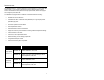
TABLE OF CONTENTS Introduction........................................................................................................... 1 Scanner and Accessories..................................................................................... 2 Before Installing Your MS7600............................................................................. 4 Mounting the MS7600 Series Option A: Shelf Support ....................................................................................
INTRODUCTION The MS7600 Horizon™ series is Metrologic’s next generation in-counter laser bar code scanner. This compact, hands-free scanner is designed with a dense 20-line omnidirectional scan pattern that helps provide fast, efficient throughput with a high first pass read rate.
SCANNER AND ACCESSORIES B ASIC K IT Part # Description Horizon™ Series Scanner MS7600 00-02407B MetroSelect® Programming Guide 00-02870B MS7600 Horizon Series Installation and User’s Guide 52-52511A 24” EAS cable Guides also available for download at www.metrologic.com. O PTIONAL A CCESSORIES Part # Description 46-46640 Point of Sale (POS) USB Plug 54-54xxx* Straight PowerLink Cable with built in power jack. 2.1 m (7') cord with short strain relief xxx* specifies connection to the host.
SCANNER AND ACCESSORIES (CONTINUED) O PTIONAL A CCESSORIES Part # Description AC to DC Power Transformer - Regulated 5.2V@650 mA output 45-45593 120V United States 45-45591 220V – 240V Continental European 45-45592 220V – 240V United Kingdom 46-46641 Stainless Steel Trim Ring R EPLACEMENT P ARTS Part # Description Window types (Sapphire, Everscan, and Standard) are not interchangeable due to laser safety and/or scanner performance differences.
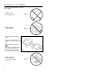
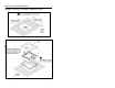
BEFORE INSTALLING YOUR MS7600 When mounting the MS7600 or replacing the Top Plate: DO NOT Turn the unit upside down. DO NOT Press on the window. Figure 1 Figure 2 Lift the Top plate straight up to remove. There is no hardware required to remove or replace the top cover. See caution on page 3. There are two installation tabs under the top cover that can be used to place the unit into the counter top mounting hole. DO NOT PRESS on the window in the replacement Top plate.
MOUNTING THE MS7600 SERIES There are three options for mounting your MS7600. Option “A” uses a shelf to support the unit. Option B lets the unit hang free in the counter top. Option C lets the unit hang free in the counter top with the use of a stainless steel trim ring for support. The trim ring (MLPN 46-46641) is an optional purchase. Contact a Metrologic customer service representative for details at 1-800-ID-METRO.
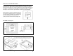
MOUNTING THE MS7600 SERIES OPTION B: Free Hanging Support Figure 8: Package Flow (right) Figure 9: Specifications for free hanging support.
MOUNTING THE MS7600 SERIES OPTION C: Trim Ring (MLPN 46-46641, Additional Purchase) Figure 11: Counter Top Opening for Trim Ring (MLPN 46-46641) Figure 12: Trim Ring (MLPN 46-46641) Installation 7
INSTALLATION FOR KEYBOARD W EDGE INTERFACE 1. Turn off the host system. 2. Disconnect the keyboard from the host. 3. Connect the PowerLink cable to the nd 2 jack from the top of the MS7600. 4. Connect the “Y” end of the PowerLink cable to the keyboard and the keyboard port on the host. If necessary use the male/female adapter cable supplied with the scanner for proper connections. Before continuing verify that the PowerLink cable is connected to the appropriate interface jack on the scanner.
INSTALLATION FOR STAND-ALONE KEYBOARD INTERFACE 1. Turn off the host system. 2. Disconnect the keyboard from the host. 3. Connect the PowerLink cable to the 2 jack from the top of the MS7600. 4. Connect the other end of the PowerLink cable to the keyboard port on the host. nd Before continuing verify that the PowerLink cable is connected to the appropriate interface jack on the scanner. An incorrect cable connection can cause communication problems or potential damage to the scanner. 5.
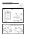
INSTALLATION FOR USB INTERFACE 1. Turn off the host system. 2. Determine if your application requires USB Keyboard communication protocols or USB Point of Sale communication protocols. 3. If you require USB Keyboard communication protocols, skip to step 4. If you require USB Point of Sale communication protocols: • • • Figure 16: POS Plug Installation Remove the MS7600 top cover. Insert the POS plug (MLPN 46-46640) into the slot indicated in Figure 16. Replace the top cover. 4.
INSTALLATION FOR USB INTERFACE Manufacturers Note: Plugging the scanner into the USB port of the PC does not guarantee that scanned information will appear at the PC. A software driver and correct configuration setting are also required for proper communication to occur. 6. 7. Scan the Enable USB Defaults bar code to configure the MS7600 for USB communication. Enable USB Defaults ³ 9 9 9 9 7 8 Turn on the host system.
INSTALLATION FOR RS232 OR LIGHT PEN INTERFACES 1. Turn off the host system. 2. Connect the PowerLink cable into st the 1 jack down from the top of the MS7600. 3. Connect the other end of the PowerLink cable to the host. Before continuing verify that the PowerLink cable is connected to the appropriate interface jack on the scanner. An incorrect cable connection can cause communication problems or potential damage to the scanner. 4.
INSTALLATION FOR RS232 OR LIGHT PEN INTERFACES Step 7, page 12 continued.
INSTALLATION FOR IBM 46XX INTERFACE 1. Turn off the host system. 2. Connect the MVC cable to the 1st jack down from the top of the MS7600. 3. Connect the other end of the MVC cable to the host. Before continuing verify that the MVC cable is connected to the appropriate interface jack on the scanner. An incorrect cable connection can cause communication problems or potential damage to the scanner.
INSTALLATION FOR OCIA INTERFACE 1. Turn off the host system. 2. Connect the MVC cable to the 2nd jack down from the top of the MS7600. 3. Connect the other end of the MVC cable to the host. Before continuing verify that the MVC cable is connected to the appropriate interface jack on the scanner. An incorrect cable connection can cause communication problems or potential damage to the scanner.
INSTALLATION OF A SECONDARY SCANNER 1. Turn off the host system. 2. Connect the round end of the PowerLink RS232 AUX cable [MLPN 54-54667A] to the RS232 jack of the secondary scanner (see figure 20). 3. Connect the other end of the PowerLink RS232 AUX cable into the 3rd jack down from the top of the MS7600. The following Metrologic scanners can be used in the “Aux” input of the MS7600: the MS9520, MS9540, MS7220, MS7120, MS6720, MS6220, MS6520, MS5145 or another MS7600.
INSTALLATION OF A SECONDARY SCANNER 11. Scan the following bar code to configure the auxiliary port on the MS7600 to accept a Metrologic scanner as the secondary scanner. The following bar codes do not apply when using an MS6720 as a secondary scanner. Contact a Metrologic representative for additional information on the MS6720. If the secondary scanner is not a Metrologic scanner refer to Section O of the MetroSelect Configuration Guide.
INSTALLATION OF A SECONDARY SCANNER Figure 20: Connector Orientation (Top) Secondary Scanner Setup (Bottom) 18
SCANNER PARTS q p ot o p n v s r Figure 21: Scanner Parts n o p q r s t u v u Output Window (Laser Aperture) Amber LED (Located Under Window) Red LED (Located Under Window) Speaker Cable Connection Area Stainless Steel Top (MS7625 units only) Package Flow Indicator Arrow Head Rubber Connector Plug EAS Deactivation Antenna Connector 19
MAINTENANCE Smudges and dirt can interfere with the proper scanning of a bar code. Therefore, the output window will need occasional cleaning. For the MS7600 glass window: 1. 2. Spray glass cleaner onto lint free, non-abrasive cleaning cloth. Gently wipe the scanner window. For the MS7600 red window: 1. 2. Use mild soap and water with lint free, non-abrasive cleaning cloth. Gently wipe the scanner window.
SCANNER LABELS Each scanner has a label on the bottom of the unit. The label contains information such as the model number, date of manufacture, serial number, and caution information. An additional caution label is located under the top plate. The following are examples of these labels.
AUDIBLE INDICATORS When the MS7600 scanner is in operation, it provides audible feedback. These sounds indicate the status of the scanner. Eight settings are available for the tone of the beep (normal, 6 alternate tones and no tone) plus three volume settings. To change the tone or volume, refer to the Changing the Beeper Tone & Volume section of this manual. One Beep When the scanner first receives power, the amber LED will turn on, the red LED will flash and the scanner will beep once.
VISUAL INDICATORS There is a red LED and amber LED on the front of the MS7600. When the scanner is on, the flashing or constant illumination of the LEDs indicates the status of the current scan and the scanner. Figure 24: LEDs No Red or Amber LED The LEDs will not be illuminated if the scanner is not receiving power from the host or transformer. Steady Amber When the laser is active, the amber LED is illuminated. The amber LED will remain illuminated until the laser is deactivated.
FAILURE MODES Figure 25: LEDs Flashing Amber and One Razzberry Tone This indicates the scanner has experienced a laser subsystem failure. Return the unit for repair at an authorized service center. Flashing Red and Amber and Two Razzberry Tones This indicates the scanner has experienced a motor failure. Return the unit for repair at an authorized service center.
CHANGING THE BEEPER TONE & VOLUME Changing the Beeper Tone Beeper tones may be programmed directly or incrementally using the following bar code. The new tone will be heard followed by a short pause. Two more new tones will be heard signifying the new setting has been stored in memory. The silent (no beep) tone is also selectable. Next Beep Tone ³ 9 9 9 9 7 5 Changing the Beeper Volume Volume levels may be programmed directly or incrementally using the following bar code.
POWER SAVE MODES AND IR DETECTION The MS7600 has five programmable power save modes. Refer to the MetroSelect Programming Guide for additional information on Power Save Modes. 1. Blink Power Save Mode: Blinks the laser OFF & ON after a programmed period of non-use. When the scanner recognizes a bar code it will exit the Blink mode. 2. Laser Off Power Save Mode: Turns the laser OFF after a programmed period of non-use. The motor continues to spin allowing for a faster “wake” up time.
POWER SAVE MODES AND IR DETECTION Figure 27: IR Activation Area Parallel to Package Flow Specifications are subject to change without notice.
SCAN VOLUME SPECIFICATIONS (BASED ON 100% UPC BAR CODES) Figure 28: Scan Volume in Plane Perpendicular to Flow Figure 29: Scan Volume in Plane Parallel to Flow Specifications subject to change without notice.
DEPTH OF FIELD BY MINIMUM BAR CODE ELEMENT W IDTH (BASED ON 100% UPC BAR CODES) Figure 30: Depth of Field Perpendicular to Flow Minimum Bar Code Element Width mm mils A .13 5.2 B .19 7.5 C .26 10.4 D .33 13 E .48 19 Specifications subject to change without notice.
TROUBLESHOOTING GUIDE The following guide is for reference purposes only. Contact a Metrologic representative at 1-800-ID-METRO or 1-800-436-3876 to preserve the limited warranty terms. MS7600 SERIES TROUBLESHOOTING GUIDE SYMPTOMS POSSIBLE CAUSE(S) SOLUTION All Interfaces No LEDs, beep or motor spin. No power is being supplied to the scanner. Check transformer, outlet and power strip. Make sure the cable is plugged into the scanner. No LEDs, beep. No power is being supplied to the scanner from host.
TROUBLESHOOTING GUIDE (CONTINUED) SYMPTOMS POSSIBLE CAUSE(S) SOLUTION Scanning a particular symbology that is not enabled. UPC/EAN, Code 39, interleaved 2 of 5, Code 93, Code 128 and Codabar are enabled by default. Verify that the type of bar code being read has been selected. The scanner has been programmed for a character length lock, or a minimum length and bar code being scanned does not satisfy the programmed criteria. Verify that the bar code that is being scanned falls into the criteria.
TROUBLESHOOTING GUIDE (CONTINUED) SYMPTOMS POSSIBLE CAUSE(S) SOLUTION The bar code may have been printed incorrectly. Check if it is a check digit/character/or border problem. The scanner is not configured correctly for this type of bar code. Check if check digits are set properly. The minimum symbol length setting does not work with the bar code. Check if the correct minimum symbol length is set. Scanner beeps at some bar codes and NOT for others of the same bar code symbology.
TROUBLESHOOTING GUIDE (CONTINUED) SYMPTOMS POSSIBLE CAUSE(S) SOLUTION Everything works except for a couple of characters. These characters may not be supported by that country’s key look up table. Try operating the scanner in Alt mode. The unit is transmitting each character. Configuration is not correct. Increase the interscan code delay setting. Adjust whether the F0 break is transmitted. It may be necessary to try this in both settings. Alpha characters show as lower case.
TROUBLESHOOTING GUIDE (CONTINUED) SYMPTOMS POSSIBLE CAUSE(S) Characters are being dropped. Intercharacter delay needs to be added to the transmitted output. SOLUTION Add some intercharacter delay to the transmitted output by using the MetroSelect® Programming Guide (MLPN 00-02407A-1 & -2). Aux port operation with any interface Trouble with the Secondary Scanner. Refer to the user guide provided with the secondary scanner. Cable [MLPN 54-54667] may not be connected to the proper port.
DESIGN SPECIFICATIONS MS7600 SERIES DESIGN SPECIFICATIONS OPERATIONAL Light Source: VLD 650 ± 10 nm Laser Power: 1.1 mW maximum Depth of Field: 0 mm to 203.2 mm (0”- 8.0”) for 0.33 mm (13 mil) bar code Width of Scan Field: 85 mm (3.3”) @ 0 mm (0.0”); 142 mm (5.6”) @ 124 mm (4.9”) Scan Speed: Scan Pattern: Scan Lines: Min Bar Width: 2000 scans/second 5 fields of 4 parallel lines (omnidirectional) 20 0.127 mm (5.
DESIGN SPECIFICATIONS (CONTINUED) MS7600 SERIES DESIGN SPECIFICATIONS ELECTRICAL Input Voltage: Power: Operating Current: Standby Current: DC Transformers: Laser Class: EMC: 5.2VDC ± 0.25V 2.6 W 500 mA Laser Off Power Save Mode = < 350 mA Laser/Motor Off Power Save Mode = <165 mA Class II; 5.
RS232 DEMONSTRATION PROGRAM If an RS232 scanner is not communicating with your IBM compatible PC, key in the following BASIC program to test that the communication port and scanner are working. This program is for demonstration purposes only. It is only intended to prove that cabling is correct, the com port is working, and the scanner is working. If the bar code data displays on the screen while using this program, it only demonstrates that the hardware interface and scanner are working.
APPLICATIONS AND PROTOCOLS The model number on each scanner includes the scanner number and factory default communications protocol. SCANNER VERSION IDENTIFIER 7620 7625 13 RS232, IBM 46xx, OCIA, Aux 7620 7625 37 RS232, Light Pen, Keyboard Wedge, Stand-Alone Keyboard, USB, Aux COMMUNICATION PROTOCOL(S) The MS7600 with Built-in PC Keyboard Wedge Interface is designed to be used for keyboard emulation only.
DEFAULT SETTINGS Many functions of the scanner can be "programmed" - that is, enabled or disabled. The scanner is shipped from the factory programmed to a set of default conditions. The default parameter of the scanner has an asterisk ( * ) in the charts on the following pages. If an asterisk is not in the default column then the default setting is Off or Disabled. Every communication does not support every parameter.
DEFAULT SETTINGS (CONTINUED) PARAMETER DEFAULT OCIA RS-232 LIGHT PEN Bars High as Scanned 9 Spaces High as Scanned 9 KBW USB 9 DTS/SIEMENS DTS/NIXDORF IBM 46XX * 9 NCR F 9 NCR S 9 9 Poll Light Pen Source Normal 9 9 9 9 9 9 Beep/Transmit Sequence Before Transmit 9 9 9 9 9 9 Beeper Volume Loudest 9 9 9 9 9 9 None 9 9 9 9 9 9 Razzberry Tone on Timeout 9 9 9 9 9 9 Three Beeps on Timeout 9 9 9 9 9 9 * 9 9 9 9 9 9 10 mins.
DEFAULT SETTINGS (CONTINUED) DEFAULT OCIA RS-232 LIGHT PEN IBM 46XX KBW USB Number of Scan Buffers 1 9 9 9 9 9 9 Transmit EAN-8 Check Digit * 9 9 9 9 9 Transmit EAN-13 Check Digit * * 9 9 9 9 9 9 9 9 9 9 9 9 9 9 9 Expand UPC-E 9 9 9 9 9 9 Convert UPC-A to EAN-13 9 9 9 9 9 UPC GTIN-14 Format 9 9 Transmit Lead Zero on UPC-E 9 9 Convert EAN-8 to EAN-13 a a PARAMETER Transmit UPC-A Check Digit Transmit UPC-E Check Digit 9 9 9 9 9 9 9 9 a a
DEFAULT SETTINGS (CONTINUED) PARAMETER DEFAULT OCIA RS-232 LIGHT PEN IBM 46XX KBW USB UPC Suffix 9 9 9 Transmit AIM ID Characters 9 9 9 STX Prefix 9 9 9 ETX Suffix 9 9 9 Carriage Return * 9 9 9 Line Feed - disabled by default in KBW * 9 9 9 Tab Prefix 9 9 9 Tab Suffix 9 9 9 "DE" Disable Command 9 9 "FL" Laser Enable Command 9 9 DTR Handshaking Support 9 RTS/CTS Handshaking 9 Character RTS/CTS * 9 Message RTS/CTS 9 XON/XOFF Handshaking 9 ACK/NAK 9
DEFAULT SETTINGS (CONTINUED) OCIA RS-232 LIGHT PEN IBM 46XX KBW USB 9 9 as code 39 9 9 9 9 9 9 9 9 9 9 9 9 Suffix Characters 9 9 9 Prefixes for individual Code Types 9 9 9 9 9 9 9 9 9 PARAMETER DEFAULT Coupon Code 128 Programmable Code Lengths 7 avail. Programmable Prefix Characters 10 avail. 9 Editing Inter Scan-Code Delay Programmable (100 µsec steps) 9 9 9 800 µsec Function/Control Key Support Minimum Element Width Programmable in 5.
DEFAULT SETTINGS (CONTINUED) Default settings for “Aux” interface The secondary scanner and the MS7600 always communicate via RS232. Data is relayed to the host via various primary interfaces.
SCANNER AND CABLE TERMINATIONS Scanner Pinout Connections The MS7600 scanner interfaces terminate to 10-pin modular jacks located on the back of the unit. The serial # label indicates the model number of the scanner.
SCANNER AND CABLE TERMINATIONS (CONTINUED) Figure 32: Scanner Interface Ports MS762x-37 Keyboard Wedge, Stand-Keyboard or USB Pin 1 2 3 4 5 6 7 8 9 10 46 Function Ground USB DUSB D+ PC Data PC Clock KB Clock PC +5V, V-USB KB Data +5VDC Shield Ground MS762x-37 RS-232 or Light Pen Pin 1 2 3 4 5 6 7 8 9 10 Function Ground RS-232 Transmit Output RS-232 Receive Input RTS Output CTS Input DTR Input/LTPN Source N/C LTPN Data +5VDC Shield Ground
SCANNER AND CABLE TERMINATIONS (CONTINUED) Cable Connector Configurations (Host End) PowerLink Cable MLPN 54-54xxx* Pin 1 2 3 4 5 6 7 8 9 Function Shield Ground RS-232 Transmit Output RS-232 Receive Input DTR Input Power/Signal Ground Reserved CTS Input RTS Output +5VDC xxx* specifies connection to the host USB PowerLink Cable (MLPN 54-54165, Type A) Pin 1 2 3 4 Function N/C DD+ Ground 5 6 1 9-Pin D-Type Conn.
SCANNER AND CABLE TERMINATIONS (CONTINUED) Cable Connector Configuration The PowerLink cable is terminated with a 5-pin DIN female connector on one end, and a 6-pin mini DIN male on the other. 4 2 1 5 2 3 1 4 3 6 5 PowerLink Cable 5-Pin DIN, Female 6-Pin DIN, Male Metrologic will supply an adapter cable with a 5-pin DIN male connector on one end and a 6-pin mini DIN female connector on the other.
LIMITED W ARRANTY The MS7600 Series scanners are manufactured by Metrologic at its Blackwood, New Jersey, U.S.A. facility. The MS7600 Series scanners have a two (2) year limited warranty from the date of manufacture. Metrologic warrants and represents that all MS7600 Series scanners are free of all defects in material, workmanship and design, and have been produced and labeled in compliance with all applicable U.S.
NOTICES This device complies with Part 15 of the FCC Rules. Operation is subject to the following two conditions: (1) This device may not cause harmful interference, and (2) this device must accept any interference received, including interference that may cause undesired operation. This equipment has been tested and found to comply with the limits for a Class B digital device, pursuant to Part 15 of the FCC rules.
NOTICES (CONTINUED) Attention L'emploi de commandes, réglages ou procédés autres que ceux décrits ici peut entraîner de graves irradiations. Le client ne doit en aucun cas essayer d'entretenir lui-même le scanner ou le laser. Ne regardez jamais directement le rayon laser, même si vous croyez que le scanner est inactif. N'ouvrez jamais le scanner pour regarder dans l'appareil. Ce faisant, vous vous exposez à une rayonnement laser qú êst hazardous.
PATENTS “Patent Information This METROLOGIC product may be covered by one or more of the following U.S. Patents: U.S. Patent No.
INDEX A Accessories .................................. 2 Adapter ....................................... 48 Audible........................................ 22 Autodiscriminates ....................... 35 B Bar Code .............................. 28, 29 Beep ..................................... 22, 40 C Cable .......... 2, 12, 19, 33-35, 45-48 Caution ................... 8-10, 12, 14-16 Ce ......................................... 50, 51 Communication..................... 38, 40 Connector ..................
INDEX T Termination................................. 35 Transformers .............................. 36 Troubleshooting ...30, 31, 32, 33, 34 V Ventilation ...................................36 Visual ..........................................23 Voltage .....................................8-16 U USB ............................................ 10 W Warranty......................................49 Weight .........................................
August 2002 Printed in the USA 00 - 02870B