LOCATIONS CORPORATE HEADQUARTERS North America Metrologic Instruments, Inc. 90 Coles Road Blackwood, NJ 08012-4683 Customer Service: 1-800-ID-METRO Tel: 856-228-8100 Fax: 856-228-6673 Email: info@metrologic.com Internet: www.metrologic.com EUROPEAN HEADQUARTERS Germany, Middle East and Africa Metrologic Instruments GmbH Dornierstrasse 2 82178 Puchheim b. Munich, Germany Tel: +49 89 89019 0 Fax: +49 89 89019 200 Email: info@europe.metrologic.com Germany Email: info@de.metrologic.
TABLE OF CONTENTS Introduction........................................................................................................... 1 Scanner and Accessories..................................................................................... 2 Operation Test...................................................................................................... 4 Installing the Scanner to the Host System MS9524-00/9/11/14/41 and MS9544-00/9/11/14/41.........................................
INTRODUCTION The VoyagerPDF™ series of scanners has taken the already proven and reliable Voyager series to new levels of ability. With its introduction, Metrologic’s VoyagerPDF™ series has added the ability to decode PDF, a 2D symbology that includes both normal and truncated version of this bar code type. This symbology differs from normal 1D barcodes and can be viewed as a series of 1D segments arranged vertically.
SCANNER AND ACCESSORIES BASIC KIT Part # Description MS9524 or MS9544 VoyagerPDF Series Scanner 00-02544 MetroSelect Single-Line Programming Guide* 00-02990 Supplemental Programming Guide* 00-02989 MS9524/44 VoyagerPDF Series Installation and User’s Guide* * Available on the Metrologic website - www.metrologic.com OPTIONAL ACCESSORIES Part # Description AC to DC Power Transformer- Regulated 5.2VDC @ 650 mA output.
SCANNER AND ACCESSORIES OPTIONAL ACCESSORIES Part # Description 53-53213 USB Power/Communication Cable, 3 m (10’) coiled cord, long strain relief, gray 53-53214 USB Power/Communication Cable, 5 m (17’) coiled cord, long strain relief, gray MX009-3** MX009 USB Converter Cable MVC** Metrologic Voltage Converter Cable +12VDC to +5.2VDC or -12VDC to +5.
OPERATIONAL TEST 1. Connect the 10-pin RJ45 male connector into the jack on the VoyagerPDF. You will hear a ‘click’ when the connection is made. 2. Connect the L-shaped plug of the power supply into the power jack on the PowerLink cable. 3. Connect the power supply into an AC outlet. Make sure the AC input requirements of the power supply match the AC outlet. 4. 5. When the VoyagerPDF is ready to scan, the blue LED will turn on, the white LED will flash and the scanner will beep once.
INSTALLING THE SCANNER TO THE HOST SYSTEM MS9524-00/9/11/14/41 and MS9544-00/9/11/14/41 1. Turn off the host system. 2. Connect the 10-pin RJ45 male connector into the jack on the VoyagerPDF. You will hear a ‘click’ when the connection is made. 3. Connect the L-shaped plug of the power supply into the power jack on the PowerLink cable. 4. Make sure the AC input requirements of the power supply match the AC outlet. Connect the power supply into an AC outlet.
INSTALLING THE SCANNER TO THE HOST SYSTEM Keyboard Wedge MS9524-47 and MS9544-47 1. Turn off the PC. 2. Connect the 10-pin RJ45 male connector into the jack on the VoyagerPDF. You will hear a ‘click’ when the connection is made. 3. Connect the L-shaped plug of the power supply into the power jack on the PowerLink cable. 4. Make sure the AC input requirements of the power supply match the AC outlet. Connect the power supply into an AC outlet.
INSTALLING THE SCANNER TO THE HOST SYSTEM Stand Alone Keyboard 1. Turn off the host system. 2. Connect the 10-pin RJ45 male connector into the jack on the VoyagerPDF. You will hear a ‘click’ when the connection is made. 3. Connect the L-shaped plug of the power supply into the power jack on the PowerLink cable. 4. Make sure the AC input requirements of the power supply match the AC outlet. Connect the power supply into an AC outlet. The outlet should be near the equipment and easily accessible. 5.
INSTALLING THE SCANNER TO THE HOST SYSTEM Integrated Full Speed USB MS9524-40 and MS9544-40 1. Turn off the host system. 2. Connect the 10-pin RJ45 male connector of the USB cable into the jack on the VoyagerPDF. You will hear a ‘click’ when the connection is made. 3. Connect the other end of the USB cable to the host USB port. 4. Turn on the host system. Plugging the scanner into a port on the host system does not guarantee that scanned information will be communicated properly to the host system.
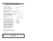
DISCONNECTING THE POWERLINK CABLE Before removing the cable from the scanner, Metrologic recommends that the power on the host system is off and the power supply has been disconnected from the PowerLink cable. Figure 8. 1. Locate the small ‘pin-hole’ on the top of the unit near the bottom of the Voyager logo. 2. Bend an ordinary paperclip into the shape shown above. 3. Insert the paperclip (or other small metallic pin) into the small ‘pin-hole’. 4. You will here a faint ‘click’.
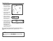
HOW TO USE CODEGATE – MS9544 1 • Auto trigger activates the laser 2 • Place the laser line on the bar code 3 • Press the CodeGate button to transmit the data Figure 10. TWO MODES OF OPERATION • Auto-triggers while in the stand • Bar code is automatically decoded and transmitted Figure 11. • CodeGate activates when removed from the stand • Bar code data is transmitted when the CodeGate button is pressed Figure 12.
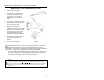
HOW TO SCAN PDF BAR CODES Operator Note: PDF-CodeGate is disabled (by default) in all MS9544 VoyagerPDF units. 1. The auto trigger activates the laser when the bar code is placed in the scanner's IR range. 2. Position the laser line at the top of the code then sweep the beam over and down to the base of the code. If needed, re-sweep the entire code, up and down. As segments of the code are scanned, an audible indicator will sound (default). Figure 13.
STAND KITS Free Standing Kits #46-46128 a. b. c. d. e. f. Stand (MLPN 36-00454).............................Qty 1 Apron (MLPN 50-50440).............................Qty 1 Screw, M3 x 6 mm (MLPN 18-18670) ........Qty 2 Washer, #5 x .5 OD (MLPN 18-18671) ......Qty 2 Stand Anchor (MLPN 50-50449) ................Qty 1 M3 x 20 mm Set Screw (MLPN 18-18672).Qty 1 c. a. d. b. e. f. Figure 15. Optional Hard Mount Accessory Kit #46-46351 a.
ASSEMBLING THE STANDS There are 2 options for assembling the stand. The first option allows the stand to be self-supporting and moved freely or placed anywhere on the countertop. The second option is used if the stand will be bolted/hard-mounted to the countertop. Stand Option 1: Self-supported For use with kit #46-46128 Step 1 Apron Slide the apron (MLPN 50-50440) over the stand (MLPN 36-00454). Stand Figure 19. Step 2 Apron Position the stand so it sits under the tab on the apron.
ASSEMBLING THE STAND (CONTINUED) Stand Option 2: Hard-mounted to countertop (continued) For use with kits #46-46128, #46-46351 and MS951 Stand Replacements Anchor from Kit #46-46128 Base Assembly from Kit #46-46351 or MS951 Stand Base Step 3 Screw the stand anchor (MLPN 50-50449) onto the base assembly until it sits flush. Figure 23. Step 4 Remove the logo plate on the stand by gently using an Exacto knife to release the plate hook. Figure 24. Step 5 Position the stand over the base assembly.
ASSEMBLING THE STAND (CONT.) Wall Mount, Option 1: For Kit #46-46433 or Kit #46-46508 Step 1: Drill two #39 pilot holes 3.00” apart. Step 2: Attach the Wall Mount Hanger to the wall with the two #8 wood screws provided. Figure 28. Wall Mount, Option 2: Kit #46-46508 Step 1: Attach the Wall Mount Base to the Wall Mount Hanger with the two 4.8 x 13 mm self-tapping screws. Step 2: Remove one side of the protective backing from the double-sided adhesive tape. Figure 29.
SCANNER PARTS Figure 31.
AUDIBLE INDICATORS When the VoyagerPDF is in operation, it provides audible feedback. These sounds indicate the status of the scanner. Eight settings are available for the tone of the beep (normal, 6 alternate tones and no tone). To change the tone, refer to Metrologic's programming guide, MLPN 00-02544 or MetroSet2’s help files. One Beep When the scanner first receives power, the blue LED will turn on, then the white LED will flash and the scanner will beep once.
VISUAL INDICATORS The MS9544 has three LED indicators (blue, white and yellow) located on the head of the scanner. The MS9524 has two LED indicators (blue and white) located on the head of the scanner. When the scanner is on, the flashing or stationary activity of the LEDs indicates the status of the current scan and the scanner. Blue, White & Yellow (MS9544’s Only) LEDs are off The LEDs will not be illuminated if the scanner is not receiving power from the host or transformer.
VISUAL INDICATORS (CONTINUED) Alternating Flashing of Blue and White This indicates the scanner is program mode. A razzberry tone indicates that an invalid bar code has been scanned while in this mode. The scanner needs to have a Flash ROM upgrade if the alternating flashing of the white and blue LEDs occurs during startup and is accompanied by three beeps. Steady White, Blue off This indicates the scanner may be waiting for communication from the host.
FAILURE MODES One Razzberry Tone – On Power Up or During Scanning This indicates the scanner has experienced motor or laser failure Three Beeps – On Power Up If the scanner beeps 3 times on power up then the nonvolatile memory (NovRAM) that holds the scanner configuration has failed. If the scanner does not respond after reprogramming, return the scanner for repair to an authorized service center.
PROGRAMMING MODES The MS9524/44 VoyagerPDF Series has 3 modes of programming. ¾ Bar Codes VoyagerPDF or VoyagerPDF with CodeGate can be configured by scanning the bar codes located in Metrologic's programming guides, MLPN 00-02544 and MLPN 00-02990 or MetroSet2’s help files. Please refer to these guides for instructions. These manuals can be downloaded for FREE from Metrologic’s website (www.metrologic.com).
PROGRAMMING MODES (CONTINUED) 4. During programming, the motor and laser turn off. YOU CANNOT SCAN A BAR CODE WHILE IN SERIAL PROGRAM MODE. 5. There is a 20 second window between commands. If a 20-second timeout occurs, the scanner will send a [nak] and you must start over. 6. To enter serial program mode, send the following command [stx]999999[etx]. 7. To exit serial program mode, send the following command [stx]999999[etx], the scanner will respond with an [ack] followed by 3 beeps. 8.
PROGRAMMING MODES (CONTINUED) EXAMPLE #3: The following example shows the events that occur when an invalid bar code is sent. This sample will load the factory default settings and then set the baud rate to 19200.
UPGRADING THE FLASH ROM FIRMWARE The Meteor™ program is a functional component of Metrologic’s new line of Flash- based scanners. This program allows the user of a Metrologic scanner to quickly upgrade to a new or custom version of software. It requires the use of a personal computer running under Windows 95 or greater and the use of a communication port. The user merely connects the scanner to a communications port of the PC, launches the Meteor program, and blasts off to new software upgrades.
LABELS Each scanner has a label on the back of the unit. This label has the model number, date of manufacture, serial number, CE and caution information. The following is an example of this label: EVITER TOUTE EXPOSITION-Lumiere laser emis par cette overture AVOID EXPOSURE –Laser light is emitted from this aperture Figure 32. MAINTENANCE Smudges and dirt can interfere with the proper scanning of a bar code. Therefore, the output window will need occasional cleaning. 1. 2.
DEPTH OF FIELD Figure 33. Minimum Bar Code Element Width A B C D E F G H J K mm .13 .15 - - .19 - .25 .33 .53 - mils 5.2 5.7 - - 7.5 - 10 13 21 - Specifications subject to change without notice.
DEPTH OF FIELD Figure 34. PDF417 Minimum Bar Code Element Width A B mm .25 .38 mils 10 15 Specifications subject to change without notice.
IR ACTIVATION Figure 35. Specifications subject to change without notice.
APPLICATIONS AND PROTOCOLS The model number on each scanner includes the scanner number and factory default communications protocol.
TROUBLESHOOTING GUIDE The following guide is for reference purposes only. Contact a Metrologic representative at 1-800-ID-Metro or 1-800-436-3876 to preserve the limited warranty terms. All Interfaces MS9524/44 Series Troubleshooting Guide Symptoms Possible Causes Solution No LEDs, beep or laser No power is being supplied to the scanner. Check transformer, outlet and power strip. Make sure the cable is plugged into the scanner.
TROUBLESHOOTING GUIDE (CONTINUED) Symptoms Possible Causes Solution UPC/EAN, Code 39, interleaved 2 of 5, Code 93, Code 128, Codabar and PDF are enabled by default. Verify that the type of bar code being read has been selected. The unit powers up, but does not scan and/or beep. The bar code symbology trying to be scanned is not enabled. The unit powers up, but does not scan and/or beep.
TROUBLESHOOTING GUIDE (CONTINUED) Symptoms Possible Causes Solution The unit beeps at some bar codes and NOT for others of the same bar code symbology. The bar code may have been printed incorrectly. Check if it is a check digit/character/or border problem. The unit beeps at some bar codes and NOT for others of the same bar code symbology. The scanner is not configured correctly for this type of bar code. Check if check digits are set properly.
TROUBLESHOOTING GUIDE (CONTINUED) Symptoms Possible Causes Solution Alpha characters show as lower case. The computer is in Caps Lock mode. Enable Caps Lock detect setting of the scanner to detect if the PC is operating in Caps Lock. Everything works except for a couple of characters. These characters may not be supported by that country’s key look up table. Try operating the scanner in Alt mode. The unit powers up OK and scans OK but does not communicate properly to the host.
RS-232 DEMONSTRATION PROGRAM If an RS-232 scanner is not communicating with your IBM compatible PC, key in the following BASIC program to test that the communication port and scanner are working. This program is for demonstration purposes only. It is only intended to prove that cabling is correct, the com port is working, and the scanner is working. If the bar code data displays on the screen while using this program, it only demonstrates that the hardware interface and scanner are working.
DESIGN SPECIFICATIONS DESIGN SPECIFICATIONS OPERATIONAL Light Source: Visible Laser Diode 650 nm ± 10 nm Laser Power: Less than 1 mW (peak) Depth of Scan Field: Scan Speed: Scan Pattern: Minimum Bar Width: 0 mm – 200 mm (0” – 8”) for 0.330 mm (13 mil) bar code at default setting 180 ±10 scan lines per second Single scan line 0.127 mm (5.
DESIGN SPECIFICATIONS DESIGN SPECIFICATIONS ELECTRICAL Input Voltage: Power: Current: DC Transformers: Laser Class 1: EMC: 5.0VDC ± 0.25V Operating = 900 mW (typical) Standby = 325 mW (typical) Operating = 180 mA @ 5VDC (typical) Standby = 65 mA @ 5VDC (typical) Class 2; 5.
DEFAULT SETTINGS Many functions of the scanner can be “programmed” – that is, enabled or disabled. The scanner is shipped from the factory programmed to a set of default conditions. The default parameter of the scanner has an asterisk (*) in the charts on the following pages. If an asterisk is not in the default column then the default setting is OFF or DISABLED. Every communication does not support every parameter.
DEFAULT SETTINGS (CONTINUED) PARAMETER PDF CodeGate Inactive Out-of-Stand PDF CodeGate Active In-Stand PDF CodeGate Inactive In-Stand DEFAULT OCIA RS-232 * 9 9 9 9 9 9 9 9 9 9 9 9 9 9 9 9 9 9 9 9 9 9 9 9 9 9 9 9 9 9 9 9 9 9 9 9 9 9 9 9 9 9 9 9 9 9 9 9 9 Variable 9 9 9 9 9 9 9 3 9 9 9 9 9 9 9 None 9 9 9 9 9 9 9 * Mod 43 Check on Code 39 MSI-Plessy 10/10 Check Digit MSI-Plessy Mod 10 Check Digit * Paraf Support ITF ITF Symbol Length
DEFAULT SETTINGS (CONTINUED) PARAMETER DEFAULT OCIA RS-232 LIGHT IBM LASER KBW USB PEN 46XX EMULATION Same symbol rescan timeout 250 msecs 9 9 9 9 9 9 9 Same symbol rescan timeout 375 msecs 9 9 9 9 9 9 9 Same symbol rescan timeout: 500 msecs) 9 9 9 9 9 9 9 Same symbol rescan timeout 625 msecs 9 9 9 9 9 9 9 Same symbol rescan timeout 750 msecs 9 9 9 9 9 9 9 9 9 9 9 9 9 9 9 9 9 9 9 9 9 No Same symbol timeout 9 9 9 9 9 9 9 Infinite Same symbol ti
DEFAULT SETTINGS (CONTINUED) PARAMETER Parity Baud Rate DEFAULT OCIA RS-232 Space 9 9600 9 LIGHT IBM LASER KBW USB PEN 46XX EMULATION 9 9 9 8 Data Bits 7 Data Bits * 9 Stop Bits 2 9 Transmit Sanyo ID Characters 9 9 Nixdorf ID 9 9 LRC Enabled 9 9 UPC Prefix 9 9 UPC Suffix 9 9 Carriage Return * 9 9 Line Feed-Disabled by default in KBW * 9 9 Tab Prefix 9 9 Tab Suffix 9 9 “DE” Disable Command 9 “FL” Laser 9 Enable Command 9 DTR Handshaking support 9 RTS/CTS Han
DEFAULT SETTINGS (CONTINUED) PARAMETER DEFAULT OCIA RS-232 LIGHT IBM LASER KBW USB PEN 46XX EMULATION Bookland 9 9 as code 39 9 9 9 as code 39 977 (2 digit) Supplemental Requirement 9 9 9 9 9 9 9 Supplements are not Required * 9 9 9 9 9 9 9 Two Digit Redundancy * 9 9 9 9 9 9 9 9 9 9 9 9 9 9 9 9 9 9 9 9 9 9 9 as code 39 9 9 9 as code 39 Five digit Redundancy 100 msec to Find Supplement Programmable in 100 msec steps (max 800 msec) * Coupon Code 128
SCANNER AND CABLE TERMINATIONS Scanner Pinout Connections The MS9524 and MS9544 scanner interfaces terminate to a 10-pin modular jack. The serial # label indicates the interface enabled when the scanner is shipped from the factory.
SCANNER AND CABLE TERMINATIONS MS9524/44-9 OCIA Pin 1 2 3 4 5 6 7 8 9 10 Function Ground RS232 Transmit Output RS232 Receive Input RDATA RDATA Return Clock In Clock Out Clock in Return/Clock out Rtrn +5VDC Shield Ground 1 10 MS9524/44-00 Laser Emulation Pin 1 2 3 4 5 6 7 8 9 10 Function Ground RS232 Transmit Output RS232 Receive Input Flip Sense/Start of Scan Output Proximity Detect/Trigger Emulation Output Scan/Laser Enable Input Reserved Data Out +5VDC Shield Ground MS9524/44-14 Pin 1 2 3 4 5 6 7 8
SCANNER AND CABLE TERMINATIONS (CONTINUED) Cable Connector Configurations (Host End) “Standard” PowerLink Cable 53-53xxx-3 coiled or 54-54xxx-3 straight Pin Function 1 Shield Ground 2 RS-232 Transmit Output 3 RS-232 Receive Input 4 DTR Input/Light Pen Source 5 Power/Signal Ground 6 Light Pen Data (DSR Out for -14 interfaces) 7 CTS Input 8 RTS Output 9 +5VDC 9 5 6 1 9-Pin D-Type Connector Stand Alone Keyboard PowerLink Cable 53-53020-3 Pin 1 2 3 4 5 6 Function PC Data NC Power Grou
SCANNER AND CABLE TERMINATIONS (CONTINUED) Cable Connector Configuration (Host End) Keyboard Wedge PowerLink Cable 53-53002 or 54-54002 Pin 1 2 3 4 5 Pin 1 2 3 4 5 6 Function Keyboard Clock Keyboard Data No Connect Power Ground +5 Volts DC Function PC Data No Connect Power Ground +5 Volts DC PC Clock No Connect 4 2 5 1 3 5-Pin DIN, Female 2 1 4 3 6 5 6-Pin DIN, Male Metrologic will supply an adapter cable with a 5-pin DIN male connector on one end and a 6-pin mini DIN female connector on the ot
LIMITED WARRANTY The MS9524/44 series scanners are manufactured by Metrologic at its Blackwood, New Jersey, USA facility. The MS9524/44 series scanners have a five (5) year limited warranty from the date of manufacture.
Notices and Cautions Notice This equipment has been tested and found to comply with the limits for a Class B digital device, pursuant to Part 15 of the FCC rules. These limits are designed to provide reasonable protection against harmful interference in a residential installation. This equipment generates, uses and can radiate radio frequency and, if not installed and used in accordance with the instruction, may cause harmful interference to radio communications.
PATENTS “Patent Information This METROLOGIC product may be covered by one or more of the following US Patents: US Patent No.
Index A F AC Input/Outlet..................5, 6, 7, 8 Accessories ...................................2 Adapter..........................................2 Approvals ....................................25 Audible ..................................16, 17 Autodiscriminates ........................35 Failure Indicator(s) ...................... 17 Failure Modes ....................... 17, 20 Flash ROM.................................. 24 B Bar Code ..........
Index P T Parts ..............................................2 Patent ..........................................48 PC .............. 5, 8, 24, 29, 32, 33, 35, 42, 44, 45 PDF .............................................11 PDF417 .......................................27 Pin Assignments..........................45 Port................................................6 Power Supply ............ 4, 6, 9, 24, 30 PowerLink............................5, 7, 16 Programming..... 2, 4, 17, 21, 22, 29 Termination .
April 2003 Printed in the USA 00 - 02989A