LOCATIONS CORPORATE HEADQUARTERS NORTH AMERICA EUROPEAN, MIDDLE EAST & AFRICAN HEADQUARTERS USA, NEW JERSEY GERMANY, MUNICH Metrologic Instruments, Inc. Tel: 1-800-ID-METRO Fax: 856-228-6673 Email: info@metrologic.com Metrologic Instruments GmbH Tel: 49-89-89019-0 Fax: 49-89-89019-200 Email: info@europe.metrologic.com SOUTH AMERICA, BRAZIL SÃO PAULO GERMANY, MUNICH Metrologic do Brasil Ltda. Tel: 55-11-5182-8226 Fax: 55-11-5182-8315 Email: info@br.metrologic.
TABLE OF CONTENTS Introduction Product Overview ............................................................................................. 1 Scanner and Accessories................................................................................. 2 Scanner Components....................................................................................... 4 Maintenance..................................................................................................... 4 Caution and Serial Number Labels......
INTRODUCTION ™ Quantum E is a miniature, omni-directional scanning engine with optional singleline scanning capability. The self-contained device is fully enclosed eliminating the need for an external window or custom enclosure. It is designed for use in OEM equipment such as price lookup systems and kiosks. Its slim design makes it ideal for integration and use with flat-screens.
INTRODUCTION Scanner and Accessories BASIC KIT COMPONENTS Part No. Description IS3480 Quantum™E Scanner 00-02026 IS3480 Installation and User’s Guide * 00-02407 MetroSelect Configuration Guide * 00-02090 IS3480 Supplemental Configuration Guide * ® * Guides also available for download at www.metrologic.com. OPTIONAL ACCESSORIES Part No. Description AC to DC Power Transformer - Regulated 5.2VDC @ 650 mA output.
INTRODUCTION Scanner and Accessories OPTIONAL ACCESSORIES Part No. Description 54-54002x-3 Keyboard Wedge PowerLink cable 54-54020x-3 Stand Alone Keyboard PowerLink cable 54-54213x-N-3 USB Locking Power/Communication Cable, 3 m (10') straight cord, short strain relief Full Speed USB Locking Power/Communication Cable, 5 m (17') straight cord, short strain relief 54-54214x-N-3 This cable is for use with full speed USB (-40) interface only.
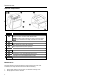
INTRODUCTION Scanner Components Figure 1. Scanner Components ITEM NO. n DESCRIPTION Utility Connector Located Under Rubber Seal The rubber seal protecting the utility connector should only be removed if the utility connector is to be used. o p q r s t u v 10-Pin RJ45, Female Socket Blue, White and Yellow LED Indicators Red Output Window (Laser Aperture) Pin Hole for Cable Release Speaker Three M2.5 x 0.45 Threaded Mounting Points Two M2.5 x 0.
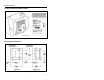
INTRODUCTION Caution and Serial Number Labels Figure 2. Mounting Specifications Figure 3.
INSTALLATION RS232, RS232 TTL or Light Pen 1. Turn off the host device. 2. Plug the male 10-pin RJ45 end of the PowerLink cable into the 10-pin socket on the IS3480. 3. Connect the 9-pin female end of the PowerLink cable to the host device. Note: Skip to step 6 if receiving power from the host device. 4. Plug the external power supply into the power jack on the PowerLink cable. Check the AC input requirements of the power supply to make sure the voltage matches the AC outlet.
INSTALLATION IBM 46xx or OCIA 1. Turn off the host device. 2. Plug the male 10-pin RJ45 end of the MVC cable into the 10-pin socket on the IS3480. 3. Connect the other end of the MVC cable to the host device. 4. Turn on the host device. Figure 5. When the scanner first receives power, the blue LED will turn on; the scanner will simultaneously beep once and flash the white LED. Plugging the scanner into the serial port of the PC does not guarantee that scanned information will appear at the PC.
INSTALLATION Keyboard Wedge 1. Turn off the host device. 2. Plug the male 10-pin RJ45 end of the PowerLink cable into the 10-pin socket on the IS3480. 3. Disconnect the keyboard from the host device. 4. Connect the “Y” end of the PowerLink cable to the keyboard and the keyboard port on the host PC. If necessary use the male/female adapter cable supplied with the scanner for proper connections. 5. Plug the external power supply into the power jack on the PowerLink cable.
INSTALLATION Stand-Alone Keyboard Wedge 1. Turn off the host device. 2. Plug the male 10-pin RJ45 end of the PowerLink cable into the 10-pin socket on the IS3480. 3. Connect the other end of the PowerLink cable to the keyboard port on the host device. 4. Plug the external power supply into the power jack on the PowerLink cable. Check the AC input requirements of the power supply to make sure the voltage matches the AC outlet. The outlet must be located near the equipment and be easily accessible. 5.
INSTALLATION Full Speed or Low Speed USB (Integrated) 1. Turn off the host device. 2. Plug the male 10-pin RJ45 end of the USB PowerLink cable into the 10-pin socket on the IS3480. 3. Plug the other end of the USB interface cable into the host device’s USB port. 4. Plug the external power supply in to the power jack on the USB PowerLink cable. Check the AC input requirements of the power supply to make sure the voltage matches the AC outlet.
INSTALLATION Notes for Low Speed USB (External with MX009) Metrologic’s MX009 USB cable is a device that converts serial RS232 formatted data to either USB Keyboard or USB Point-of-Sale communication protocol. Please refer to the MX009 USB Converter Cable Programming Guide (MLPN 00-02574) supplied with your MX009 cable for detailed installation and programming guidelines. Notes for Laser Emulation IS3480-00 Only The IS3480-00 leaves the factory with the Laser Emulation Mode enabled.
SCANNER OPERATION Configurable Primary and Secondary Scan Pattern Modes There are two configurable scan pattern modes available with the IS3480. • The primary scan pattern mode is the default scan pattern active when the scanner starts. • The secondary scan pattern mode is activated by pressing the button located on the side of the scanner. This mode is also referred to as the button mode.
SCANNER OPERATION Configurable Button Functions SECONDARY SCAN PATTERN BUTTON CLICK MODE WITH CODEGATE ENABLED For illustration purposes the unit’s primary scan pattern has been set to all scan lines (omnidirectional reading) and the secondary pattern has been set to single-line (menu reading) with a 10 second button click timeout configured. 1. The primary scan pattern is active when the scanner starts. 2. To activate the secondary scan pattern, press and release the button. 3.
SCANNER OPERATION Configurable Button Functions SECONDARY SCAN PATTERN BUTTON CLICK MODE WITH CODEGATE DISABLED For illustration purposes the unit’s primary scan pattern has been set to all scan lines (omnidirectional reading) and the secondary pattern has been set to single-line (menu reading) with a 10 second button click timeout configured. 14 1. The primary scan pattern is active when the scanner starts. 2. To activate the secondary scan pattern, press and release the button. 3.
SCANNER OPERATION Configurable Button Functions SECONDARY SCAN PATTERN BUTTON HOLD MODE WITH CODEGATE ENABLED For illustration purposes the unit’s primary scan pattern has been set to all scan lines (omnidirectional reading) and the secondary pattern has been set to single-line (menu reading) with a 10 second button click timeout configured. 1. The primary scan pattern is active when the scanner starts. 2. To activate the secondary scan pattern, press and hold the button. 3.
SCANNER OPERATION Configurable Button Functions SECONDARY SCAN PATTERN BUTTON HOLD MODE WITH CODEGATE DISABLED For illustration purposes the unit’s primary scan pattern has been set to all scan lines (omnidirectional reading) and the secondary pattern has been set to single-line (menu reading) with a 10 second button click timeout configured. 16 1. The primary scan pattern is active when the scanner starts. 2. To activate the secondary scan pattern, press and hold the button. 3.
SCANNER OPERATION Sweet Spot Mode The sweet spot mode is used to determine where the maximum read rate area or “sweet spot” is located for a specific bar code type. When activated this mode provides visual and audible feedback indicating how the scanner is scanning.
SCANNER OPERATION Audible Indicators When the IS3480 is in operation, it can provide audible feedback. These sounds indicate the status of the scanner. Eight settings are available for the tone of the beep (normal, 6 alternate tones and no tone). For instruction on how to change the tone of the beeper, refer to the MetroSelect Configuration Guide (00-02407).
SCANNER OPERATION Visual Indicators There are four LEDs located on the top of the IS3480. When the scanner is on, the flashing or constant illumination of the LEDs indicates the status of the current scan and the scanner. No LEDs The LEDs will not be illuminated if the scanner is not receiving power from the host or transformer. They are also not illuminated when all lasers are turned off for any reason. Steady Blue When the laser is active, the blue LED is illuminated.
SCANNER OPERATION Failure Mode Indicators Flashing Blue and One Razzberry Tone This indicates that the scanner has experienced a laser subsystem failure. Return the unit to an authorized service center for repair. Flashing Blue and White and Two Razzberry Tones This indicates that the scanner has experienced a motor failure. Return the unit to an authorized service center for repair.
SCANNER OPERATION Depth of Field Specifications* Normal Scan Zone Specifications are based on a 0.33 mm (13 mil) bar code. Figure 9. Normal Depth of Field * All specifications are subject to change without notice.
SCANNER OPERATION Depth of Field Specifications* Reduced Scan Zone Specifications are based on a 0.33 mm (13 mil) bar code. Figure 10. Reduced Depth of Field * All specifications are subject to change without notice.
SCANNER OPERATION Depth of Field by Bar Code Element Width* Normal Scan Zone MINIMUM BAR CODE ELEMENT W IDTH A B C D E F mm .13 .15 .19 .25 .33 .66 mils 5.2 5.7 7.5 10 13 26 Figure 11. Normal Scan Zone by Bar Code Element Width * All specifications are subject to change without notice.
SCANNER OPERATION Depth of Field by Bar Code Element Width* Reduced Scan Zone MINIMUM BAR CODE ELEMENT W IDTH A B C D E F mm .13 .15 .19 .25 .33 .66 mils 5.2 5.7 7.5 10 13 26 Figure 12. Reduced Scan Zone by Bar Code Element Width * All specifications are subject to change without notice.
SCANNER OPERATION IR Activation Range* Normal Figure 13. Normal IR Activation Range Reduced Figure 14. Reduced IR Activation Range * All specifications are subject to change without notice.
TROUBLESHOOTING GUIDE The following guide is for reference purposes only. Contact a Metrologic representative at 1-800-ID-METRO or 1-800-436-3876 to preserve the limited warranty terms on page 45. Symptoms Possible Cause(s) Solution All Interfaces The unit has no LEDs, beeper or motor spin. No power is being supplied to the scanner. Check the transformer, outlet and power strip. Make sure the cable is plugged into the scanner. The unit has no LEDs and / or beeper.
TROUBLESHOOTING GUIDE Symptoms Possible Cause(s) Solution The unit scans a bar code, but locks up after the first scan (the white LED stays on). The scanner is configured to support some form of host handshaking but is not receiving the signal. If the scanner is setup to support ACK/NAK, RTS/CTS, XON/XOFF or D/E, verify that the host cable and host are supporting the handshaking properly. The unit scans but the data transmitted to the host is incorrect.
TROUBLESHOOTING GUIDE Symptoms Possible Cause(s) Solution All Interfaces During power up the unit beeps 3 times. There is a non-volatile RAM failure. Contact a Metrologic service representative. During power up the unit razzes continuously. There is a RAM or ROM failure. Contact a Metrologic service representative. During power up the unit razzes once and the blue LED flashes. There is a VLD failure. Contact a Metrologic service representative.
TROUBLESHOOTING GUIDE Symptoms Possible Cause(s) Solution RS232 Only The host is The scanner and host receiving data may not be configured but the data does for the same interface. not look correct. Characters are being dropped. The intercharacter delay needs to be added to the transmitted output. Check that the scanner and the host are configured for the same interface. Add some intercharacter delay to the transmitted output by using the MetroSelect Configuration Guide (MLPN 00-02407).
DESIGN SPECIFICATIONS IS3480 Operational Light Source: Visible Laser Diode (VLD) @ 650 nm Laser Power: 1.1 mW Normal Depth of Field: Reduced Depth of Field: 25 mm - 280 mm (1”- 11”) 25 mm - 150 mm (1”- 6”) 0.33 mm (13 mil) bar code Omni Scan Scan Speed: No. of Scan Lines: 1650 scan lines per second 20 Single-Line Scan Speed: No. of Scan Lines: Motor Speed: Min Bar Width: 80 scan lines per second 1 5000 RPM 0.127 mm (5.
DESIGN SPECIFICATIONS IS3480 Electrical Voltage Supply: Operating Power: Standby Power: 5VDC ± 0.25V 1.375 W 1.0 W Operating Current: 275 mA typical at 5VDC Standby Current: 200 mA typical at 5VDC DC Transformers: Laser Class 1: EMC: Class II; 5.
APPLICATIONS AND PROTOCOLS The model number on each scanner includes the scanner number and factory default communications protocol.
DEFAULT SETTINGS - COMMUNICATION PARAMETERS Many functions of the scanner can be "programmed" - that is enabled or disabled. The scanner is shipped from the factory programmed to a set of default conditions. The default parameter of the scanner has an asterisk ( * ) in the charts on the following pages. If an asterisk is not in the default column then the default setting is Off or Disabled. Every interface does not support every parameter.
DEFAULT SETTINGS - COMMUNICATION PARAMETERS RS232* PARAMETER Expanded ID “]e0” DEFAULT * RSS Limited Enable OCIA USB OR RS232 TTL LIGHT IBM KBW PEN 46XX LASER EMULATION 9 9 9 9 9 9 9 9 9 9 9 9 9 9 RSS Limited ID “]e0” * 9 9 9 9 9 9 9 RSS Limited App ID “01” * 9 9 9 9 9 9 9 RSS Limited Check Digit * 9 9 9 9 9 9 9 Bars High as Code 39 * 9 9 Spaces High as Code 39 9 9 Bars High as Scanned 9 9 9 9 Spaces High as Scanned 9 DTS/SIEMENS DTS/NIXDORF *
DEFAULT SETTINGS - COMMUNICATION PARAMETERS RS232* PARAMETER Transmit UPC-A Check Digit DEFAULT * OCIA USB 9 Transmit UPC-E Check Digit OR RS232 TTL LIGHT IBM KBW PEN 46XX LASER EMULATION 9 9 9 9 9 9 9 9 9 9 9 9 9 9 9 9 9 9 9 9 9 9 Expand UPC-E 9 9 9 Convert UPC-A to EAN-13 9 9 9 Transmit Lead Zero on UPC-E 9 9 9 Convert EAN-8 to EAN-13 9 9 9 9 9 Transmit UPC-A Number System * 9 9 9 9 9 9 9 Transmit UPC-A Manufacturer ID# * 9 9 9 9 9 9 9 Tr
DEFAULT SETTINGS - COMMUNICATION PARAMETERS RS232* PARAMETER DEFAULT OCIA USB OR RS232 TTL LIGHT IBM LASER KBW PEN 46XX EMULATION Nixdorf ID 9 9 9 LRC Enabled 9 9 9 UPC Prefix 9 9 9 UPC Suffix 9 9 9 Transmit AIM ID Characters 9 9 9 STX Prefix 9 9 9 ETX Suffix 9 9 9 Carriage Return * 9 9 9 Line Feed - disabled by default in KBW * 9 9 9 Tab Prefix 9 9 9 Tab Suffix 9 9 9 “DE” Disable Command 9 “FL” Laser Enable Command 9 DTR Handshaking Support 9 RTS/CT
DEFAULT SETTINGS - COMMUNICATION PARAMETERS RS232* PARAMETER DEFAULT OCIA USB OR RS232 TTL LIGHT IBM PEN 46XX KBW LASER EMULATION Supplements are not Required * 9 9 9 9 9 9 9 Two Digit Redundancy * 9 9 9 9 9 9 9 9 9 9 9 9 9 9 9 9 9 9 9 9 9 9 9 9 as code 39 9 9 as code 39 9 9 9 9 9 9 9 Five Digit Redundancy 100 msec to Find Supplement Programmable in 100msec steps (MAX 800 msec) * Coupon Code 128 Programmable Code Lengths 7 avail.
UPGRADING THE FLASH ROM FIRMWARE The MetroSet2 program is a functional component of Metrologic’s new line of Flash- based scanners. This program allows the user of a Metrologic scanner to quickly upgrade to a new or custom version of firmware. It requires the use of a personal computer running Windows 95 or greater and the use of a serial port. The user merely connects the scanner to a serial port on the PC, launches the MetroSet2 program, and blasts off to new software upgrades.
SCANNER AND CABLE TERMINATIONS Scanner Pinout Connections The IS3480 scanner interfaces terminate to a 10-pin modular socket. The serial # label indicates the interface enabled when the scanner is shipped from the factory. Figure 15.
SCANNER AND CABLE TERMINATIONS IS3480-11 IBM 468X/469X Pin Function IS3480-9 OCIA Pin 1 2 3 4 5 6 7 Ground RS232 Transmit Output RS232 Receive Input RTS Output CTS Input DTR Input IBM B-Transmit 1 2 3 4 5 6 7 8 IBM A+ Receive 8 9 10 +5VDC Shield Ground 9 10 Function Ground RS232 Transmit Output RS232 Receive Input RDATA RDATA Return Clock In Clock Out Clock in Return/ Clock out Rtrn +5VDC Shield Ground IS3480-00 Laser Emulation Pin 1 2 3 4 5 6 7 8 9 10 Function Ground RS232 Transmit Output RS2
SCANNER AND CABLE TERMINATIONS Cable Connector Configurations (Host End) “Standard” PowerLink Cable 53-53xxx-3 coiled or 54-54xxx-3 straight Pin Function 1 Shield Ground 2 RS232 Transmit Output 3 RS232 Receive Input 4 DTR Input/Light Pen Source 5 Power/Signal Ground 6 Light Pen Data 7 CTS Input 8 RTS Output 9 +5VDC 9 5 6 1 9-Pin D-Type Connector USB Power/Communication Cable 54-54213x-N-3, 54-540214x-N-3 or 54-54235x-N-3 Pin Function 1 PC +5V/V_USB 2 D- 3 D+ 4 Ground USB T
SCANNER AND CABLE TERMINATIONS Cable Connector Configurations (Host End) Keyboard Wedge PowerLink Cable 54-54002x-3 Pin Function 1 Keyboard Clock 2 Keyboard Data 3 4 5 Pin 1 2 3 4 5 6 No Connect Power Ground +5 Volts DC Function PC Data No Connect Power Ground +5 Volts DC PC Clock No Connect 5-Pin DIN, Female 6-Pin DIN, Male Metrologic will supply an adapter cable with a 5-pin DIN male connector on one end and a 6-pin mini DIN female connector on the other.
LASER AND PRODUCT SAFETY Caution Use of controls or adjustments or performance of procedures other than those specified herein may result in hazardous laser light exposure. Under no circumstances should the customer attempt to service the laser scanner. Never attempt to look at the laser beam, even if the scanner appears to be nonfunctional. Never open the scanner in an attempt to look into the device. Doing so could result in hazardous laser light exposure.
LASER AND PRODUCT SAFETY Notices This equipment has been tested and found to comply with limits for a Class A digital device, pursuant to part 15 of the FCC Rules. These limits are designed to provide reasonable protection against harmful interference when the equipment is operated in a commercial environment. This equipment generates, uses and can radiate radio frequency energy and, if not installed and used in accordance with the instruction manual, may cause harmful interference to radio communications.
LIMITED W ARRANTY The IS3480 Quantum™E scanners are manufactured by Metrologic at its Blackwood, New Jersey, U.S.A. facility. The IS3480 QuantumE scanners have a three (3) year limited warranty from the date of manufacture. Metrologic warrants and represents that all IS3480 QuantumE scanners are free of all defects in material, workmanship and design, and have been produced and labeled in compliance with all applicable U.S.
PATENTS Patent Information This METROLOGIC product may be covered by one or more of the following U.S. Patents: U.S. Patent No.
INDEX A AC .......................................2, 6–10 Accessories ...............................2, 3 Adapter..........................................8 Audible Indicator.............12, 18–20, 26–29, 38 B Bar Code ............. 18–20, 26–29, 30 Bar Width.....................................30 Beep.............. 18, 19, 20, 26–29, 38 Blue LED ............. 18–20, 26–29, 38 Button................................4, 12–17 C Cable Communication...............2, 6–10, 26–29, 38, 41–42 Keyboard Wedge ......
INDEX Manual...............................2, 18, 32 Meteor .........................................38 MetroSet2....................................38 Mode of Operation Button ......................................17 Primary ..............................12–17 Secondary..........................12–17 Sweet Spot Mode ..............17, 37 Motor Speed................................30 Mounting Specifications ................5 MX009 .........................................11 S OCIA..........................
NOTES
August 2004 Printed in the USA 00 - 020 26C