
Laser Bar CodeTM Projection Scanner Installation and User's Guide TECH 8

9
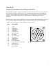
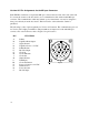
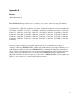
Figure 4
Appendix B
Version A1 Pin Assignments for the Mil spec Connector
Each TECH 8 scanner has a 19-pin male Mil spec connector that is found on the side of the unit.
To connect the scanner to the host device, use a communication cable with a female Mil spec
connector. The communication cable may include a power transformer or it may be designed to
draw power directly from the host device. This item can be ordered when the scanner is
purchased.
The following is a list of pin assignments for Version A1 scanners. The communication protocols
for Version A1 are RS-232 and OCIA. The pin numbers are impressed on the male Mil spec
connector. For easier reference, refer to Figure 4 for pin locations.
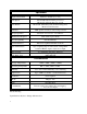
PIN FUNCTION
A R Data
B RTS Output
C Signal Ground
D CTS Input
E R Data Return
F RS-232 Output
G Clock In
H Clock In Return
J Clock Out
K Shield Ground
L DTR Input
M Clock Out Return
N Power to Scanner + 24 VDC
P Earth Ground
R Power Ground
S RS-232 Input