METROLOGIC INSTRUMENTS, INC.
LOCATIONS Corporate Headquarters North America Metrologic Instruments, Inc. 90 Coles Road Blackwood, NJ 08012-4683 Customer Service: 1-800-ID-METRO Tel: 856-228-8100 Fax: 856-228-6673 Email: info@metrologic.com Internet: www.metrologic.com European Headquarters Germany, Middle East and Africa Metrologic Instruments GmbH Dornierstrasse 2 82178 Puchheim b. Munich, Germany Tel: +49 89 89019 0 Fax: +49 89 89019 200 Email: info@europe.metrologic.com Germany Email: info@de.metrologic.
TABLE OF CONTENTS Introduction........................................................................................................... 1 Accessories and Supplies .................................................................................... 2 Quick Start............................................................................................................ 3 Standard Scanner Installation ..............................................................................
INTRODUCTION The MS6220 Pulsar® is an entry-level hand held contact laser bar code scanner that combines the high-speed and accuracy of a laser scanner with the working range and price of a typical CCD. Pulsar has a controlled 7.6 cm (3”) depth of field on 100% UPC bar codes, which makes it perfect for large retail applications where UPC/EAN bar codes are frequently scanned at less demanding, low-volume check-out areas or satellite cash registers.
ACCESSORIES AND SUPPLIES The following is a list of parts that may or may not be included in a MS6220 kit. • ® MS6220 Pulsar Single-Line Contact Laser Scanner • AC to DC Power Transformer – Regulated 5.2VDC @ 650 mA output • • One of the following may be included: • 120 V United States [ MLPN 45-45593 ] • 220 V - 240 V Continental European [ MLPN 45-45591 ] • 220 V – 240 V United Kingdom [ MLPN 45-45592 ] PowerLink Cable with built in power jack.
QUICK START 1. Connect the 10-pin RJ45 male connector into the jack on the Pulsar® MS6220. You will hear a ‘click’ when the connection is made. 2. Connect the L-shaped plug of the power supply into the power jack on the PowerLink cable. 3. Connect the power supply into an AC outlet. Make sure the AC input requirements of the power supply match the AC outlet. (See caution statement below) p n 4.
STANDARD SCANNER INSTALLATION 1. Turn off the host system. 2. Connect the 10-pin RJ45 male connector of the PowerLink cable into the jack on the MS6220. Note: If the MS6220 is receiving power from the host system, skip to step #5. (See caution statement below*) 3. Connect the L-shaped plug of the power supply into the power jack on the PowerLink cable. (See caution statement below**) 4. Make sure the AC input requirements of the power supply match the AC outlet.
KEYBOARD WEDGE INSTALLATION 1. Turn off the host system. 2. Connect the 10-pin RJ45 male connector of the PowerLink cable into the jack on the MS6220. 3. Connect the L-shaped plug of the power supply into the power jack on the PowerLink cable (refer to the manufacturer’s recommendation on page 6). 4. Make sure the AC input requirements of the power supply match the AC outlet. Connect the power supply into an AC outlet (see caution statement below**). 5. Disconnect the keyboard from the host system.
KEYBOARD WEDGE INSTALLATION (CONTINUED) Manufacturer’s Recommendation If the keyboard port of the host system cannot supply enough current, the use of an external power supply with the MS6220 Keyboard Wedge will be necessary. Powering the MS6220 directly from the computer keyboard connector could interfere with the operation of the scanner or the computer.
DISCONNECTING THE POWERLINK CABLE FROM THE SCANNER Before removing the cable from the scanner, Metrologic recommends that the power on the host system is off and the power supply has been disconnected from the PowerLink cable. o& p q n 1. Locate the small ‘pin-hole’ on the back of the scanner. 2. Bend an ordinary paperclip into the shape shown above. 3. Insert the paperclip (or other small metallic pin) into the small ‘pin-hole’. 4. You will here a faint ‘click’.
SCANNER PARTS 1. Green & Red LEDs The MS6220 laser pulses on and off during normal operation. The green LED remains on during normal pulse operation and it blinks during power save mode. On a successful read of a bar code, the red LED will flash and the scanner will beep once. The LEDs are also used as diagnostic indicators and mode indicators. 2. Output Window Laser Light emits from this aperture. 3.
AUDIBLE INDICATORS When the MS6220 scanner is operational, it provides audible feedback. These sounds indicate the status of the scanner. Eight settings are available for the tone of the beep (normal, 6 alternate tones and no tone). To change the tone, refer to the Configuration Guide. One Beep – on power up The green LED will turn on, then the red LED will flash and the scanner will beep once. The red LED will remain on for the duration of the beep. The scanner is now ready to scan.
VISUAL INDICATORS There is a red LED and a green LED on the MS6220. When the scanner is on, the activity of the LEDs indicates the status of the current scan and the scanner. Green and Red LEDs are off The LEDs will not be illuminated if the scanner is not receiving power from the host or transformer. Steady Green Indicates normal pulse or continuous laser operation. Accompanied by a razzberry tone, it indicates that an invalid bar code has been scanned.
FAILURE MODES One Razzberry Tone on Power-up This indicates the scanner has experienced a laser or flipper subsystem failure. Return the unit for repair to a Metrologic Authorized Service Center. Continuous Razzberry Tone with all LEDs off If, upon power up, the scanner emits a continuous razzberry tone, then the scanner has an experienced an electronic failure. Return the unit for repair to a Metrologic Authorized Service Center.
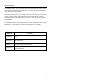
SCAN AREA Minimum Bar Code Element Width 12 A B C D E F mm .10 .12 .17 .26 .33 .66 mils 4.1 4.8 6.8 10.
LABELS Each scanner has two labels on the underside of the unit. The first label has the model number, date of manufacture, and caution information. The second label shows the serial number and the laser information. The following are examples of these labels: MAINTENANCE Smudges and dirt on the window of a bar code scanner can interfere with proper scanning. Therefore, the output window will need occasional cleaning. 1. Spray glass cleaner onto a lint-free, non-abrasive cleaning cloth. 2.
TROUBLESHOOTING GUIDE The following guide is for reference purposes only. Contact a Metrologic representative at 1-800-ID-METRO or 1-800-436-3876 to preserve the limited warranty terms on page 28. SYMPTOMS POSSIBLE CAUSE(S) SOLUTION No power is being supplied to the scanner Check transformer, outlet and power strip. Make sure the cable is plugged into the scanner. No power is being supplied to the scanner from host Some host systems cannot supply enough current to power the MS6220.
TROUBLESHOOTING GUIDE (CONTINUED) SYMPTOMS POSSIBLE CAUSE(S) SOLUTION The unit powers up, but does not scan Scanning a particular symbology that is not enabled UPC/EAN, Code 39, Interleaved 2 of 5, Code 93, Code 128 and Codabar are enabled by default. Verify that the type of bar code being read has been selected.
TROUBLESHOOTING GUIDE (CONTINUED) SYMPTOMS POSSIBLE CAUSE(S) SOLUTION Scanner beeps at some bar codes and NOT for others of the same bar code symbology The bar code may have been printed incorrectly Check if it is a check digit/character/or border problem. Scanner beeps at some bar codes and NOT for others of the same bar code symbology The scanner is not configured correctly for this type of bar code Check if check digits are set properly.
TROUBLESHOOTING GUIDE (CONTINUED) SYMPTOMS The unit is not transmitting each character (Keyboard Wedge) POSSIBLE CAUSE(S) SOLUTION Configuration is not correct Increase interscan code delay setting. Adjust whether the F0 break is transmitted. It may be necessary to try this in both settings. Alpha characters show as lower case (Keyboard Wedge) Computer is in Caps Lock mode Enable Caps Lock detect setting of the scanner to detect whether the PC is operating in Caps Lock.
RS-232 DEMONSTRATION PROGRAM If an RS-232 scanner is not communicating with your IBM compatible PC, key in the following BASIC program to test that the communication port and scanner are working. This program is for demonstration purposes only. It is only intended to prove that cabling is correct, the communication port is working, and the scanner is working. If the bar code data displays on the screen while using this program, it only demonstrates that the hardware interface and scanner are working.
APPENDIX A Specifications OPERATIONAL Light Source Visible Laser Diode 650 nm ± 10 nm or 675 nm ± 5 nm Laser Power 0.75 mW (peak) Depth of Scan Field 0 mm – 64 mm (0” – 2.5”) for 0.33 mm (13 mil) bar code at default setting Scan Speed 72 ± 2 scan lines per second Scan Pattern Single scan line Minimum Bar Width 0.102 mm (4.
APPENDIX A (CONTINUED) ELECTRICAL Input Voltage 5 VDC ± 0.25 V Power - Operating 800 mW Current - Operating 160 mA peak @ 5 VDC DC Transformers Class 2; 5.2 V @ 650 mA UL UL listed for US and Canada; UL 1950, C22.2 No.
APPENDIX B Default Settings Many functions of the scanner can be “programmed” – that is, enabled or disabled. The scanner is shipped from the factory programmed to a set of default conditions. The default parameter of the scanner has an asterisk (*) in the charts on the following pages. If an asterisk is not in the default column then the default setting is OFF or DISABLED. Every communication does not support every parameter.
APPENDIX B (CONTINUED) Parameter Default OCIA RS-232 Light Pen IBM 46XX KBW ITF Symbol Lengths Variable 9 9 9 9 9 3 9 9 9 9 9 None 9 9 9 9 9 9 9 9 9 9 9 9 9 9 9 9 9 9 9 9 9 9 9 9 9 9 9 9 9 9 9 9 9 9 9 9 9 9 9 9 9 9 9 9 9 9 9 9 9 9 9 9 9 9 9 9 9 9 9 9 9 9 9 9 9 9 9 9 9 9 9 9 9 9 9 9 9 9 Minimum Symbol Length Symbol Length Lock Bars High as Code 39 Spaces High as Code 39 Bars High as Scanned Spaces High as Scanned Low Speed Option Togg
APPENDIX B (CONTINUED) Parameter Expand UPC-E Convert UPC-A to EAN-13 Transmit lead zero on UPC-E Transmit UPC-A number system Transmit UPC-A Manufacturer ID# Transmit UPC-A Item ID# Transmit Codabar Start/Stop Characters CLSI Editing (Enable) Transmit Mod 10/ITF Transmit MSI-Plessy Parity Baud Rate 8 Data Bits 7 Data Bits Stop Bits Manufacturer’s ID Scanner ID Transmit Sanyo ID Characters Nixdorf ID Aim ID Sineko ID Sni Beetle ID Tec ID NCR ID Rochford Thomson ID Family Dollar ID LRC Enabled UPC Prefix UPC
APPENDIX B (CONTINUED) Parameter OCIA RS-232 9 9 9 9 9 9 9 9 9 9 9 Five Digit Supplements 9 9 Bookland (978) 977 (2 digit) Supplemental Requirement Supplements are not Required Two Digit Redundancy Five Digit Redundancy Number System 5 Supplements FR.
APPENDIX C Scanner Pinout Connections The MS6220 scanner interfaces terminate to a 10-pin modular jack. The serial # label indicates the interface enabled when the scanner is shipped from the factory.
APPENDIX C (CONTINUED) MS6220-47 Keyboard Wedge 1 10 Pin 1 2 3 4 5 6 7 8 9 10 Function Ground RS-232 Transmit Output RS-232 Receive Input PC Data PC Clock KB Clock PC +5V KB Data +5VDC Shield Ground Cable Connector Configurations “Standard” PowerLink cable (MLPN 53000 or 54000) 9-pin D-type female connector to the PC Pin 1 2 3 4 5 6 7 8 9 6 1 9 5 Function Shield Ground RS-232 Transmit Output RS-232 Receive Input DTR Input Power/Signal Ground Light Pen Data CTS Input RTS Output +5VDC* 9-Pin D-Type
APPENDIX C (CONTINUED) Keyboard Wedge PowerLink and Adapter Cable The Keyboard Wedge PowerLink cable is terminated with a 5-pin DIN female connector on one end, and a 6-pin mini DIN male on the other. 4 2 5 1 1 2 3 4 3 6 5 Keyboard Wedge PowerLink Cable 5-Pin DIN, Female 6-Pin DIN, Male Metrologic will supply an adapter cable with a 5-pin DIN male connector on one end and a 6-pin mini DIN female connector on the other.
APPENDIX D Warranty and Disclaimer Limited Warranty The MS6220 scanners are manufactured by Metrologic at its Blackwood, New Jersey, U.S.A. facility. The MS6220 scanners have a two (2) year limited warranty from the date of manufacture. Metrologic warrants and represents that all MS6220 scanners are free of all defects in material, workmanship and design, and have been produced and labeled in compliance with all applicable U.S.
APPENDIX E Notices Notice This equipment has been tested and found to comply with limits for a Class A digital device, pursuant to Part 15 of the FCC Rules. These limits are designed to provide reasonable protection against harmful interference when the equipment is operated in a commercial environment. This equipment generates, uses and can radiate radio frequency energy and, if not installed and used in accordance with the instruction manual, may cause harmful interference to radio communications.
APPENDIX E (CONTINUED) Achtung Die Verwendung anderer als der hier beschriebenen Steuerungen, Einstellungen oder Verfahren kann eine gefährliche Laserstrahlung hervorrufen. Der Kunde sollte unter keinen Umständen versuchen, den Laser-Scanner selbst zu warten. Sehen Sie niemals in den Laserstrahl, selbst wenn Sie glauben, daß der Scanner nicht aktiv ist. Öffnen Sie niemals den Scanner, um in das Gerät hineinzusehen. Wenn Sie dies tun, können Sie sich einer gefährlichen Laserstrahlung aussetzen.
APPENDIX F Patent Information “This METROLOGIC product may be covered by one or more of the following U.S. Patents: U.S. Patent No.; 4,958,894; 5,484,992; 5,661,292; 5,925,870; 5,081,342; 5,525,789; 5,777,315; 6,029,894; 5,216,232; 5,528,024; 5,789,730; 6,209,894; 5,260,553; 5,340,971; 5.
INDEX A F AC input/outlet...................2, 3, 4, 6 Accessories ...................................2 Approvals ........................ 13, 20, 30 Assignments pin ...................... 2, 4, 6, 7, 26, 27 Audible ..............................9, 11, 19 Autodiscriminates ........................19 Failure indicator(s) ............ 9, 11, 14 Failure modes ............................. 11 B Bar code ...1, 3, 8-10, 15, 16, 18, 19 Bar width .....................................12 Beep ......
INDEX P Specifications.............................. 19 Parts ..........................................2, 8 Power supply............... 3, 4, 6, 7, 26 Programming modes ......... 3, 17, 18 T Q Quick start .....................................3 R Razzberry tone ............ 9, 10, 11, 22 Red LED.................. 3, 4, 6, 8, 9, 10 Repair....................................11, 28 RMA ............................................28 RS-232 ............ 1, 17, 18, 19, 21, 26 S Tones .....................
NOTES
June 2002 0 0 - 0 2 4 4 7