METROLOGIC INSTRUMENTS, INC.
Copyright © 2005 by Metrologic Instruments, Inc. All rights reserved. No part of this work may be reproduced, transmitted, or stored in any form or by any means without prior written consent, except by reviewer, who may quote brief passages in a review, or provided for in the Copyright Act of 1976. Products and brand names mentioned in this document are trademarks of their respective companies.
TABLE OF CONTENTS Introduction Models and Accessories ...................................................................................... 1 Components of the microQuest........................................................................ 2 Labels............................................................................................................... 2 Mounting Specifications Scan Engine Dimensions .................................................................................
TABLE OF CONTENTS Canada........................................................................................................... 21 Cautions ......................................................................................................... 22 Limited Warranty ................................................................................................ 23 Patents ............................................................................................................... 24 Index .............
INTRODUCTION The IS4800 microQuest® series are miniature single-line scan engines designed for direct integration into customer decode-equipped OEM devices. The microQuest non-decode scan engine is equipped with a multitude of features including: • • • • • • • • • 100 Scans per Second, Typical. Support for 3.3VDC Input Voltage (IS4813 Model) Support for 5VDC Input Voltage (IS4815 Model) A 650 nm Bright Laser Diode A narrow exit angle to provide precision beam positioning.
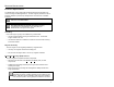
COMPONENTS OF THE MICROQUEST Figure 1. IS4800 Series Components ITEM NO. DESCRIPTION Pin Locator Holes (specifications on page 3) Threaded Mounting Points (specifications on page 3) Exit Beam Location, Laser Light Aperture AVOID EXPOSURE – LASER LIGHT IS EMITTED FROM THIS APERTURE Die Cast Chassis 10-Pin ZIF Connector Printed Circuit Board LABELS The serial number/model number label is located on engine chassis (see below). Figure 2.
MOUNTING SPECIFICATIONS Scan Engine Dimensions Figure 3. IS4800 Series Dimensions Specifications are subject to change without notice.
MOUNTING SPECIFICATIONS Exit Beam Specifications Figure 4. IS4800 Series Exit Beam Specifications Specifications are subject to change without notice.
MOUNTING SPECIFICATIONS Enclosure Specifications The IS4800 scan engine series was specifically designed for integration into custom housings for OEM applications. The scan engine’s performance will be adversely affected or permanently damaged when mounted in an unsuitable enclosure. THIS DEVICE DOES NOT COMPLY WITH 21 CFR 1040. USE ONLY AS COMPONENT. The limited warranty (on page 23) is void if the following considerations are not adhered to when integrating the IS4800 series scan engine into a system.
MOUNTING SPECIFICATIONS Enclosure Specifications Printed Circuit Board (PCB) Component Clearance WARNING: When designing the IS4800 into the final product, be sure to eliminate all possible means of shorting Resistors R3 and R25 in the IS4800. A short could enable the scan engine to emit Class 3R radiation. Any CDRH filing will require a disclosure of the design ensuring a method to mitigate a potential short. Figure 5.
MOUNTING SPECIFICATIONS Enclosure Specifications Output Window Properties Please contact a Metrologic representative to coordinate the best window material required to maintain laser safety requirements for your application. An improperly placed window has the potential to seriously reduce the scan engine’s performance. Careful consideration must be made when designing the output window’s distance and angle placement relative to the scan engine’s exit beam and chassis.
MOUNTING SPECIFICATIONS Enclosure Specifications Output Window Coatings • Anti-Reflection An anti-reflective coating can be applied to the inside and/or outside of the window to reduce the possibility of internal beam reflections interfering with the scan performance of the engine. If an anti-reflective coating is applied it is recommended that it be on both sides of the window providing a 0.5% maximum reflectivity on each side from 640 to 690 namometers at the nominal window tilt angle.
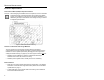
MOUNTING SPECIFICATIONS Enclosure Specifications Minimum Allowable Window Position Required To Avoid Detrimental Internal Reflective Beam Interference at Positive Exit Beam Angle Tolerance Figure 6. Minimum Projected Distance from the Engine’s Base to the Window’s Internal Surface (L) Minimum Window Angle θ +2.5° 5.0 28.0° +2.5° 10.0 14.5° +2.5° 15.0 10.5° +2.5° 20.0 8.0° +2.5° 25.0 7.0° +2.5° 30.0 6.5° +2.5° 35.0 6.0° +2.5° 40.0 5.5° +2.5° 45.0 5.0° +2.5° 50.0 5.
MOUNTING SPECIFICATIONS Enclosure Specifications Minimum Allowable Window Position Required To Avoid Detrimental Internal Reflective Beam Interference at Negative Exit Beam Angle Tolerance Figure 7. Exit Beam Depression Angle β Minimum Projected Distance from the Engine’s Base to the Window’s Internal Surface (M) Minimum Window Angle θ -2.5° 5.0 23.5° -2.5° 10.0 16.5° -2.5° 15.0 12.5° -2.5° 20.0 10.5° -2.5° 25.0 9.0° -2.5° 30.0 8.0° -2.5° 35.0 7.5° -2.5° 40.0 7.0° -2.5° 45.
DEPTH OF FIELD VS MINIMUM BAR CODE ELEMENT Figure 8. Depth of Field vs Minimum Bar Code Element MINIMUM BAR CODE ELEMENT WIDTH A B C D E mm .13 .19 .26 .33 .49 mils 5.2 7.5 10.4 13 19.5 For additional information please refer to the Barcode Element Time Calculation on page 17.
DESIGN SPECIFICATIONS IS4800 Series Engine Operational Light Source: Visible Laser Diode (VLD) @ 650 nm Laser Power: 1 mW Depth of Scan Field: 50 mm – 254 mm (2" – 10") for 0.33 mm (13 mil) bar codes Width of Scan Field: 74 mm (2.9") @ 50 mm (2.0"); 290 mm (11.4") @ 254 mm (10.0") Scan Speed: Scan Pattern: Minimum Bar Width: Print Contrast: Number Characters Read: Roll, Pitch, Yaw 100 Scan Lines per Second Typical Single Scan Line 0.127 mm (5.
DESIGN SPECIFICATIONS IS4800 Engine Series Electrical Input Voltage: IS4813 Engine 3.3VDC ± 10% IS4815 Engine 5.0VDC ± 5% IS4813 Engine 412.5 mW Power Consumption: Operating Current: Standby Current: IS4815 Engine 500 mW IS4813 Engine < 125 mA @ 3.3VDC IS4815 Engine < 100 mA @ 5.0VDC IS4813 Engine < 20 mA @ 3.3VDC IS4815 Engine < 10 mA @ 5.
SCAN ENGINE TERMINATIONS IS4813 Pinout Connections IS4813 10-Pin ZIF Figure 9. 10-Pin ZIF Pin Signal Name Function 1 No Connect No Connect 2 Power 3.
SCAN ENGINE TERMINATIONS IS4815 Pinout Connections IS4815 10-Pin ZIF Figure 10. 10-Pin ZIF Pin Signal Name Function 1 No Connect 2 Power 3 No Connect 4 Laser Enable* 5 Scan Enable* 6 Digitized Bar Pattern 7 Start of Scan 8 Ground Power Ground 9 Ground Power Ground 10 No Connect No Connect 5.
SCAN SENSE TIMING Timing Diagram The Timing Diagram (see Figure below) illustrates the correct power up procedure to ensure that the laser diode is not damaged upon start up of the unit. Upon start up, both scan Enable and Laser Enable are to be held high. In this state, both the scan mirror and the laser diode are not functional. A minimum of 2ms after the unit has obtained the proper working voltage; Scan Enable can be driven low to turn on the scan mirror.
SCAN SENSE TIMING Barcode Element Time Calculation Realization of the full depth of field for all barcodes given in the specification is based on the ability of the decoding hardware to resolve a varying range of minimum element times. The minimum element time calculation for a given barcode size at a given distance is shown in Equation 1(below). Minimum Element Time = (Element Size / Spot Speed) Equation 1. Example: Barcode Size = 5.
LASER AND PRODUCT SAFETY Regulatory Requirements THIS DEVICE DOES NOT COMPLY WITH 21 CFR 1040. USE ONLY AS COMPONENT. The IS4800 Series microQuest Laser Scan engines are designed to meet the requirements of IEC Class 2 in accordance with IEC 60825-1:1993+A1:1997+A2:2001. IEC Class 2 is defined as follows: Emission Duration: Accessible Emission Limit: Greater than 0.25 seconds Less than 0.001 W (1.
LASER AND PRODUCT SAFETY Europe The CE Mark is required on products which incorporate the IS4813 and the IS4815 scan engines if the products are to be imported into European Economic Area (EEA) countries. Use of the CE Mark requires compliance with directives and standards dependent upon the type of product. Information may be found at http://europa.eu.int/comm/enterprise/newapproach/.
LASER AND PRODUCT SAFETY United States Laser Safety To assist with the FDA filing requirements (refer to Regulatory Requirements), Metrologic has registered the scan engine with the FDA as a component. Customers can contact CDRH at the following address: Food and Drug Administration Center for Devices and Radiological Health Light Products Branch (HFX-312) Office of Compliance 2098 Gaither Road Rockville, MD 20850 Tel: 301-594-4654 www.fda.
LASER AND PRODUCT SAFETY Canada Laser Safety The Radiation Protection Bureau currently accepts products meeting the FDA standards in Canada. For more information contact: Radiation Protection Bureau 775 Brookfield Road Ottawa, Ontario K1A 1C1 EMC Products meeting FCC 47 CFR Part 15 will meet Industry Canada interference-causing equipment standard for digital apparatus, ICES-003. Additional testing is not required. A written notice indicating compliance must accompany the apparatus to the end user.
LASER AND PRODUCT SAFETY Cautions Caution Use of controls or adjustments or performance of procedures other than those specified herein may result in hazardous laser light exposure. Under no circumstances should the customer attempt to service the laser scanner. Never attempt to look at the laser beam, even if the scanner appears to be nonfunctional. Never open the scanner in an attempt to look into the device. Doing so could result in hazardous laser light exposure.
LIMITED WARRANTY The IS4800 microQuest® series scan engines are manufactured by Metrologic at its Blackwood, New Jersey, USA facility and its Suzhou, China facility. The microQuest scan engines have a two (2) year limited warranty from the date of manufacture.
PATENTS Worldwide patents pending.
INDEX A F Accessories ...................................1 Aperture.........................................2 Assignments pin .................................. 2, 14, 15 Faulty equipment ........................ 23 FDA....................................... 20, 21 B Ground .............................. 5, 14, 15 Beam aperture .....................................4 clearance ...................................5 exit angle ...........................1, 4, 8 exit location...............................
INDEX R U Regulatory Requirements.....18, 19, 20, 21 Canada Laser Safety ...............21 Europe Laser Safety ................19 United States Laser Safety ......20 Repair..........................................23 RMA ............................................23 UL ............................................... 13 S Scan enable ................................14, 15 Scan Field depth........................................12 width ........................................12 Scan Sense Timing .......
27
November 2005 Printed in USA 00 - 02019B