METROLOGIC INSTRUMENTS, INC.
Copyright © 2007 by Metrologic Instruments, Inc. All rights reserved. No part of this work may be reproduced, transmitted, or stored in any form or by any means without prior written consent, except by reviewer, who may quote brief passages in a review, or provided for in the Copyright Act of 1976. Trademarks Metrologic is a registered trademark of Metrologic Instruments, Inc. Products identified in this document are hereby acknowledged as trademarks, registered or otherwise, of Metrologic Instruments, Inc.
TABLE OF CONTENTS Introduction Product Overview ............................................................................................. 1 Models and Accessories................................................................................... 2 Components of the IS4920 Series Assembly (Non-Bracketed) ........................ 3 Components of the IS4920 Series Assembly (Bracketed)................................ 4 Components of the IS4910 (Imaging Engine)................................................
TABLE OF CONTENTS Usage of Host Interface Signals ..................................................................... 22 Descriptions of IS4920 Power Modes ............................................................ 25 Operational Timing Power Up/Boot Up.......................................................................................... 29 Power Down/Suspend/Power Removed ........................................................ 30 Decode Timing ......................................................
INTRODUCTION Product Overview IS4920 is a miniature area imaging decode engine with image capturing and bar code decoding capabilities. The imaging engine contains an area imaging engine (IS4910) and a decode board. The imaging engine features a mega-pixel CMOS sensor, integrated illumination and patented FirstFlash™ technology; together they ensure capturing a high-resolution image with optimal brightness each time.
INTRODUCTION Models and Accessories Part Number Designation † - Imaging Engine Types: Model IS4910 2 Mounting Option Description -00 • two blind holes for self-tapping screws -01 • • two blind holes for self-tapping screws two through holes located on tabs that extend from two sides of the engine's chassis -02 • • two blind holes for self-tapping screws threaded inserts located on tabs that extend from two sides of the engine's chassis
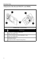
INTRODUCTION Components of the IS4920 Series (Non-Bracketed) Figure 1. IS4920 Components (Non-Bracketed Version) ITEM NO.
INTRODUCTION Components of the IS4920 Series (Bracketed) Figure 2. IS4920 Components (Bracketed Version) ITEM NO.
INTRODUCTION Components of the IS4910 (Imaging Engine) IS4910-00 ITEM NO. IS4910-01 / IS4910-02 DESCRIPTION 1 Targeting 2 Area Illumination 3 Camera Imager 4 FirstFlash Light Pipe 5 Mounting Points (see pages 10 - 11) 6 Mounting Points Provided for Self-Tapping Screw (see pages 9 - 11) 7 Keying Location (see pages 9 - 11) 8 Printed Circuit Boards 9 22-Pin, 0.50 mm (.020") Pitch SlimStack™ Plug, Molex P/N 55560-0227 Figure 3.
INTRODUCTION Components of the Decode PCB (TTL Level RS232) DECODE PCB (TTL LEVEL RS232) ITEM NO. 6 DESCRIPTION 1 12 POS FFC Connector .5MM Pitch, Molex P/N: 52559-1252 2 22-Pin, 0.50 mm (.020") Pitch SlimStack™ Plug, Molex P/N: 55560-0227 3 Mounting Points(s) Clearance for M2.
INTRODUCTION Components of the Decode PCB (USB) DECODE PCB (USB VERSION SHOWN) ITEM NO. DESCRIPTION 1 22-Pin, 0.50 mm (.020") Pitch SlimStack™ Plug, Molex P/N: 55560-0227 2 12 POS FFC Connector .5MM Pitch, Molex P/N: 52559-1252 3 Mounting Points(s) Clearance for M2.
INTRODUCTION Labels The serial number/model number label is located on the side of the engine. Figure 4. Imaging Module Serial Number Label Sample Figure 5.
MOUNTING SPECIFICATIONS IS4910-00 Dimensions The IS4910-00 model has two blind holes located on the bottom of the engine. These bind holes are provided for applications that require mounting with self-tapping screws. A keying location point is also provided on the bottom of the engine to assist with alignment. When securing the engine with self-tapping screws, Metrologic recommends: • using M2.2 x 4.5 Philips Pan Head, Type AB, Steel, Zinc Clear, Trivalent self-tapping screws • not exceeding 1.75 +0.
MOUNTING SPECIFICATIONS IS4910-01 Dimensions The IS4910-01 model has two blind holes located on the bottom of the engine for use with self-tapping screws. This model includes two additional clearance holes located on tabs extended from the sides of the engine's chassis. A keying location point is provided on the bottom of the engine to assist with alignment. When securing the engine with self-tapping screws, Metrologic recommends: • using M2.2 x 4.
MOUNTING SPECIFICATIONS IS4910-02 Dimensions The IS4910-02 model has two blind holes located on the bottom of the engine for use with self-tapping screws. This model includes two additional threaded inserts located on tabs extended from the sides of the engine's chassis. A keying location point is provided on the bottom of the engine to assist with alignment. When securing the engine with self-tapping screws, Metrologic recommends: • using M2.2 x 4.
MOUNTING SPECIFICATIONS Decode Board Dimensions (TTL Level RS232) Figure 9. Decode Board (TTL Level RS232) Dimensions Specifications are subject to change without notice.
MOUNTING SPECIFICATIONS USB Decode Board Dimensions Figure 10. Decode Board (USB) Dimensions Specifications are subject to change without notice.
MOUNTING SPECIFICATIONS Bracketed Module Dimensions Figure 11. IS4920 Bracketed Module Dimensions Specifications are subject to change without notice.
MOUNTING SPECIFICATIONS Enclosure Specifications The IS4920 imaging engine series was specifically designed for integration into custom housings for OEM applications. The imaging engine’s performance will be adversely affected or permanently damaged when mounted in an unsuitable enclosure. The limited warranty (on page 53) is void if the following considerations are not adhered to when integrating the IS4920 series area-imaging engine into a system.
MOUNTING SPECIFICATIONS Output Window Properties An improperly placed window has the serious potential to reduce the imaging engine’s performance. Careful consideration must be made when designing the output window’s distance and angle relative to the imaging engine’s camera aperture. Follow these guidelines when designing the output window. • The output window material should have a spectral transmission of at least 85% from 580 nm to 680 nm and should block shorter wavelengths.
MOUNTING SPECIFICATIONS Optical Clearance Specifications The window size and enclosure design must provide unobstructed clearance for the illumination and targeting areas shown below to avoid optical interference that decreases the engine's performance. Figure 12. IS4900 Series Optical Clearance Specifications Specifications are subject to change without notice.
ELECTRICAL CONSIDERATIONS In order to ensure proper operation of the IS4920’s electrical system, care must be taken to ensure the following requirements are met. Power Supply * The IS4920 is powered from the host device via the VIN and GND pins of the ZIF connector on the decode board. This voltage must be maintained within the specified voltage range (see electrical specs) at the decode board. Thus, voltage drops in the flex cable must be taken into account.
ELECTRICAL CONSIDERATIONS Thermal Considerations The IS4920 is qualified over the specified operational temperatures (0°C to 40°C) for all operating modes. Care must be taken to ensure that ambient temperatures do not exceed this range in order to guarantee operation. Operating the IS4920 in continuous mode for an extended period may produce considerable heating. This mode should be limited and sufficient airflow should be provided whenever possible to minimize internal heating.
THEORY OF OPERATION General Overview The IS4920 is a small area imaging barcode scanning engine designed for integration into handheld portable data terminals or other OEM devices specifically for the barcode scanning and/or OCR applications. The IS4920 functions like a digital camera and increases functionality and value to an OEM product by adding additional capabilities such as digital image capture, decoding of all standard 1D & 2D barcodes, reading OCR fonts, document lift, signature capture, etc.
THEORY OF OPERATION The host interface signals are described in the table below. Pin # IS4920-xx103 (TTL RS232) IS4920-xx38 (USB) 1 232INV NC 2 Vin Vin 3 GND GND 4 (n)RxD D- 5 (n)TxD 6 (n)CTS D+ 7 (n)RTS 8 PWRDWN PWRDWN Description Input: TTL RS232 polarity control with 68k ohm pull-up. Connect to ground for UART to UART signal polarity. Pull up to Vin or leave unconnected for standard TTL RS232 polarity. Power: Supply voltage input (3V to 5.
THEORY OF OPERATION Since many host systems and applications have unique formats and protocol requirements, the IS4920, just like all other Metrologic scanners, supports a wide range of configurable features that may be selected by scanning a corresponding scanner-programming barcode from MetroSelect Single Line Configuration Guide and Area Imaging Barcode Supplemental Configuration Guide, both available for download from the Metrologic web-site www.metrologic.com.
THEORY OF OPERATION The nTrig signal not only wakes the scanner up, but also immediately activates and turns the scanner into the Operating Mode. Either nWake or nTrig signals can be used to restart the IS4920-xx103 scanning engine when the engine is in Power-down Mode, which is indicated by the asserted (high) PWRDWN signal. The PWDWN pin is used to indicate when the IS4920 is in various operating modes such as Power Down, Suspend, and Boot.
THEORY OF OPERATION Figure 15.
THEORY OF OPERATION Descriptions of IS4920 Power Modes Boot Mode The scanner is booting up. PWRDWN Pin State: Asserted (HIGH). Transition to Boot Mode: • The IS4920-xx103 TTL RS232 scanner is turned to Boot Mode from Power-down Mode when the power is applied AND upon reception of the nTrig or nWake signals. • The IS4920-xx38 USB enters Boot Mode upon completion of USB enumeration.
THEORY OF OPERATION Idle Mode The scanner is not operating, but not sleeping and is fully powered. The CPU and image sensor are in the idle mode, the wakeup from which does not require the image sensor reprogramming. PWRDWN Pin State: De-asserted (LOW). Transition to Idle Mode: • The scanner is turned to Idle Mode from Operating Mode immediately when no tasks are running in the scanner. • The scanner is turned to Idle Mode from Sleep or Presentation Wakeup Modes upon the reception of the nWake signal.
THEORY OF OPERATION Power-down Mode (TTL RS232 Decode Only) The power of the scanner is turned off. PWRDWN Pin State: Asserted (HIGH). Transition to Power-down Mode: • The scanner is turned to Power-down Mode from Sleep Mode upon the expiration of the “power-down” timeout, which is set to 10 minutes by default. The “power-down” timeout is restarted every time the scanner enters the Sleep Mode.
THEORY OF OPERATION Suspend Mode (USB Decode Only) The scanner is in its lowest power consumption state.. PWRDWN Pin State: Asserted (HIGH). Transition to Suspend Mode: • The scanner is turned to Suspend Mode upon receiving the USB Suspend signal from the USB host. • The scanner can be turned to Suspend Mode any time (by the USB host). The scanner can wake up from Suspend Mode and reboot: • 28 Upon receiving the Resume signal from the USB host.
OPERATIONAL TIMING The following section describes the timing associated with the various operating modes of the IS4920 including Power up, Power down, and Decoding (from idle or Sleep). The waveforms shown in this section assume VIN = 3.3V, Good Read pulled up with 10K resistor to VIN, and Beeper pulled up with 10K resistor to VIN. Power Up / Boot Up The power up sequence of the IS4920 depends on the interface type.
OPERATIONAL TIMING The TTL version of the IS4920 does not have an on board microcontroller to control the power to the decode platform. As such, the power can only be supplied to the decoding platform in response to a signals applied by the host (Trigger or Wake). On power up, if both of these signals are high the power will not be applied to the decoding platform and the board will be in the Power Down mode. The Power Down signal will be high and all other host I/O will be in the idle state.
OPERATIONAL TIMING The IS4920-USB can be placed into suspend mode via the USB suspend signal in order to achieve low current consumption. When this occurs, power is removed to the decoding platform and imaging engine. Decode Timing In the IS4920 image acquisition / decoding can occur from either the idle state or the sleep state. This process is initiated by asserting the nTrig signal (or serial command when in the idle state).
OPERATIONAL TIMING Figure 17. Decode time of received trigger signal in Idle Mode. Figure 18. Decode time of received trigger signal in Sleep Mode.
OPERATIONAL TIMING Summary of Operation Timings Operation Timing Specifications Parameter Description Typical Tprw_up Power Applied to Processor Ready Delay (USB) 9 Seconds Tprw_up_ttl Trigger or Wake Low to Processor Ready Delay (TTL) TBD Tdec_idle Trigger Low to Decode complete Delay (Note 1 and 2) 90msec Tdec_sleep Trigger Low to Decode complete Delay (Note 1 and 3) 120msec Trig_min Minimum duration of trigger signal 20msec Note 1 Timing is the Same for Both TTL or USB version Note 2
DEPTH OF FIELD VS BAR CODE ELEMENT Bar Code Element Width .127 mm 1D 5 mil Depth of Field* (In the Field of View) Start End (From Engine Face) (From Engine Face) 50 mm (2.0") 145 mm (5.7") Total 95 mm (3.7") .254 mm 10 mil 30 mm (1.2") 210 mm (8.3") 180 mm (7.1") .330 mm 13 mil 25 mm (1.0") 310 mm (12.2") 285 mm (11.2") .127 mm 5 mil 45 mm (1.8") 160 mm (6.3") 115 mm (4.5") .254 mm 10 mil 25 mm (1.0") 270 mm (10.6") 245 mm (9.6") .254 mm Data .381 mm Matrix .
DESIGN SPECIFICATIONS IS4920 Engine Operational Light Source: Depth of Field: Four, 650 nm Red Light Emitting Diode LED 25 mm – 310 mm (1.0″ to 12.2″) for 0.330 mm (13 mil) 1D Bar Codes See page 34 for additional information. Field of View: 50° Horizontal 37.5° Vertical 118.4 mm x 86.2 mm (4.7″ x 3.4″) at 127 mm (5.0″) from the Engine Face Scan Area: 236.8 mm x 172.4 mm (9.3″ x 6.8″) at 254 mm (10.
DESIGN SPECIFICATIONS IS4920 Engine Electrical Engine Input Voltage: Typical Operating Current: 3.3VDC ~ 5.5VDC 235 mA (continuous scan mode, VIN=3.3V) Peak Operating Current: 400 mA (typical VIN=3.3V) Idle Current: 160 mA (typical VIN=3.3V) Sleep Current: Suspend Current (USB): 65 mA (typical VIN=3.3V) 600 µA (typical VIN=3.3V) See pages 50 - 51 for regulatory compliance information.
DESIGN SPECIFICATIONS Detailed IS4920 Electrical Specifications Absolute Maximum Ratings Signal Vinput Voutput Signal Description MIN MAX Voltage Applied to Any input pin (except D+ and D-) * -0.3V 5.5V Voltage Applied to Any output pin ** -0.3V VIN + .3V * For USB version, Voltages on D+ and D- signal must conform to USB Specification ** Voutput must be less than 5.
DESIGN SPECIFICATIONS Current Draw Signal VIN = 3.
DESIGN SPECIFICATIONS Figure 20. Single Image Decode current waveform (from idle state) Figure 21.
DESIGN SPECIFICATIONS Figure 22.
IMAGING ENGINE TERMINATIONS Imaging Engine Interface Connector Figure 23.
IMAGING ENGINE TERMINATIONS Flex Cable Pinout – Imaging Engine Connection Figure 24.
IMAGING ENGINE TERMINATIONS Flex Cable Pinout – Decode Board Connection Figure 25.
IMAGING ENGINE TERMINATIONS Decode Board (USB & TTL) Interface Connector Figure 26. Figure 27.
IMAGING ENGINE TERMINATIONS Decode Board (USB) Output to Host Connector Figure 28.Decode Board (USB) Output Connector Pin Signal Name Function 1 N/C No Connection 2 Vin Power: Supply voltage input (3V to 5.5V) 3 GND 4 D- 5 Ground: Power and signal ground. Input: USB D- Signal Pin Function Reserved. 6 D+ 7 Input: USB D+ Signal Pin Function Reserved. 8 PWRDWN Output: active high = IS4920 is in power down mode.
IMAGING ENGINE TERMINATIONS Decode Board (TTL) Output to Host Connector Figure 29.Decode Board (TTL) Output Connector Pin Signal Name 1 232INV Function Input: TTL RS232 polarity control with 68k ohm pull-up. 2 Vin 3 GND Power: Supply voltage input (3V to 5.5V) 4 (n)RxD Input: TTL Level RS232 Receive data input. 5 (n)TxD Output: TTL Level RS232 transmit data. 6 Ground: Power and signal ground. (n)CTS Input: TTL level Clear to Send. 7 (n)RTS Output: TTL level RS232 Request to Send.
FLEX CABLE SPECIFICATIONS Dimensions Figure 30. Flex Cable Dimensions, P/N 77-77104 See installation warning on page 48. Specifications are subject to change without notice.
FLEX CABLE SPECIFICATIONS Installation Notes 1. Warning! The flex cable must be installed in the orientation shown below in Figure 31 & Figure 32. If the cable is incorrectly installed, the engine can be damaged and the warranty voided. Figure 31. Flex Cable Orientation – Imaging Engine Figure 32. Flex Cable Orientation – Decode Board 2. Proper installation of the flex cable is essential for engine performance.
REGULATORY COMPLIANCE Safety The IS4920 Series area imaging engines are designed to meet the requirements of IEC Class 1 in accordance with IEC 60825-1:1993+A1+A2. IEC Class 1 is defined as follows: The specifications required for agency approval are not obtainable until the IS4920 area-imaging engine is used in its final configuration. Metrologic Instruments, Inc.
REGULATORY COMPLIANCE Europe The CE Mark is required on products that incorporate the IS4920 series engine if the products are to be imported into European Economic Area (EEA) countries. Use of the CE Mark requires compliance with directives and standards dependent upon the type of product. Information may be found at http://europa.eu.int/comm/enterprise/newapproach/.
REGULATORY COMPLIANCE United States EMC All combinations of imaging engines and associated electronics will require testing to insure compliance with the following Federal Communications Commission regulation: 47 CFR Part 15 Note: When using the imaging engine with RF equipment, modems, etc. may require examination(s) to the standard(s) for the specific equipment combination. It is the manufacturers’ responsibility to comply with the applicable federal regulation(s).
REGULATORY COMPLIANCE EMI The IS4920 consists of a 400MHz processor running a 100MHz SDRAM bus and a camera interface capable of image transfer up to 48MHz. The IS4920 series engine was designed to meet EN55022 Radiated Class B emission limits. Using the system shown below, the IS4920 was able to meet these requirements with an input voltage VIN = 3.3V and the camera interface operating at its maximum frequency of 48MHz. Figure 33.
LIMITED WARRANTY The IS4920 series area imaging engines are manufactured by Metrologic at its Blackwood, New Jersey, U.S.A. facility and its Suzhou, China facility. The IS4920 series imaging engines have a two (2) year limited warranty from the date of manufacture. Metrologic warrants and represents that all IS4920 imaging engines are free of all defects in material, workmanship and design, and have been produced and labeled in compliance with all applicable U.S.
PATENTS This METROLOGIC product may be covered by, but not limited to, one or more of the following U.S. Patents: U.S. Patent No.
INDEX A H Aiming ...................................20, 36 Ambient Light ..............................20 Ambient Temperture....................18 Area Illumination............................5 Assembly...................................3, 4 Humidity .......................... 15, 36, 53 B Bar Code ...............................34, 35 Bus ..............................................20 C Cable .....................................18, 35 Camera Aperture............. 3, 4, 5, 16 CMOS....................
INDEX Power ..........................................18 Power Supply ..............................18 R Receptacle ...................... 20, 47, 48 Regulatory Compliance ... 49, 50, 51 Resolution ...................................35 RMA ............................................53 S Self-Tapping Screw ......... 2, 5, 9–14 Sensor .........................................20 Serial Label ...................................8 Service ........................................53 Shock .........................
57
NOTES 58
December 2007 Printed in USA 00 - 05325A