MS7120 Orbit® Presentation Laser Scanner Installation and User’s Guide
Disclaimer Honeywell International Inc. (“HII”) reserves the right to make changes in specifications and other information contained in this document without prior notice, and the reader should in all cases consult HII to determine whether any such changes have been made. The information in this publication does not represent a commitment on the part of HII.
TABLE OF CONTENTS Introduction Product Overview ............................................................................................. 1 Scanner and Accessories................................................................................. 2 Scanner Components....................................................................................... 4 Cable Removal................................................................................................. 4 Caution and Serial Number Labels........
TABLE OF CONTENTS Scanner Configuration........................................................................................ 25 Configuration Modes ...................................................................................... 25 Bar Codes .................................................................................................. 25 MetroSet2................................................................................................... 25 Serial Configuration ..........................
INTRODUCTION ® Orbit is an aggressive, omnidirectional laser bar code scanner ideal for use in retail, convenience, liquor and specialty stores Designed to be lightweight and rugged, Orbit’s small size makes it ideal for applications where counter space is limited. The MS7120 unique contoured shape allows it to be picked-up and used as a hand-held scanner when scanning large or bulky items.
INTRODUCTION Scanner and Accessories BASIC KIT COMPONENTS Part No. Description MS7120 Orbit Presentation Laser Bar Code Scanner 00-02282x MS7120 Orbit Presentation Laser Bar Code Scanner Installation and User’s Guide 00-02407x MetroSelect® Configuration Guide * Guides also available for download at www.honeywellaidc.com. OPTIONAL ACCESSORIES Part No. Description AC to DC Power Transformer - Regulated 5.2VDC @ 1A output.
INTRODUCTION Scanner and Accessories OPTIONAL ACCESSORIES Part No. MVC** ** Description RS485 Applications MVC Cable ±12VDC to +5.2VDC Contact a customer service representative for additional information on the MVC cable series and the host connections available.
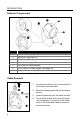
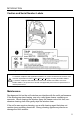
INTRODUCTION Scanner Components ITEM NO 1 2 DESCRIPTION White LED (see page 12) Blue LED (see page 12) 3 Red Output Window (Laser Aperture) 4 Speaker (see page 12) 5 6 7 Pin Hole for Cable Release 10-Pin RJ45, Female Socket (see page 28) Adjustable Scan Head, 30° Figure 1. Scanner Components Cable Removal Figure 2. Cable Release 4 1. Locate the small ‘pin-hole’ on the bottom of the scanner near the cable. 2. Bend an ordinary paperclip into the shape shown. 3.
INTRODUCTION Caution and Serial Number Labels Figure 3. Labeling Locations on the Bottom of the Scanner and Examples Caution To maintain compliance with applicable standards, all circuits connected to the scanner must meet the requirements for SELV (Safety Extra Low Voltage) according to EN/IEC 60950-1. To maintain compliance with standard CSA C22.2 No. 60950-1/UL 60950-1 and norm EN/IEC 60950-1, the power source should meet applicable performance requirements for a limited power source.
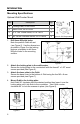
INTRODUCTION Mounting Specifications Optional Wall/Counter Mount Item Description Qty. a. Locking Plate, PN 50-50302 1 b. Base Cover, PN 50-50301 1 c. #7 x 1.00" Wood Screw, PN 18-18013 3 d. M3 x 8 mm Flathead Screw, PN 18-18004 4 Figure 4. Kit Components 1. Drill three #39 pilot holes. Note the position Orbit will rest (see Figure 5). Use the dimensions provided in Figure 5 or the locking plate as a template to drill three #39 pilot holes in the mounting surface. 2.
INSTALLATION RS232, Light Pen Emulation 1. Turn off the host device. 2. Plug the male 10-pin RJ45 end of the PowerLink cable into the 10-pin socket on the MS7120. 3. Connect the 9-pin female end of the PowerLink cable to the host device. 4. Plug the external power supply into the power jack on the PowerLink cable. Check the AC input requirements of the power supply to make sure the voltage matches the AC outlet. The outlet must be located near the equipment and be easily accessible. 5.
INSTALLATION RS485 1. Turn off the host device. 2. Plug the male 10-pin RJ45 end of the MVC cable into the 10-pin socket on the MS7120. 3. Connect the other end of the MVC cable to the host device. 4. Turn on the host device. Figure 10. When the scanner first receives power, the blue and white LED will toggle on and off then the scanner will beep once. Plugging the scanner into the serial port of the PC does not guarantee that scanned information will appear at the PC.
INSTALLATION Keyboard Wedge 1. Turn off the host device. 2. Plug the male 10-pin RJ45 end of the PowerLink cable into the 10-pin socket on the MS7120. 3. Disconnect the keyboard from the host device. 4. Connect the “Y” end of the PowerLink cable to the keyboard and the keyboard port on the host PC. If necessary use the male/female adapter cable supplied with the scanner for proper connections. 5. Plug the external power supply into the power jack on the PowerLink cable.
INSTALLATION Stand-Alone Keyboard 1. Turn off the host device. 2. Plug the male 10-pin RJ45 end of the PowerLink cable into the 10-pin socket on the MS7120. 3. Connect the other end of the PowerLink cable to the keyboard port on the host device. 4. Plug the external power supply into the power jack on the PowerLink cable. Check the AC input requirements of the power supply to make sure the voltage matches the AC outlet. The outlet must be located near the equipment and be easily accessible. 5.
INSTALLATION Full Speed or Low Speed USB 1. Turn off the host device. 2. Plug the male 10-pin RJ45 end of the USB cable into the 10-pin socket on the MS7120. 3. Plug the other end of the USB interface cable into the host device’s USB port. 4. Turn on the host device. When the scanner first receives power, the blue and white LED will toggle on and off then the scanner will beep once. Figure 13. As a default, the MS7120-38 leaves the factory with USB Keyboard Emulation Mode enabled.
SCANNER OPERATION Audible Indicators When the MS7120 is in operation, it provides audible feedback to indicate the status of the scanner. Eight settings are available for the tone of the beep (normal, six alternate tones and no tone). For instructions on how to change the tone of the beeper, refer to the MetroSelect Configuration Guide (00-02407). One Beep When the scanner first receives power the blue and white LED will toggle on and off.
SCANNER OPERATION Visual Indicators The MS7120 is equipped with a blue and a white LED that indicates the scanner’s state and the status of the current scan when the unit is in operation. Figure 14. LED Location No LEDs The LEDs will not be illuminated if the scanner is not receiving power from the host or transformer. Steady Blue When the laser is active, the blue LED is illuminated. The blue LED will remain on until the laser is deactivated. During the power save mode, the laser will turn on and off.
SCANNER OPERATION Failure Mode Indicators Flashing Blue with One Razzberry Tone This indicates that the scanner has experienced a laser subsystem failure. Return the unit to an authorized service center for repair. Synchronized Flashing of Blue and White with Two Razzberry Tones This indicates that the scanner has experienced a motor failure. Return the unit to an authorized service center for repair.
SCANNER OPERATION Depth of Field Specifications* Normal Scan Zone Specifications are based on a 0.33 mm (13 mil) bar code. Figure 15. MS7120 Normal Depth of Field Reduced Scan Zone Specifications are based on a 0.33 mm (13 mil) bar code. Figure 16. MS7120 Reduced Depth of Field * All specifications are subject to change without notice.
SCANNER OPERATION Depth of Field by Bar Code Element Width* Normal Scan Zone MINIMUM BAR CODE ELEMENT WIDTH A B C D E F G H J K mm .13 - - - .19 - .25 .33 - .66 mils 5.2 - - - 7.5 - 10 13 - 26 Figure 17. Normal Scan Zone by Bar Code Element Width * All specifications are subject to change without notice.
SCANNER OPERATION Depth of Field by Bar Code Element Width* Reduced Scan Zone MINIMUM BAR CODE ELEMENT WIDTH A B C D E F G H J K mm - .15 - - .19 - .25 .33 - .66 mils - 5.7 - - 7.5 - 10 13 - 26 Figure 18. Reduced Scan Zone by Bar Code Element Width * All specifications are subject to change without notice.
TROUBLESHOOTING GUIDE The following guide is for reference purposes only. Contact a customer service representative to preserve the limited warranty terms on page 33. Symptoms Possible Cause(s) Solution All Interfaces During power up the unit beeps three times. There is a non-volatile RAM failure. Contact a customer service representative. During power up the unit razzes once and the blue LED flashes. There is a VLD failure. Contact a customer service representative.
TROUBLESHOOTING GUIDE Symptoms Possible Cause(s) Solution All Interfaces The unit is trying to scan a particular symbology that is not enabled. The unit powers up but does not scan and/or beep. The scanner has been configured for a character length lock, or a minimum length and bar code being scanned does not satisfy the configured criteria. UPC/EAN, Code 39, Interleaved 2 of 5, Code 93, Code 128 and Codabar are enabled by default.
TROUBLESHOOTING GUIDE Symptoms Possible Cause(s) Solution All Interfaces Scanner beeps at some bar codes and NOT for others of the same bar code symbology. The bar code may have been printed incorrectly. Check if it is a check digit, character or border problem. The scanner is not configured correctly for the type of bar code. Check if check digits are set properly. The minimum symbol length setting does not work with the bar code. Check if the correct minimum symbol length is set.
TROUBLESHOOTING GUIDE Symptoms Possible Cause(s) Solution RS232 Only The host is The scanner and host receiving data may not be configured but the data does for the same interface. not look correct. Characters are being dropped. The inter character delay needs to be added to the transmitted output. Check that the scanner and the host are configured for the same interface. Add some inter-character delay to the transmitted output by using the MetroSelect Configuration Guide (PN 00-02407).
DESIGN SPECIFICATIONS MS7120 Operational Light Source: Visible Laser Diode (VLD) @ 650 nm Laser Power: Less than 1 mW average Normal Depth of Field: 0 mm – 215 mm Reduced Depth of Field: 0 mm – 190 mm Scan Speed: No. of Scan Lines: Motor Speed: Min Bar Width: 0.33 mm (13 mil) bar code 1120 scan lines per second 20 3360 RPM 0.13 mm (5.
DESIGN SPECIFICATIONS MS7120 Electrical Voltage Supply: Operating Power: Standby Power: 5VDC ± 0.25V 0.9 W 0.85 W Operating Current: 180 mA typical at 5VDC Standby Current: 170 mA typical at 5VDC DC Transformers: Class II; 5.2VDC @ 1A For regulatory compliance information, see pages 30 - 32.
APPLICATIONS AND PROTOCOLS The model number on each scanner includes the scanner number and factory default communications protocol. SCANNER VERSION IDENTIFIER COMMUNICATION PROTOCOL(S) 38 RS232 Low Speed USB, Keyboard Emulation or Serial Emulation 41 Full RS232C/Light Pen Emulation 47 Keyboard Wedge, Stand-Alone Keyboard and RS232 Transmit/Receive 106 RS485 and Full Speed USB MS7120 The MS7120 scanner with built-in PC Keyboard Wedge Interface is designed to be used for keyboard emulation only.
SCANNER CONFIGURATION CONFIGURATION MODES The MS7120* Series scanner has three modes of configuration. Bar Codes The MS7120 can be configured by scanning the bar codes located in the MetroSelect® Configuration Guide. This manual is available for download at www.honeywellaidc.com. MetroSet2 This user-friendly Windows®-based configuration program allows you to simply ‘point-and-click’ at the desired scanner options. MetroSet2 is available for download at www.honeywellaidc.com.
UPGRADING THE FIRMWARE The MS7120 is part of Honeywell’s line of scanners with flash upgradeable firmware. The upgrade process requires, a new firmware file supplied to the customer by a customer service representative and Honeywell’s MetroSet2 software. A personal computer running Windows 95 or greater with an available RS232 serial or USB port is required to complete the upgrade. PowerLink Cable #54-54014 is required when using RS232 for the upgrade process.
SCANNER AND CABLE TERMINATIONS Scanner Pinout Connections The MS7120 scanner interfaces terminate to a 10-pin modular socket. The serial number label indicates the interface enabled when the scanner is shipped from the factory. Figure 19.
SCANNER AND CABLE TERMINATIONS Cable Connector Configurations (Host End) “Standard” PowerLink Cable PN 59-59000x -3 straight Pin Function 1 Shield Ground 2 RS232 Transmit Output 3 RS232 Receive Input 4 DTR Input/Light Pen Source 5 Power/Signal Ground 6 Light Pen Data 7 CTS Input 8 RTS Output 9 +5VDC 9-Pin D-Type Connector USB Power/Communication Cable PN 54-54213x-N-3, 54-54214x-N-3 or 59-59235x-N-3 Pin Function 1 PC +5V/V_USB 2 D- 3 D+ 4 Ground Shield Shield Locking, Type A 5
SCANNER AND CABLE TERMINATIONS Cable Connector Configurations (Host End) Keyboard Wedge PowerLink Cable PN 59-59002x -3 Pin 1 2 3 4 5 Pin 1 2 3 4 5 6 Function Keyboard Clock Keyboard Data No Connect Power Ground +5 Volts DC Function PC Data No Connect Power Ground +5 Volts DC PC Clock No Connect 5-Pin DIN, Female 6-Pin DIN, Male Honeywell will supply an adapter cable with a 5-pin DIN male connector on one end and a 6-pin mini DIN female connector on the other.
REGULATORY COMPLIANCE Safety ITE Equipment IEC 60950-1, EN 60950-1 Laser Laser Class 1: IEC 60825-1:1993+A1+A2, EN 60825-1:1994+A1+A2 Caution Use of controls or adjustments or performance of procedures other than those specified herein may result in hazardous laser light exposure. Under no circumstances should the customer attempt to service the laser scanner. Never attempt to look at the laser beam, even if the scanner appears to be nonfunctional.
REGULATORY COMPLIANCE EMC Emissions: FCC Part 15, ICES-003, CISPR 22, EN 55022 Immunity: CISPR 24, EN 55024 Note: Immunity performance is not guaranteed for scanner cables greater than 3 meters in length when fully extended. Changes or modifications not expressly approved by the party responsible for compliance could void the user’s authority to operate the equipment. Class A Devices The following is applicable when the scanner cable is greater in length than 3 meters (9.
REGULATORY COMPLIANCE Standard Europeo Attenzione Questo e’ un prodotto di classe A. Se usato in vicinanza di residenze private potrebbe causare interferenze radio che potrebbero richiedere all’utilizzatore opportune misure. Attention Ce produit est de classe “A”. Dans un environnement domestique, ce produit peut être la cause d’interférences radio. Dans ce cas l’utiliseteur peut être amené à predre les mesures adéquates.
LIMITED WARRANTY Honeywell International Inc. ("HII") warrants its products and optional accessories to be free from defects in materials and workmanship and to conform to HII’s published specifications applicable to the products purchased at the time of shipment.
PATENTS This Honeywell product may be covered by, but is not limited to, one or more of the following U.S. Patents: U.S. Patent No.
INDEX A host ....................................... 18–21 AC .................................. see power accessories ...............................2, 3 adapter ....................................9, 34 I B bar code ......................................30 bar width......................................22 beep ............................see indicator blue .............................see indicator C cable communication. 2, 3, 4, 7–11, 33– 34 pin assignments........... 32, 33–34 caution...............
INDEX P patents.........................................39 pin assignments cable ..................................33–34 scanner ....................................32 port .............................. 7–11, 18–21 power .................. 2, 3, 7–11, 22, 23 PowerLink........................ see cable protocol........................................24 R razz .............................see indicator RMA ............................................38 RS232 ........................ see interface RS485 .....
CUSTOMER SUPPORT Technical Assistance If you need assistance installing or troubleshooting your device, please call your distributor or the nearest technical support office: North America/Canada Telephone: (800) 782-4263 E-mail: hsmnasupport@honeywell.com Latin America Telephone: (803) 835-8000 Telephone: (800) 782-4263 E-mail: hsmlasupport@honeywell.com Brazil Telephone: +55 (21) 3535-9100 Fax: +55 (21) 3535-9105 E-mail: brsuporte@honeywell.
CUSTOMER SUPPORT Product Service and Repair Honeywell International Inc. provides service for all its products through service centers throughout the world. To obtain warranty or non-warranty service, contact the appropriate location below to obtain a Return Material Authorization number (RMA #) before returning the product. North America Telephone: (800) 782-4263 E-mail: hsmnaservice@honeywell.
Honeywell Scanning & Mobility 90 Coles Road Blackwood, NJ 08012 00-02282 Rev E October 2009