C4D-4MUSAA_V8 - INSTALLATION GUIDE V 1.
Table of contents Preface ...................................................................................................................................3 Warnings and notices ............................................................................................................3 FCC Regulations ........................................................................................................... 3 FCC RF Exposure Information (SAR) ..............................................................
Preface The information contained in this installation guide is subject to changes in order to improve the reliability, design or features without prior notice. MUNIC Car Data reserves the right to make changes in the content without obligation to notify any person or organisation of such changes or improvements.
FCC RF Exposure Information (SAR) This device is designed and manufactured not to exceed the emission limits for exposure to radio frequency (RF) energy set by the Federal Communications Commission of the United States. During SAR testing, this device is set to transmit at its highest certified power level in all tested frequency bands. Although the SAR is determined at the highest certified power level, the actual SAR level of the while operating can be well below the maximum value.
1.
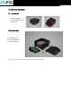
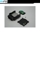
2. Hardware description 2.1. External view 1 : OBD connector 2 : micro USB connector 3 : bicolor led 3 2 1 2.2.
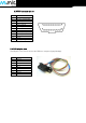
2.3 OBD connector pin out Pin # 1 2 3 4 5 6 7 8 10 11 14 15 16 Comment OEM specific J1850+ (PWM/VPW) OEM specific Chassis ground Signal ground CAN High K line OEM specific J1850- (PWM) OEM specific CAN low L line Battery voltage 2.4 OBD adapter wires This adapter is only used to connect the OBD to a computer (laptop/desktop).
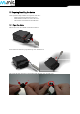
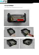
3. Preparing/installing the device Those operations may need the use of specific tools like : - Small cross-head screwdriver for the screw. - Small slotted screwdriver to remove the cover. - Thin tweezers to insert/remove the SIM card. 3.1. Open the device Remove the screw using Small cross-head screwdriver Insert slotted screwdriver to pop-out the top cover and extract it.
Device is now open
3.2. Insert the SIM card The micro SIM card slot is located between the two electronic cards. Insert the card with contact on bottom into the slot and push it as far as it will go.
3.3. Properly close the device First, check that the hole of the electronic card is correctly inserted in the plastic part. If it’s not inserted please move smoothly the electronic cards right and left to place it in correct position. GOOD Second, insert the GPS antenna as shown below.
Second, check that the micro USB port is correctly inserted on its place. If it’s not inserted please move smoothly the electronic cards to place it in correct position.
insert the GPS antenna as shown below. Finally, insert the battery and place the screw. 3.4. Install the OBD Dongle Connect the OBD Dongle on your vehicle OBD connector.
4. LED sequences The Dongle has a two-coloured LED, green and red. When both colours are brightened, you can see an orange light. Sequence Green LED Meaning No Modem /No GNSS No Modem /Fix GNSS Modem OK /No GNSS Modem OK /Fix GNSS 3 times (50ms ON/100ms OFF) 3550ms OFF 2 times (50ms ON/100ms OFF) 3700ms OFF 1 time (50ms ON/100ms OFF) 3850ms OFF 2000ms ON 2000ms OFF Sequence Dongle OFF Red LED Meaning OFF Ext. Power/Run ON Shutdown/Hibernate Idle/Sleep 30ms ON / 1 s OFF 30ms ON / 1 s OFF 5.