
Installation Sheet
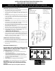

Fig.1
INSTALLATION INSTRUCTIONS FOR N7869-678-L
READ AND SAVE THESE INSTRUCTIONS
WA R N I N G ! S H U T P O W E R O F F AT F U S E O R C I R C U I T B R E A K E R
A V E R T I S S E M E N T ! C O U P E R L E C O U R A N T A U N I V E A U D E S F U S I B L E S O U D O D I S J O N C T E U
PREPARING FOR INSTALLATION (Fig. 1)
1. Shut off power at the fuse box or circuit breaker box and remove
the old fixture including the mounting hardware.
2. Carefully unpack your new fixture and lay out all the parts in a clean
area. Take care not to misplace any small parts necessary for
installation.
3. Determine the desired hanging height and thread rods (L, M, and N)
to the all threads on the fixture body. Then attach loop (K) by
screwing into rod (L). Note: Pass the wires carefully through each
rod as you assemble.
4. Screw the all thread (F) into the ceiling loop (G) and secure with nut
(B) until tight.
5. Thread the other end of the all thread into the crossbar (C) and
secure with nut (B) until tight. Note: The length of the all thread
into the crossbar (C) may be adjusted if necessary.
6. Take crossbar assembly and secure to outlet box (A), not included,
with mounting screw (E) (Size: #8-32N*L5/8”). The side of crossbar
marked with “GND” must face out.
7. Slide lock collar (I) and canopy (H) over loop (K). Then attach the
quick link (J) to loop (K) and to ceiling loop (G). Close quick link (J).
8. Carefully feed the fixture wires and ground wire through the loop
(K), quick link (J), ceiling loop (G), and all thread (F).
CONNECTING THE WIRES (Fig.2)
9. Connect the electrical wires as shown in figure 2, making sure that
all wire connectors are secured. If your outlet box (A) has a ground
wire (green or bare copper), connect the fixture’s ground wire to it.
Otherwise, connect the fixture’s ground wire directly to the
crossbar (C) using the green screw provided.
COMPLETING THE INSTALLATION (Fig. 1)
10. Tuck the wire connectors neatly into the ceiling outlet box (A), not
included. Raise the canopy (H) to the ceiling and secure with the
lock collar (I) to the ceiling loop (G).
11. Secure the crystals (S) onto the tube (O) with wrench (Q), included,
and screws (P).
REPLACING LED MODULE (Fig. 1)
The LED module can be replaced by a qualified electrician
without cutting the wire and without damage to any
decorative element to which the fixture is attached. See
installation steps for more details (Fig.1).
a. Shut off the power.
b. Remove the screw (e) use wrench (f) (same as Q) then unscrew
socket tube (g) from fixture.
c. Press the bottom of the printed “L” quick connector on LED
module (d) with screwdriver (a), not included, to disconnected the
black wire and then disconnect the white wire from the printed
“N” quick connector on LED module (d).
d. Remove the screws (b) with screwdriver (a). Carefully remove the
LED module (d).
e. Reverse steps b-d for installing the new LED module (d).
Your installation is now completed. Return power to the outlet box and
test the fixture
Note: Illustration (Fig.1) on this manual is for installation
purposes only. It may or may not be identical to the fixture
purchased.
Dimmable with ELV and/or LED compatible wall dimmer.
Fig.2
Set-Mounting# A-014
-Crossbar (1)
-Green screw (1)
-Mounting screw (2)
Rod#W35-H-66*1(L)
#W35-1-66*3(M)
#9N7869678RD10*1(N)