Operating Instructions METTLER TOLEDO AX and MX/UMX Balances
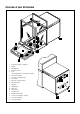
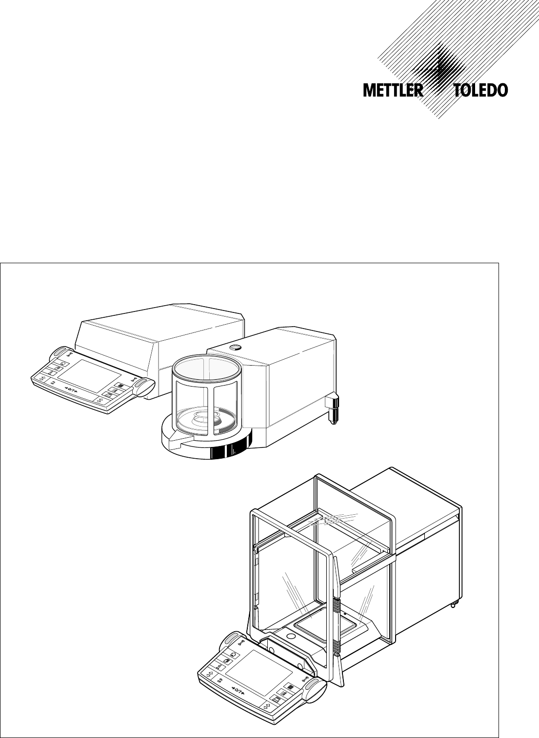
Overview of your AX balance 10 11 9 12 4 15 8 13 14 7 3 2 6 1 4 3 3 5 1 Terminal (for details s.
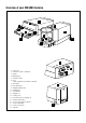
Overview of your MX/UMX balance 1 19 11 5 2 4 3 4 12 5 4 8 10 6 13 9 7 1 17 1 Control unit 2 Terminal (for details s.
Contents 4 Contents 1 Getting to know your balance .......................................................................................................................... 9 1.1 1.2 1.3 1.4 Introduction .................................................................................................................................................... 9 Introducing the AX and MX/UMX balances ..........................................................................................................
Contents 5 5.12 5.13 5.14 5.15 Selecting the dialog language ......................................................................................................................... 35 Security settings ............................................................................................................................................ 36 Energy-saving function and battery change date ...............................................................................................
Contents 6 8 The “Density” Application ............................................................................................................................. 63 8.1 8.2 8.3 8.3.1 8.3.2 8.3.3 8.3.4 8.3.5 8.3.6 8.3.7 8.3.8 8.4 8.4.1 8.4.2 8.4.3 8.4.4 8.4.5 8.5 8.5.1 8.5.2 8.5.3 Introducing the “Density” application ............................................................................................................... 63 Selecting the application ..............................................
Contents 7 12 Technical data and accessories ..................................................................................................................... 86 12.1 12.2 12.3 12.4 12.5 General data ................................................................................................................................................. 86 Model-specific data .......................................................................................................................................
Contents 8
Chapter 1: Getting to know your balance 9 1 Getting to know your balance In this chapter you will be given basic information about your balance. Please read right through this chapter carefully even if you already have experience with METTLER TOLEDO balances; please pay special attention to the safety warnings! 1.1 Introduction Thank you for choosing a METTLER TOLEDO balance.
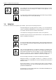
Chapter 1: Getting to know your balance 10 These symbols indicate safety notes and hazard warnings which, if ignored, can cause personal danger to the user, damage to the balance or other equipment, or malfunctioning of the balance. This symbol indicates additional information and notes which make using your balance easier, and help you to use it correctly and efficiently. 1.
Chapter 2: Setting up the balance 11 2 Setting up the balance This chapter explains how to unpack your new balance, and how to set it up and prepare it for operation. When you have carried out the steps described in this chapter, your balance is ready for operation. 2.1 Unpacking and checking the delivered items When you receive the balance, please check that all parts have been delivered. Open the packaging and carefully remove all the parts.
Chapter 2: Setting up the balance 12 2.3 Selecting a location and leveling the balance Your balance is a precision instrument. Its accuracy and reliability depend on its being placed in an optimal location: Choose a position which is stable, free from vibration, and as nearly horizontal as possible. The supporting surface must be able to bear the weight of the fully loaded balance safely. A stone table is recommended for MX/UMX balances. Pay attention to the environmental conditions (see technical data).
Chapter 2: Setting up the balance 13 2.5 Glass draft shield The glass draft shield of your balance can be adapted to the environmental conditions and your weighing style, as well as to the type of weighing and loading. Draft shield on AX balances The position of the coupling elements determines which parts (left-hand, right-hand, and upper door) of the glass draft shield can be opened. Try out various different combinations by moving the 4 coupling elements up and down.
Chapter 2: Setting up the balance 14 2.6 Adjusting the reading angle and positioning the terminal So that you can work without fatigue, the reading angle of the terminal can be adjusted. For delivery, the terminal is fastened to the balance or control unit. So that you can arrange your workplace optimally, the terminal can be disconnected from the balance or control unit and positioned separately.
Chapter 2: Setting up the balance 15 Pull the connecting cable gently out of the tension relievers. Unwind the cable. Replace the cover and fasten it with the knurled screw. Fold the terminal forward again into its normal position. Grasp the back of the terminal and pull it slowly upward until it clicks into the top position (steepest reading angle). Press the two stop buttons on the back of the terminal and pull the terminal further upward.
Chapter 2: Setting up the balance 16 MX/UMX balances Switch off the balance and unplug the cable of the AC adaptor, and any interface cables, from the control unit. It is not necessary to disconnect the control unit from the weighing cell. Grasp the control unit and weighing cell by the sides of the housing and carry them to their new location (observe the notes in Chapter 2.3 regarding the choice of an optimal location).
Chapter 3: Simple weighing 17 3 Your first weighing In this chapter you will get to know the operating and display elements of your balance which are necessary to carry out simple weighings. This chapter provides a first introduction to operating your balance. 3.1 Switching the balance on and off On To switch the balance on: Briefly touch the «On/Off» key. After the balance has been switched on, it carries out a short test and is then ready for weighing.
Chapter 4: Basic operating concepts for the terminal and software 18 4 Basic operating concepts for the terminal and software This chapter describes the operating and display elements on your terminal and explains the concept for operating the software on your balance. Please read right through this chapter carefully: it is the basis for all the operating steps described in subsequent chapters. 4.
Chapter 4: Basic operating concepts for the terminal and software 19 6 5 «6» key Before leaving the factory, your balance has been programmed with standard applications (e.g. for normal weighing, piece counting, and density determination). Use this key to select the application you wish to work with. 7 6 «7» key Each application has a large number of settings which can be used to adapt it optimally to the specific task. Use this key to call up the menus to configure the currently active application.
Chapter 4: Basic operating concepts for the terminal and software 20 4.3 The software on your balance The software controls all the functions of your balance. It also makes it possible to adapt the balance to your specific working environment. Please read the following sections carefully; they form the basis for operating your balance.
Chapter 4: Basic operating concepts for the terminal and software 21 The diagram below shows the interrelationships between the individual levels of the software and gives a first overview of the typical procedure for operating it. Example Work step 1. Select user profile 3 or 4 or 6 4 ▼ 4 ....... 4 “Home” 2. Select application ▼ 6 6 or or 6 3. Work 7 ▼ ▼ 4. If desired: Change the settings for the selected application (applicationdependent settings) • 5.
Chapter 4: Basic operating concepts for the terminal and software 22 4.4 Typical working procedure Following below is a brief description of the typical working procedure, leaving out details which depend on specific applications. On Off Switch on the balance: Switch on the balance by briefly pressing the «On/Off» key. After the balance has been switched on, it is in the “Home” profile of the “Weighing” application.
Chapter 4: Basic operating concepts for the terminal and software 23 7 – System settings apply for the entire weighing system and for all applications. They are also stored in the active user profile (which is shown in the title line). Check that the desired user profile is active before you change any system settings! Note: The system settings can also be accessed from the application menu («6» key). The system settings are described in detail in Chapter 5.
Chapter 5: System settings 24 5 System settings In this chapter you will learn how you can adapt the weighing system to your requirements. There are system settings for each user profile, as well as for the “Home” profile. As long as a particular user profile is active, its system settings apply irrespective of which application is being used. Note: You will learn the settings for the different applications when the applications are described. 5.
Chapter 5: System settings 25 5.3 Settings for adjustment and test You can use these menus to make all the settings associated with adjusting (calibrating) your balance. In the sections below you will find information on all the possible settings for adjustment and test procedures and for recording them. 5.3.1 Displaying the adjustment history (“History”) In the “History” menu you can call up information on adjustment procedures which have already been carried out, and print out corresponding reports.
Chapter 5: System settings 26 5.3.2 Defining adjustment and test reports In this menu, which has two pages, you can specify the information to be printed on the adjustment and test reports. By touching the appropriate buttons, you can activate the desired information. The checked items of information will be included on the reports. By touching “STD” you can return to the factory settings. To save the changes, touch “OK”, (or touch “C” to quit the input window without saving the changes).
Chapter 5: System settings 27 5.3.3 “ProFACT” fully automatic adjustment function In this menu you can specify the settings for fully automatic adjustment (calibration) using the internal adjustment weight (“ProFACT”). ProFACT adjusts the balance fully automatically on the basis of pre-selected criteria. The following settings are available: “Protocol trigger” Here you specify which adjustment procedures should be automatically printed on the report.
Chapter 5: System settings 28 5.3.4 Defining an external adjustment weight If you work with an external adjustment weight, you can define its weight and unit here. (Note: Depending on country-specific regulations, this function may not be available for certified balances). An input window appears which looks like a pocket calculator and can be used like one. Enter the weight of the external adjustment weight. Check the weighing unit: it is shown to the right of the weight.
Chapter 5: System settings 29 5.4 Specifiying the weighing parameters “Weighing mode” You can use this setting to match the balance to the type of weighing. Select weighing mode “Normal” for all normal weighing processes, or “Dosing” for dispensing liquid or powdery weighing samples. With this setting the balance responds very quickly to minutest changes in weight. The “Hi-Resolution” setting is not available on all balances.
Chapter 5: System settings 30 5.5 “SmartSens” settings “SmartSens left”, “SmartSens right” You can use this setting to define the function of the left-hand and right-hand “SmartSens” sensors. 1 – “Off”: SmartSens is inactivated – “Door”: Opens/closes the glass draft shield (on MX/UMX balances you can also choose whether the draft shield should open to the left or right).
Chapter 5: System settings 31 5.7 Selecting the door function “Door Function” The automatic door function eases your work by making the doors of the glass draft shield open or close automatically whenever specific functions require them to do so. For example, the glass draft shield opens automatically after zeroing or taring, and prompts you to put the material for weighing, or the tare weight, onto the weighing pan.
Chapter 5: System settings 32 5.8 Selecting peripheral devices Various peripheral devices can be connected to your balance. In this menu you can specify which device should be connected. Important: In contrast to the other system settings, these settings apply to all user profiles.
Chapter 5: System settings 33 5.9 Terminal settings “Brightness” Here you can set the brightness of the display. Touch the arrow buttons to adjust the brightness in the range 0% to 100% as required. Each time one of the two arrow buttons is touched, the brightness is instantly adjusted so that the change can be seen immediately. Factory setting: 80% “Contrast” Sets the contrast of the display in the range 0% to 100%. Adjustment is done in the same way as for brightness.
Chapter 5: System settings 34 5.10 Resetting to the factory settings Here you can reset all the settings to the factory settings. Important: Resetting affects all the settings (application-dependent settings and system settings) for the active user profile! If you select “Set”, for safety reasons you will be asked whether you really want to reset to the factory settings. Select either “OK” to reset to the factory settings or “C” to keep the existing settings. 5.
Chapter 5: System settings 35 “Date” Sets the current date. An input window appears which looks like a pocket calculator and can be used like one. Enter the current date in format day–month–year (DD.MM.YYYY), irrespective of which date format you selected for the display. Note: You can also make this adjustment directly in weighing mode by touching the date. A window appears in which you can enter the date directly.
Chapter 5: System settings 36 5.13 Security settings “Password” Here you can specify the password for the current user profile. The password protects the following areas of the current user profile: – Access to the system settings – Calling up the user profile. If one of these areas is called up, the corresponding password must first be entered. Note: If a password is defined for the “Home” profile, it only protects access to the system settings.
Chapter 5: System settings 37 5.14 Energy-saving function and battery change date “Standby” Here you can specify how long the balance can remain unused before it switches over to “Standby” mode. “Standby” mode is the same status as when the balance is switched off with the «On/Off» key. To switch the balance on again, the «On/Off» key has to be pressed.
Chapter 6: The “Weighing” application 38 6 The “Weighing” Application In this chapter we will introduce you to the “Weighing” application. You will find information for practical work with this application, and about the application-specific settings that are available (you will find information about non-application-specific system settings in Chapter 5). 6.1 Selecting the application If the “Weighing” application is not already active, touch the «6» key.
Chapter 6: The “Weighing” application 39 Touching the buttons with the arrow symbols returns you to the second menu page. “Display Unit”: Specifies the unit for displaying the results (Section 6.2.6). “Info Unit”: Specifies an additional weighing unit to be displayed as an information field in the display (Section 6.2.6). “Custom Unit 1”: Defines Custom Unit 1 (Section 6.2.7). “Custom Unit 2”: Defines Custom Unit 2 (Section 6.2.7).
Chapter 6: The “Weighing” application 40 6.2.2 Select function keys Function keys make it possible for you to access certain functions and settings of the application directly. The function keys are displayed within the application at the bottom edge of the display (see Section 4.2). Touching a key initiates the corresponding function. In this menu you specify which function keys should be available in the application.
Chapter 6: The “Weighing” application 41 6.2.3 “SmartTrac” and stopwatch “SmartTrac” is a graphical weighing-in aid which makes it easier for you to weigh in to a specified target value. “SmartTrac” appears in the application at the right-hand side of the display below the weighing result (Section 4.2). In this menu you can select the display mode for “SmartTrac” or switch it off. Instead of “SmartTrac”, you can also display a stopwatch.
Chapter 6: The “Weighing” application 42 “–Tol” and “+Tol”: These information fields show the tolerances on the target weight that were input using the function keys with the same name (Section 6.3.3). “n”, “x”, “s”, “s.rel”, “Sum”, “T+”, “Min”, “Max” and “Diff” These information fields show the following statistical values: “n”: “x”: “s”: “s.
Chapter 6: The “Weighing” application 43 6.2.6 Selecting weighing units In the “Display Unit” and “Info Unit” menus, you specify which weighing units you wish to work with. By choosing different units, you can have the weighing result displayed in two different weighing units simultaneously. The same selection of units is available for both the “Display Unit” and the “Info Unit”.
Chapter 6: The “Weighing” application 44 6.2.8 Defining the weighing record In this menu you specify the information to appear on the weighing reports. To make it clearer, this extensive menu is divided into 3 submenus in which you can specify the options for the title of the record, recording the individual values, and the weighing result. Options for the record titles In this submenu, which has two pages, you specify the information to be printed in the title of the weighing record.
Chapter 6: The “Weighing” application 45 Options for recording the individual values In this submenu you specify the information to be printed on the record for each individual weighing result. Factory setting: Single values are printed with no further information. The following items of information relating to individual values are available to be printed on the weighing records: “ID1”, “ID2” and “ID3”: The identifications entered using the function keys with the same names are printed out (Section 6.3.
Chapter 6: The “Weighing” application 46 On the second page of the menu, the following information items for the record of the end result are available: 6.2.9 “Diff”: Difference between the lowest and highest weight of the weighing serie. “Sum”: Sum of all individual weights. “Visum”: Adds an extra line to the record for a signature. Parameters for manual record printing You can use the settings in the “Print key” menu to specify the behavior of the «8» key (print report).
Chapter 6: The “Weighing” application 47 6.2.10 Defining identifications and record titles In the “Identification” menu you specify titles for the weighing records and designations for the identifications. An identical alphanumeric input field is available for all types of input (shown illustrated at right). “Title 1” and “Title 2” : The designations entered appear in the title of the weighing records. The maximum length of the record title is 20 characters.
Chapter 6: The “Weighing” application 48 6.2.11 Parameters for processing bar code data If there is a bar code reader connected to your balance, you can specify in the “Bar code input” menu how this data should be processed. The following settings can be selected: “ID1”, “ID2”, and “ID3”: The captured data is treated as identification text and assigned to the corresponding identification (Section 6.3.6). Note: Instead of “ID1”, “ID2”, and “ID3”, the specified designations are displayed (Section 6.2.10).
Chapter 6: The “Weighing” application 49 Key the desired tare value in. Check the weighing unit: this is displayed to the right of the tare value. If you touch the weighing unit, the units available for selection are displayed. Note: The units are not converted automatically, i.e. if you input a value in a particular unit, this value remains, even if you change the weighing unit. After you have entered the value, touch “OK” to activate the tare preset.
Chapter 6: The “Weighing” application 50 When one or other of the function keys for the minus or plus tolerance is touched, the window for entering the corresponding value appears. The input window is the same as for the target value. Here, too, check the unit which is displayed to the right of the tolerance value. You can specify the tolerance as a percentage (%) or as an absolute value in one of the available weighing units. After you have input the respective value, touch “OK” to activate the tolerance.
Chapter 6: The “Weighing” application 51 SmartTrac 4 The target value is represented by the vertical line. During weighing-in, triangular segments appear to the left and right of this line, which disappear toward the point at the top as the fine range is approached. When the fine range is reached, a pointer appears which makes precise fine-dispensing to the target value easy. SmartTrac 5 The target value is represented by the vertical line located between the two tolerance marks.
Chapter 6: The “Weighing” application 52 Place the first sample on the weighing pan and wait until the stability detector is extinguished. Touch the “M+” function key to accept the weight into the statistics. The weight value measured is then printed out. Note: If you have activated automatic weight transfer (Section 6.2.5) the weight is accepted automatically as soon as the value becomes stable. If you have activated the automatic door function (Section 5.
Chapter 6: The “Weighing” application 53 ------- Statistics ----Nominal 215.500 g -Tol 1.5 % +Tol 2.5 % 1 2 3 4 5 n T+ x sd rsd Min Max Diff Sum 214.3149 214.3144 215.1928 215.9100 216.0705 g g g g g 215.16052 0.83853 0.39 214.3144 216.0705 1.7561 1075.8026 5 2 1 g g % g g g g Visum You can produce the record for the weighing results by touching the “Print” key. The illustration on the left shows an example of a record.
Chapter 6: The “Weighing” application 54 The example on the left shows the balance display after the ID function keys, and the ID information fields, have been activated. The practical example described below is based on the designations shown in the illustration above. In the application, when you process a job for a client, and when weighing is complete, touch the “ID1” (“Client”) function key and a field appears to input the client (see illustration at left).
Chapter 6: The “Weighing” application 55 6.4 Adjusting the balance and checking the adjustment At the factory your balance was set for fully automatic adjustment using ProFACT. ProFACT adjusts and linearizes the balance automatically as soon as a change in environmental conditions makes it necessary. However, you can also carry out a manual adjustment and/or check using the internal weight, or an external weight, at any time.
Chapter 6: The “Weighing” application 56 "An error has occurred while adjusting and the adjustment has been terminated." This message also appears if you terminate the adjustment yourself. You can repeat the adjustment process or return to the application by touching “OK”. 6.4.3 Adjustment using an external weight By touching this function key, you start adjustment (calibration) of the balance using an external calibration weight.
Chapter 6: The “Weighing” application 57 The balance confirms successful completion of the adjustment. Touch “OK” to return to the application. If a printer is connected to the balance, a record of the adjustment is automatically printed according to the system settings you made for adjustment and test (Section 5.3). An example of an adjustment record is shown in Section 6.4.6.
Chapter 6: The “Weighing” application 58 6.4.6 Adjustment and test records (examples) Record of an internal or ProFACT adjustment Record of an external adjustment - Internal adjustment — 17.Apr 2000 11:51 - External adjustment — 17.Apr 2000 11:55 METTLER TOLEDO User METTLER TOLEDO User User 3 Type AX204 SNR 1234567890 Balance Lab. RF/1A Weight ID A200-F1/1 Certificate No. MT 414A Temperature 24.3 °C User 3 Type AX204 SNR 1234567890 Balance Lab. RF/1A Weight ID A200-F1/1 Certificate No.
Chapter 6: The “Weighing” application 59 Adjustment history record –––——— History ————––– 17.Apr 2000 12:02 METTLER TOLEDO User User 3 Type AX204 SNR 1234567890 Balance Lab. RF/1A Weight ID A200-F1/1 Certificate No. MT 414A 01 17.Apr 2000 10:04 internal 23.8 °C 02 17.Apr 2000 10:19 internal 23.8 °C 03 17.Apr 2000 10:39 internal 24.0 °C 04 17.Apr 2000 10:49 internal 24.0 °C . . . 50 22.Apr 2000 16:51 internal 23.
Chapter 7: The "Percent Weighing" Application 60 7 The "Percent Weighing" Application In this chapter we will introduce you to the "Percent Weighing" application. You will find information for practical work with this application and about the application-specific settings that are available (you will find information about non-application-specific system settings in Chapter 5). 7.
Chapter 7: The "Percent Weighing" Application 61 The following settings are available for the "Percent Weighing" application: With only a few exceptions, these settings are identical to those for the "Weighing" application (Section 6.2). Only the settings that are different are described below. These are in the following menus: “Function keys”: Additional function keys are available for percent weighing. “Info field”: Additional information fields are available for percent weighing.
Chapter 7: The "Percent Weighing" Application 62 7.3.4 Additional unit for percent weighing In the menus “Display Unit” and “Info Unit” there is the additional setting “%” (percent). 7.3.5 Special record information for percent weighing In the submenu with the options for recording the individual values you have additional settings for percent weighing: “Reference%”: The reference value in percent is printed on the report.
Chapter 8: The “Density” Application 63 8 The “Density” Application In this chapter we will introduce you to the “Density” application. You w ill find information for practical work with this application and about the application-specific settings that are available (you will find information about non-application-specific settings in Chapter 5). 8.
Chapter 8: The "Density" Application 64 8.3 Settings for the “Density” application A number of application-specific settings are available for density determination which you can use to adapt the application to your needs. Note: Your settings apply for the currently active user profile. Make sure that the desired profile has been selected before you make the settings. 8.3.1 Overview The application-dependent settings can be accessed with the «7» key.
Chapter 8: The “Density” Application 65 8.3.3 Selecting the auxiliary liquid In this menu you can specify the auxiliary liquid you wish to work with. This setting is only relevant if you are determining the density of solids! You can choose from the following auxiliary liquids: “Water”: Distilled water is used as the auxiliary liquid. The density of distilled water at various different temperatures is stored in the balance (density table from 10 °C to 30 °C) so it need not be known.
Chapter 8: The "Density" Application 66 On the last page of the menu there are the following function keys for density determination: “Sample ID”: You can use this function key to assign an identification to each sample whose density you determine, so you can identify it unambiguously when the results are displayed. “Sample No.”: You can use this function key to assign a number to each sample whose density you determine. This makes it easier to identify the individual samples of a sequence.
Chapter 8: The “Density” Application 67 8.3.6 Special record information for density determination In the “Protocol” menu there are special settings available for density determination. In the submenu with the options for reporting the individual values you have additional settings for density determination: “Sample ID”: Identification of the samples. “Sample No.”: Numbers of the samples. “Method”: Selected method of density determination. “Aux.
Chapter 8: The "Density" Application 68 8.3.8 Specifying the number of decimal places for the result In the ”Density decimal points” you can specify the number of decimal places for displaying the result of the density determination. You can choose between the following settings: “1” ... “5”: The result of the density determination is shown in the corresponding information field and on the reports with the number of decimal places selected. Factory setting: 8.4 “3”.
Chapter 8: The “Density” Application 69 If you use an auxiliary liquid other than water or ethanol, activate the function key “Density AL” and use this key to enter the density of the auxiliary liquid being used at the current temperature. This is necessary because there are no density tables in the balance for liquids other than water and ethanol. The value entered appears in the information field with the same name, which you should also activate.
Chapter 8: The "Density" Application 70 8.4.2 Determining the density of liquids using a sinker To determine the density of liquids, use is often made of a sinker whose volume is known. The sinker is first weighed in air, and then in the liquid whose density is to be determined. The difference in weight gives the buoyancy force which is used by the software to calculate the density. In the application-specific settings, for the method select “Liquid” (Section 8.3.2).
Chapter 8: The “Density” Application 71 8.4.3 Determining the density of pasty substances using a gamma sphere The density of pasty substances is usually determined using a gamma sphere whose volume is known. The pasty substance is weighed first without, and then with, the gamma sphere. In the application-specific settings select the method “Gamma sphere” (Section 8.3.2). Activate the suitable function keys and information fields (Sections 8.3.4 and 8.3.5).
Chapter 8: The "Density" Application 72 8.4.4 Determining the density of liquids using a pycnometer The density of liquids is often determined using a pycnometer, which is a glass container whose own capacity and weight are known. The liquid is poured into the pycnometer and weighed. In the application-specific settings select the method “pycnometer” (Section 8.3.2). Activate suitable function keys and information fields (Sections 8.3.4 and 8.3.5).
Chapter 8: The “Density” Application 73 8.4.5 Determining the density of porous solids To determine the density of porous solids the solid is first weighed in air. In contrast to non-porous solids this requires additional use of an oil bath which seals the pores of the solid with oil before it is weighed in the auxiliary liquid. In the application-specific settings select the method “Solid porous” (Section 8.3.2) and specify the desired auxiliary liquid (Section 8.3.3).
Chapter 8: The "Density" Application 74 After a short pause you will be prompted to immerse the oil-soaked solid in the auxiliary liquid. If you are working with the below-the-balance hanger, place the container with the auxiliary liquid beneath the hanger. If you are working with the optional density kit, follow the instructions delivered with the kit. In either case, ensure that the solid is immersed at least 1 cm in the liquid and that there are no air bubbles in the container.
Chapter 8: The “Density” Application 75 8.5.2 Printing out the result of a density determination You can use the «8» key to print out the result of the current density determination. Shown at left is an example of a report together with explanatory notes. ------ DENSITY ----Mettler-Toledo GmbH LAB RF 08.Jun 2000 User Type SNR Balance User 6 In this density determination the identification keys have also been used which you already know from the “Weighing” application (Section 6.3.6).
Chapter 8: The "Density" Application 76 8.5.3 Using the density statistics Statistics are maintained for the density determinations. They store the last 10 results of density determinations you made and accepted into the statistics. Note: The statistics do not differentiate between the methods used for the density determinations, but simply store the last 10 results made and accepted. To use the density statistics, the two function keys “Result” and “CL Sum” must be activated (Section 8.3.4).
Chapter 9: The “Minimum Weighing” Application 77 9 The “Minimum Weighing” Application In this chapter we will introduce you to the “Minimum Weighing” application. You will find information for practical work with this application and about the application-specific settings that are available (you will find information about non-application-specific settings in Chapter 5). 9.
Chapter 9: The “Minimum Weighing” Application 78 9.3 Settings for the “Minimum Weighing” application A number of application-specific settings are available for minimum weighing which you can use to adapt the application to your needs. Note: Your settings apply for the currently active user profile. Make sure that the desired profile has been selected before you make the settings. 9.3.1 Overview The application-dependent settings can be accessed with the «7» key.
Chapter 9: The “Minimum Weighing” Application 79 9.3.3 Special information fields for minimum weighing On the first page of the information fields menu there are three additional settings for minimum weighing: “MinWeigh”: This information field shows the minimum weighing value required. The value depends on the reference tare and is programmed on the balance by the service technician. “Ref. Tare”: This information field shows the reference tare used as the basis for the required minimum weighing.
Chapter 9: The “Minimum Weighing” Application 80 9.4 Working with the “Minimum Weighing” Application In this section you will learn how to work with the “Minimum Weighing” application. When you work with “Minimum Weighing” you can, of course, also specify target values and tolerances and use statistical functions and identifications. You already know these possibilities from the “Weighing” application (Section 6.3) so they will not be described again here.
Chapter 10: Loading Applications via the Internet 81 10 Loading Applications via the Internet In the interest of our customers METTLER TOLEDO continuously develops new applications. The existing applications are also continuously developed further and improved. To make it as easy as possible for you as our customer to gain rapid benefit from these further developments METTLER TOLEDO provides the latest versions on the Internet. 10.
Chapter 10: Loading Applications via the Internet 82 10.4 Loading the application package onto your balance After you have downloaded the application package from the Internet, before you can transfer it to your balance you must connect the balance to the serial interface of your computer with the RS232 cable.
Chapter 10: Loading Applications via the Internet 83 When you have made the necessary settings and checked the connection, you can start the updating process. You do this by clicking on “Start Software Update Procedure”. Follow the instructions of the e-Loader which will guide you through the updating procedure step by step. The e-Loader will ask you whether you wish to backup the current balance settings onto your computer. We recommend you to make this backup.
Chapter 11: Further important information 84 11 Further important information 11.1 Error messages occurring during normal operation Most error messages appear in plain text directly in the respective application, and usually accompanied by a text describing how to correct the error. Error messages of this type are self-explanatory and therefore not mentioned below.
Chapter 11: Further important information 85 11.3 Cleaning and service Periodically clean the weighing pan, the draft cover, the housing, and the terminal of your balance using the brush supplied with it. To clean the weighing chamber thoroughly, pull the draft cover and/or draft disk (which on the UMX balance is made up of several parts) and the weighing pan vertically up and off (on the MX/UMX balances it may be necessary to turn the weighing pan slightly to remove it).
Chapter 12: Technical data and accessories 86 12 Technical data and accessories In this chapter you will find the most important technical data for your balance. Accessories from the METTLER TOLEDO range increase the functionality of your balance and open up additional areas of application. In this chapter you will find a list of the options currently available. 12.1 General data Power supply • Power supply connector with AC/DC adapter: Primary: 100-240V, -15%/+10%, 50/60Hz, 0.
Chapter 12: Technical data and accessories 87 12.2 Model-specific data Data for the AX balances AX26 Comparator AX26DR AX205 AX205DR AX105DR 1 µg 2 µg 0.01 mg 0.01 mg 0.01 mg –– 0.01 mg –– 0.1 mg 0.1 mg 22 g 3g 220 g 81 g 31 g –– 21 g –– 220 g 110 g 0 .. 22 g 0 .. 21 g 0 .. 220 g 0 .. 220 g 0 .. 110 g 2 µg 4 µg 0.03 mg 0.04 mg 0.04 mg –– –– 0.015 mg 0.015mg 0.015mg Over the entire range ±6 µg ±8 µg ±0.1 mg ±0.15 mg ±0.15 mg Within 500 mg ±4 µg ±6 µg ±0.
Chapter 12: Technical data and accessories 88 Model-specific data for AX balances (continued) AX204 AX304 AX504 AX504DR 0.1 mg 0.1 mg 0.1 mg 0.1 mg –– –– –– 1 mg 220 g 310 g 510g 81 g –– –– –– 510 g 0 .. 220 g 0 .. 310 g 0 .. 5100 g 0 .. 510 g 0.07 mg 0.1 mg 0.1 mg 0.2 mg –– –– –– 0.1 mg ±0.2 mg ±0.3 mg ±0.4 mg ±0.5mg –– –– –– ±0.4 mg 2 .. 5 s 2 .. 5 s 3 .. 6 s 2 .. 4 s –– –– –– 3 ..
Chapter 12: Technical data and accessories 89 Data for MX/UMX balances UMX2 MX5 UMX5 Comparator 0.1 µg 1 µg 0.1 µg 2100 mg 5100 mg 5100 mg 0 .. 2100 mg 0 .. 5100 mg 0 .. 5100 mg At full load 0.25 µg 0.9 µg 0.4 µg In range 0 .. 2 g 0.25 µg 0.8 µg 0.25 µg In range 2.. 5 g –– 0.9 µg 0.4 µg ±1 µg ±4 µg ±4 µg ±0.5 µg ±2 µg ±2 µg 10 .. 16 s 9 .. 12 s 15 .. 20 s 2 2 2 Selectable Selectable Selectable Temperature drift (10 .. 30 °C) ±1.0 ppm/°C ±1.0 ppm/°C ±1.
Chapter 12: Technical data and accessories 90 12.3 Dimensions Dimensions of the AX balances 170 151.5 90.6 60 48 155.5 222 293 239 69 9.5 10.9 190 305.
Chapter 12: Technical data and accessories 91 Dimensions of the MX/UMX balances 35.5 42 53 113.5 260 174 26 287.5 67.5 128 116 100 ° 80 114 4 10 220 365.5 127.5 150 30 5.8 60 94 210 88 155.
Chapter 12: Technical data and accessories 92 12.4 Specifications of the RS232C interface Interface type: Voltage interface according to EIA RS-232C/DIN 66020 (CCITT V24/V.28) Max. cable length: 15 m Signal level: Outputs: Inputs: +5 V ... +15 V (RL = 3 – 7 kΩ) +3 V ... 25 V –5 V ... –15 V (RL = 3 – 7 kΩ) –3 V ...
Chapter 12: Technical data and accessories 93 12.5 Accessories You can increase the functionality of your balance with accessories from the METTLER TOLEDO range. The following options are available: Printer GA42: printer for recording results GA-42 LC-P43 (with LC option only): printer for recording results LC-P43 LC-P45: printer with built-in applications (GLP compliant calibration and adjustment records, statistical evaluations, totalization, etc.
Chapter 12: Technical data and accessories 94 Auxiliary display (displays only the weight value and unit, if defined) RS/LC-BDL: auxiliary display with RS232 connection and external power supply 224200 Foot switch Double foot switch (print and tare commands) for MiniMettler interface with cable length = 2 m 210580 LC-FS foot switch with adjustable function for balances with LocalCAN interface 229060 Draft shield Inner draft shield for all AX balances except comparators 210270 Draft shield element f
Chapter 13: Appendix 95 13 Appendix In this chapter you will find aids for converting weight units, creating SOPs, and a comprehensive index for the entire operating instructions. 13.1 Conversion table for weight units Unit Gram g Milligram mg Ounce oz (avdp) Troy ounce ozt Grain GN Pennyweight dwt 1g 1 1000 0.03527396 0.03215075 15.43236 0.6430149 1 mg 0.001 1 0.0000352740 0.0000321508 0.01543236 0.000643015 1 oz 28.34952 28349.52 1 0.9114585 437.500 18.22917 1 ozt 31.
Chapter 13: Appendix 96 13.2 SOPs - standard operating procedures In the documentation of a GLP test, the SOPs are a small, but very important part. Practical experience confirms that SOPs written in-house are followed much better than SOPs written by an an external, anonymous source. You will find below a brief overview of the responsibilities in relation to SOPs, as well as a checklist for creating an SOP.
Chapter 13: Appendix 97 Contents of the SOP 1. Introduction and objective 2. Material required 3. Description of work steps 4. Description of documentation 5. Data processing and evaluation 6. Documents, samples, etc., to be preserved 7.
Chapter 14: Index 98 14 Index Dimensions 90, 91 Display 19 Display contrast 33 Draft cover 11 A AC adapter 10, 12 Accessories 10, 93 Adjustment 25, 40, 55 Adjustment and test reports 26 Adjustment using an external weight Adjustment using the internal weight Adobe Acrobat Reader 81 Application 19, 20 Application package 81 Automatic weight transfer 42, 52 Automatic door function 31, 52 AutoZero 29 Auto-zeroing 29 Auxiliary liquid 63, 65 B Backup file 83 Balance identification 36, 44 Bar code 48, 67 Bar
Chapter 14: Index 99 L Level indicator Leveling 12 Location 12 12 M Mean weight 42, 53 Method for density determination 64 Minimum weighing 77 N O Oil bath 73 Operation 20 Overload 84 P Password 36 Pasty substance 71 Percent weighing 60 Peripheral devices 10, 32 Power supply 12, 86 Power supply voltage 10, 12 ProFACT 27, 55 Pycnometer 63, 72 Q Quality assurance system 77 R Reading angle 14 Reading the weighing result 17 Record 37, 39, 44, 46, 47, 53, 54 Record printout 46 Record title 44, 47 Referenc
Chapter 14: Index 100 W Water 65 Web browser 81 Weighing accuracy 29 Weighing application 38 Weighing cell 11 Weighing mode 29 Weighing pan 11 Weighing parameters 29 Weighing result 19 Weighing unit 19, 43 Weight certificate 28 Weight identification 28 Weight units 95 Working procedure 22 Z Zeroing 78
Leere Seite
Leere Seite
Printed on 100 % chlorine-free paper. Because we care.
For the future benefit of your METTLER TOLEDO product, and to preserve its value, METTLER TOLEDO service assures you of its quality and measuring accuracy for years to come. Please request full details of our attractive terms of service. Thank you. *P11780394* Subject to technical changes and to changes in the accessories supplied with the instruments. © Mettler-Toledo GmbH 2000 11780394 Printed in Switzerland 0007/2.